input: generic ft5x06 (82) as /devices/platform/soc/1c2ac00.i2c/i2c-0/0-0038/input/input1
]]>也有可能是别的情况, 不放心就用逻辑分析仪抓一下信号, 看CPU是否发出了 I2C 信号。
晕哥 如果i2cdetect -y -r 0 也是显示 i2c bus lock 呢?
感觉是cpu就没有发出i2c信号是吧?好像确实没抓到东西
也有可能是别的情况, 不放心就用逻辑分析仪抓一下信号, 看CPU是否发出了 I2C 信号。
好 我试试
]]>谢谢晕哥 不好意思 我忘记说了 我用的是nano的板子,文档中I2C如下:
实际是照官方文档添加设备树来的,只是说/dev 下没有input这个文件夹,内核中是直接勾选的触屏,应该也不存在文档中有加载模块的问题。如果说出现I2C bus lock 是不是也会导致/dev/input 不存在?
看控制台输出感觉i2c接口是没有问题的,不过以防万一还是测了下,上电后 SDA SCK是可以被拉高的,是我设备树改得有问题吗
]]>荔枝派zero核心板pdf: https://whycan.cn/files/20171005/11/lichee_zero(核心板).pdf
第三页最底下
]]>也可能是 I2C 没有上拉.
晕哥是指电路上的问题吗 我用也是lichee 的底板 看原理图好像没有没有上拉的问题?
]]>[ 2.880959] i2c i2c-0: mv64xxx: I2C bus locked, block: 1, time_left: 0
[ 2.887524] Goodix-TS 0-0014: i2c test failed attempt 1: -110
[ 5.040934] i2c i2c-0: mv64xxx: I2C bus locked, block: 1, time_left: 0
[ 5.047478] Goodix-TS 0-0014: i2c test failed attempt 2: -110
[ 5.090934] Goodix-TS 0-0014: I2C communication failure: -110
[ 5.096809] Goodix-TS: probe of 0-0014 failed with error -110
https://github.com/torvalds/linux/blob/master/arch/arm/boot/dts/sun8i-v3s.dtsi
pio: pinctrl@1c20800 {
compatible = "allwinner,sun8i-v3s-pinctrl";
reg = <0x01c20800 0x400>;
interrupts = <GIC_SPI 15 IRQ_TYPE_LEVEL_HIGH>,
<GIC_SPI 17 IRQ_TYPE_LEVEL_HIGH>;
clocks = <&ccu CLK_BUS_PIO>, <&osc24M>, <&osc32k>;
clock-names = "apb", "hosc", "losc";
gpio-controller;
#gpio-cells = <3>;
interrupt-controller;
#interrupt-cells = <3>;
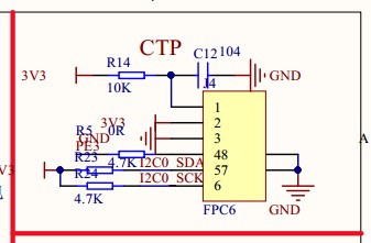
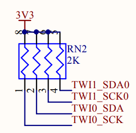
i2c0_pins: i2c0-pins {
pins = "PB6", "PB7";
function = "i2c0";
};
uart0_pb_pins: uart0-pb-pins {
pins = "PB8", "PB9";
function = "uart0";
};
mmc0_pins: mmc0-pins {
pins = "PF0", "PF1", "PF2", "PF3",
"PF4", "PF5";
function = "mmc0";
drive-strength = <30>;
bias-pull-up;
};
mmc1_pins: mmc1-pins {
pins = "PG0", "PG1", "PG2", "PG3",
"PG4", "PG5";
function = "mmc1";
drive-strength = <30>;
bias-pull-up;
};
spi0_pins: spi0-pins {
pins = "PC0", "PC1", "PC2", "PC3";
function = "spi0";
};
};
转自: https://whycan.cn/t_2360.html#p17976
https://whycan.cn/files/members/3/QQ20190421194526.jpg
在店主的耐心教导之下, 终于搞定 FT5336 电容触摸屏:
1. 店主建议修改电阻:
R15 --> 1.5K
R16 --> 1.5K
R29 --> 3.3K我实际修改:
R15 --> 1.2K
R16 --> 1.2K
R29 --> 3.7K2. 断开 R23 电阻, R21与R23的交叉点飞线到核心板的 PWM0(PB4), 这样FT5336的中断脚就是 EINT4, 复位脚是 PE23.
3. dts 修改:
&i2c0 {
status = "okay";ft6x06@38 {
compatible = "focaltech,ft6236";
reg = <0x38>;
interrupt-parent = <&pio>;
interrupts = <1 4 IRQ_TYPE_EDGE_FALLING>;
reset-gpios = <&pio 4 23 GPIO_ACTIVE_LOW>;
touchscreen-size-x = <480>;
touchscreen-size-y = <854>;
touchscreen-inverted-x;
touchscreen-swapped-x-y;
};};
4. 驱动添加:
CONFIG_TOUCHSCREEN_EDT_FT5X06=y
5. Linux 启动 log 信息:
[ 1.161482] i2c /dev entries driver
[ 1.494509] input: EP0110M09 as /devices/platform/soc/1c2ac00.i2c/i2c-0/0-0038/input/input1
晕哥 麻烦你把这个你配置的 interrupt-parent = <&pio>;贴出来我对比下 ,
我以前配置和也是和你一样的 ,我以前一直申请不了中断是不是和那几个电阻有关系了
在店主的耐心教导之下, 终于搞定 FT5336 电容触摸屏:
1. 店主建议修改电阻:
R15 --> 1.5K
R16 --> 1.5K
R29 --> 3.3K
我实际修改:
R15 --> 1.2K
R16 --> 1.2K
R29 --> 3.7K
2. 断开 R23 电阻, R21与R23的交叉点飞线到核心板的 PWM0(PB4), 这样FT5336的中断脚就是 EINT4, 复位脚是 PE23.
3. dts 修改:
&i2c0 {
status = "okay";ft6x06@38 {
compatible = "focaltech,ft6236";
reg = <0x38>;
interrupt-parent = <&pio>;
interrupts = <1 4 IRQ_TYPE_EDGE_FALLING>;
reset-gpios = <&pio 4 23 GPIO_ACTIVE_LOW>;
touchscreen-size-x = <480>;
touchscreen-size-y = <854>;
touchscreen-inverted-x;
touchscreen-swapped-x-y;
};};
4. 驱动添加:
CONFIG_TOUCHSCREEN_EDT_FT5X06=y
5. Linux 启动 log 信息:
[ 1.161482] i2c /dev entries driver
[ 1.494509] input: EP0110M09 as /devices/platform/soc/1c2ac00.i2c/i2c-0/0-0038/input/input1
大神最终咋整的?有详细点的思路不.....
哈哈 我当时主要是ft触摸芯片一直挂不上中断,你配置就按照我上面的配置为文件 ,
然后在代码中直接加入申请中断 后面就这样跑起来了 ,哈哈 一直都纳闷 为什么在配置文件中直接定义了中断管脚不可以, 还有什么不懂的可以加我QQ 1003676315