楼主 # 2022-01-22 16:28:15 分享评论
[记录]使用SPI驱动WS2811
市面上常见的2款串行可编程控制LED方案,分别是WS2811和WS2812。
其中,
[1]WS2811是芯片,常规供电为12V,按理说,驱动距离会远一些。
[2]WS2812是灯珠,把可编程芯片内嵌在灯珠里面,常规供电5V,按理说,驱动距离相对短。
相信很多朋友都在51单片机上面驱动过这个芯片,使用方法是:IO模拟单总线时序,达到传输RGB数据的效果。
因为WS2811/2812驱动时序,是us级的,IO模拟的方法,过度依赖CPU,这种做法实在不合理。
正确做法应该是借助片上的通讯外设,如UART/SPI等,兼容WS2811/2812的时序,腾出CPU资源,并且提高灯带驱动的稳定性。
本文章阐述,使用SPI驱动WS2811的思路。
先看手册:


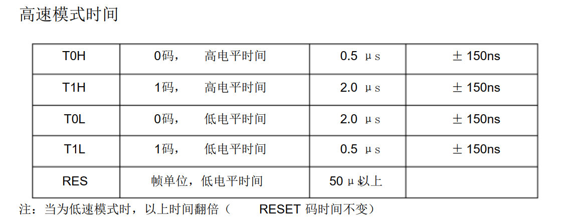
从WS2811的手册,可以得知( 高速模式下 ):
[1]这款芯片支持2种驱动速度:分别为高速模式和低速模式。
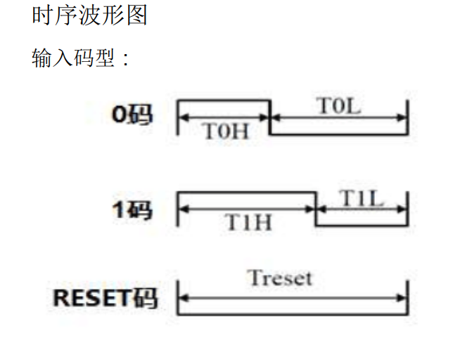
[2]对单总线送'0'码和'1'码,需要使用T0H / T1H / T0L /T1L搭配。
[3]搭配出来的'0'码和'1'码所占用时长皆为 2.5us。
[4]T0H = T1L = 0.5us
[5]T1H = T0L =2.0us = 4 * T0H = 4 * T1L
因此,SPI总线的驱动时钟,一个时钟脉冲的周期不能大于 T0H / T1L ,也就是不能大于0.5us。
我们试着就让SPI总线一个时钟脉冲的周期就等于0.5us,Tspiclk = 0.5us。
那么,频率Fspiclk = 1 / Tspiclk = 2MHz。
这种情况下,如果想要送RGB888数据中的 1 位 数据 到WS2811,SPI总线需要发出5个位的数据:
○  1 : 00001

○  0 : 11110
如果要发1字节数据(8个位),如R = 0xF0,对应二进制为:
1111 0000那么SPI应该发出这样的数据:
00001 00001 00001 00001 11110 11110 11110 11110对其进行组合,可以得到5个字节:
0000 1000 0100 0010 0001 1111 0111 1011 1101 1110所以,SPI应该发送的数据为:
0X08 0X42 0X1F 0X7B 0XDE同理,对于R 、G、 B都可以这样操作。
那么,也就是说,想要给一颗WS2811输送RGB888数据,需要发送5*3 = 15个字节。
最近编辑记录 LinjieGuo (2022-01-22 16:30:37)
离线
楼主 #1 2022-03-07 14:13:06 分享评论
Re: [记录]使用SPI驱动WS2811
时隔多日,回来续帖。
前面知道了原理,接下来,我们得生成一个color表。
color表的结构应该是这样:
uint8_t ws2811_color[256][5]={......} 其中,256对应一中颜色分量的颜色深浅,因为RGB各占8bit。
以下是我针对1楼的时序,生成的color表:
color_map_ws2811.c
color_map_ws2811.txt
下一步是借助color_map_ws2811.c文件,编写CH579M的驱动代码!
最近编辑记录 LinjieGuo (2022-03-07 14:15:59)
离线
#2 2022-03-09 23:16:09 分享评论
- xboot
- 会员
- 注册时间: 2019-10-15
- 已发帖子: 715
- 积分: 448
Re: [记录]使用SPI驱动WS2811
离线
楼主 #3 2022-03-10 08:39:29 分享评论
Re: [记录]使用SPI驱动WS2811
哈哈,大哥果然神速。
我昨天调试了半天ws2811。
怎么搞都不行,后面才发现。12V没接......
离线
楼主 #4 2022-03-10 09:02:39 分享评论
Re: [记录]使用SPI驱动WS2811
另外,可以把dma怼上去。
我是这样搞:
#define CHIP_NUM  100
typedef strut{
  uint8_t rst[200];    //0.5us *200 = 100us
  uint8_t frame[ CHIP_NUM ][3][5];
  //3 代表颜色分量,R / G / B
  //5 颜色数据,5字节SPI数据描述一个分量的颜色深浅
}ws28xx_t,ws28xx_pt;
然后定时使用DMA将帧内存通过SPI发送出去就可以了。
最近编辑记录 LinjieGuo (2022-03-10 09:04:32)
离线
#5 2022-03-10 09:06:17 分享评论
- xboot
- 会员
- 注册时间: 2019-10-15
- 已发帖子: 715
- 积分: 448
Re: [记录]使用SPI驱动WS2811
WS2812,WS2812B这两灯珠之间有啥区别,看TB卖的基本都是带B的。
离线
#6 2022-03-10 09:09:58 分享评论
- xboot
- 会员
- 注册时间: 2019-10-15
- 已发帖子: 715
- 积分: 448
Re: [记录]使用SPI驱动WS2811

搜了一个总结,用2M做SPI CLK,这个能算通用时序吗?
离线
#7 2022-03-10 09:20:59 分享评论
- xboot
- 会员
- 注册时间: 2019-10-15
- 已发帖子: 715
- 积分: 448
Re: [记录]使用SPI驱动WS2811
按这个总结的表格,最优的兼容性最好的,应该是T0H = 0.25us,T1H = 1us,T0L = 1us,T1L = 0.25us,两者间4倍关系,也就是说,上面的5bit表格无需改变,仅需将SPI的clk由原先的2M,换乘4M,就可以更通用了,当然这仅仅是分析,没有实际测试过。
离线
楼主 #8 2022-03-10 09:25:55 分享评论
Re: [记录]使用SPI驱动WS2811
对于上面我使用的WS2811的情况,2M SPI CLK,
情况如下:
(1)T0H = T1L = 0.5us = 500ns
(2)T1H = T0L =2.0us = 4 * T0H = 4 * T1L
看了你的WS2812手册里面给了个范围,
我们以WS2812B为准,将SPI CLK提升到4M。
那么,周期变成一半。
(1)T0H = T1L = 0.25us = 250ns
(2)T1H = T0L =1.0us = 1000ns =4 * T0H = 4 * T1L
观察了一下,完全符合WS2812B的时序要求。
(WS2812的数据传输速度是800KHz,WS2811(400KHz)的2倍)
所以,你至少使用4M的SPI CLK,才能驱动WS2812。
最近编辑记录 LinjieGuo (2022-03-10 09:26:48)
离线
楼主 #9 2022-03-10 09:47:48 分享评论
#10 2022-03-10 10:07:47 分享评论
- xboot
- 会员
- 注册时间: 2019-10-15
- 已发帖子: 715
- 积分: 448
Re: [记录]使用SPI驱动WS2811
是的,有这个可能,更长时间的复位,可以提升传输可靠性。
离线
#11 2022-03-10 20:22:11 分享评论
- xboot
- 会员
- 注册时间: 2019-10-15
- 已发帖子: 715
- 积分: 448
Re: [记录]使用SPI驱动WS2811
更新了下WS2812的驱动,添加缓存支持,提升刷新效率。
26a11c1820cdb4e202a99876c37971684c4634e5
 src/driver/led/ledstrip-ws2812.c | 37 ++++++++++++++++++++-----------------
 1 file changed, 20 insertions(+), 17 deletions(-)

diff --git a/src/driver/led/ledstrip-ws2812.c b/src/driver/led/ledstrip-ws2812.c
index 6f598bb3e..bc0736ef4 100644
--- a/src/driver/led/ledstrip-ws2812.c
+++ b/src/driver/led/ledstrip-ws2812.c
@@ -47,9 +47,11 @@ struct ledstrip_ws2812_pdata_t {
 	struct spi_device_t * spidev;
 	int count;
 	struct color_t * color;
+	int buflen;
+	unsigned char * buffer;
 };

-static const unsigned char ws2812_table[256][5]={
+static const unsigned char ws2812_map[256][5]={
 	{ 0x84, 0x21, 0x08, 0x42, 0x10, },
 	{ 0x84, 0x21, 0x08, 0x42, 0x1e, },
 	{ 0x84, 0x21, 0x08, 0x43, 0xd0, },
@@ -308,12 +310,6 @@ static const unsigned char ws2812_table[256][5]={
 	{ 0xf7, 0xbd, 0xef, 0x7b, 0xde, },
 };

-static void ledstrip_ws2812_send(struct ledstrip_t * strip, unsigned char byte)
-{
-	struct ledstrip_ws2812_pdata_t * pdat = (struct ledstrip_ws2812_pdata_t *)strip->priv;
-	spi_device_write_then_read(pdat->spidev, (void *)&ws2812_table[byte][0], 5, NULL, 0);
-}
-
 static void ledstrip_ws2812_set_count(struct ledstrip_t * strip, int n)
 {
 	struct ledstrip_ws2812_pdata_t * pdat = (struct ledstrip_ws2812_pdata_t *)strip->priv;
@@ -322,9 +318,20 @@ static void ledstrip_ws2812_set_count(struct ledstrip_t * strip, int n)
 	{
 		if(pdat->color)
 			free(pdat->color);
+		if(pdat->buffer)
+			free(pdat->buffer);
 		pdat->count = n;
 		pdat->color = malloc(pdat->count * sizeof(struct color_t));
 		memset(pdat->color, 0, pdat->count * sizeof(struct color_t));
+		pdat->buflen = n * 3 * 5 + 150;
+		pdat->buffer = malloc(pdat->buflen);
+		for(int i = 0; i < n; i++)
+		{
+			memcpy(&pdat->buffer[(i * 3 + 0) * 5], (void *)&ws2812_map[0][0], 5);
+			memcpy(&pdat->buffer[(i * 3 + 1) * 5], (void *)&ws2812_map[0][0], 5);
+			memcpy(&pdat->buffer[(i * 3 + 2) * 5], (void *)&ws2812_map[0][0], 5);
+		}
+		memset(&pdat->buffer[n * 3 * 5], 0, 150);
 	}
 }

@@ -338,6 +345,9 @@ static void ledstrip_ws2812_set_color(struct ledstrip_t * strip, int i, struct c
 {
 	struct ledstrip_ws2812_pdata_t * pdat = (struct ledstrip_ws2812_pdata_t *)strip->priv;
 	memcpy(&pdat->color[i], c, sizeof(struct color_t));
+	memcpy(&pdat->buffer[(i * 3 + 0) * 5], (void *)&ws2812_map[pdat->color[i].g][0], 5);
+	memcpy(&pdat->buffer[(i * 3 + 1) * 5], (void *)&ws2812_map[pdat->color[i].r][0], 5);
+	memcpy(&pdat->buffer[(i * 3 + 2) * 5], (void *)&ws2812_map[pdat->color[i].b][0], 5);
 }

 static void ledstrip_ws2812_get_color(struct ledstrip_t * strip, int i, struct color_t * c)
@@ -349,16 +359,7 @@ static void ledstrip_ws2812_get_color(struct ledstrip_t * strip, int i, struct c
 static void ledstrip_ws2812_refresh(struct ledstrip_t * strip)
 {
 	struct ledstrip_ws2812_pdata_t * pdat = (struct ledstrip_ws2812_pdata_t *)strip->priv;
-	int i;
-
-	for(i = 0; i < 150; i++)
-		ledstrip_ws2812_send(strip, 0x00);
-	for(i = 0; i < pdat->count; i++)
-	{
-		ledstrip_ws2812_send(strip, pdat->color[i].g);
-		ledstrip_ws2812_send(strip, pdat->color[i].r);
-		ledstrip_ws2812_send(strip, pdat->color[i].b);
-	}
+	spi_device_write_then_read(pdat->spidev, pdat->buffer, pdat->buflen, NULL, 0);
 }

 static struct device_t * ledstrip_ws2812_probe(struct driver_t * drv, struct dtnode_t * n)
@@ -386,6 +387,8 @@ static struct device_t * ledstrip_ws2812_probe(struct driver_t * drv, struct dtn
 	pdat->spidev = spidev;
 	pdat->count = 0;
 	pdat->color = NULL;
+	pdat->buflen = 0;
+	pdat->buffer = NULL;

 	strip->name = alloc_device_name(dt_read_name(n), dt_read_id(n));
 	strip->set_count = ledstrip_ws2812_set_count;
离线
#12 2022-03-12 08:33:34 分享评论
- xboot
- 会员
- 注册时间: 2019-10-15
- 已发帖子: 715
- 积分: 448
Re: [记录]使用SPI驱动WS2811
使用5bit,测试下来,发现可靠性偏低,感觉有必要搞成8bit,或者16bit,反正SPI时钟速度不是瓶颈。还有感觉想要搞通用时序,估计可靠性都好不到哪里去,最优的方式,还是用可配置的8bit或者16bit方案。
离线
楼主 #13 2022-03-12 09:52:01 分享评论
楼主 #14 2022-03-12 10:03:11 分享评论
#15 2022-03-12 10:20:05 分享评论
- xboot
- 会员
- 注册时间: 2019-10-15
- 已发帖子: 715
- 积分: 448
Re: [记录]使用SPI驱动WS2811
我看有的工程才有6.4M频率,8bit模式,1.25us / 8 = 0.15625us,然后8比特是3比5和5比3的方式
离线
楼主 #16 2022-03-12 10:21:18 分享评论
Re: [记录]使用SPI驱动WS2811
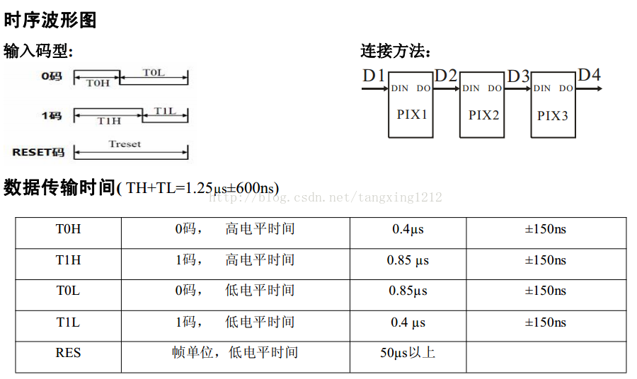
我从别的网站帖子上面看到了如下信息,我根据这些信息列出理论依据。
WS2812原理与实现
裁剪帖子的部分信息,可以看到,对于WS2812,其时序要求如下:
(1)T0H = T1L = 0.4us (±150ns,建立color表时,尽量不考虑误差范围,可作为芯片SPI时钟误差)
(2)T1H = T0L = 0.85us (±150ns,建立color表时,尽量不考虑误差范围,可作为芯片SPI时钟误差)
(3)与1楼的理论同理,得:
令SPI的一个时钟周期t = 0.05us,即SPI 的f = 20MHz。
T1H = T0L = 17个SPI数据
T0H = T1L = 8个SPI数据位
但是,芯片支持误差容忍(0.15us/150ns),
所以,可以尝试:
T1H = T0L = 16个SPI数据(少1个时钟节拍,0.05us/50ns)
T0H = T1L = 8个SPI数据位
最近编辑记录 LinjieGuo (2022-03-12 10:26:12)
离线
#17 2022-03-12 10:26:30 分享评论
- xboot
- 会员
- 注册时间: 2019-10-15
- 已发帖子: 715
- 积分: 448
Re: [记录]使用SPI驱动WS2811
按WS2812B规格书的完美参数
0.4 / 1.25 = 0.32
0.45 / 1.25 = 0.36
8bit模式
3 / 8 = 0.375
16bit模式
5 / 16 = 0.3125
6 / 16 = 0.375
看来16bit不是最优的,要找个介于0.32 和0.36之间的比值,会相对更好点。
比如12bit的话,感觉比例比较合适
4 / 12 = 0.333333333
当然12bit的话,频率就要变成9.6MHZ
离线
#18 2022-03-12 10:31:51 分享评论
- xboot
- 会员
- 注册时间: 2019-10-15
- 已发帖子: 715
- 积分: 448
Re: [记录]使用SPI驱动WS2811
综合判定下来,应该选择8bit模式,比较合理,资源也相对少一点,8bit的话,基本就可以不要表格了,直接运算就行了。
离线
楼主 #19 2022-03-12 11:22:15 分享评论
楼主 #20 2022-03-12 12:24:28 分享评论
Re: [记录]使用SPI驱动WS2811
大哥,ws2812你看看这个color表行不行。
SPI CLK 20MHz
T1H = T0L = 16个SPI数据 = 0.8us
T0H = T1L = 8个SPI数据位 = 0.4us
最近编辑记录 LinjieGuo (2022-03-12 12:26:45)
离线
太原小智科技有限责任公司 - 东莞哇酷科技有限公司联合开发