#1 全志 SOC » t113 fel阶段usb协议与启动后host模式不兼容 » 2025-02-27 17:16:58
- fxx
- 回复: 0
项目节省功耗,不设SD卡,但需要用一块t113芯片通过USB启动下一块t113芯片。
查阅t113芯片手册,只内置了ehci和ohci两个usb-controller。
插入虚拟机(主机)获得的log如下
[1019819.266687] usb 1-2.1: new full-speed USB device number 19 using uhci_hcd
[1019819.538587] usb 1-2.1: New USB device found, idVendor=1f3a, idProduct=efe8, bcdDevice= 2.b3
[1019819.538594] usb 1-2.1: New USB device strings: Mfr=0, Product=0, SerialNumber=0
BROM的fel启动系统在虚拟机(主机)显示用uhci识别,且禁用uhci后虚拟机(主机)无法识别此设备。推测t113的fel只支持uhci协议,而uhci与ohci和ehci都不兼容。
以下为t113片上系统部分log
# dmesg |grep hci
[    0.166027] Warning! fotg210_hcd should always be loaded before uhci_hcd and ohci_hcd, not after
[    1.244036] ehci-platform 4200000.usb: EHCI Host Controller
[    1.249662] ehci-platform 4200000.usb: new USB bus registered, assigned bus number 2
[    1.257663] ehci-platform 4200000.usb: irq 241, io mem 0x04200000
[    1.264949] ohci-platform 4200400.usb: Generic Platform OHCI controller
[    1.271605] ohci-platform 4200400.usb: new USB bus registered, assigned bus number 3
[    1.279541] ohci-platform 4200400.usb: irq 243, io mem 0x04200400
[    1.292862] ehci-platform 4200000.usb: USB 2.0 started, EHCI 1.00
[    1.319741] usb usb2: Manufacturer: Linux 6.1.0-rc3 ehci_hcd
[    1.378907] usb usb3: Manufacturer: Linux 6.1.0-rc3 ohci_hcd
[    2.238217] ehci-platform 4101000.usb: EHCI Host Controller
[    2.238217] ohci-platform 4101400.usb: Generic Platform OHCI controller
[    2.238261] ohci-platform 4101400.usb: new USB bus registered, assigned bus number 4
[    2.243836] ehci-platform 4101000.usb: new USB bus registered, assigned bus number 5
[    2.250573] ohci-platform 4101400.usb: irq 242, io mem 0x04101400
[    2.258274] ehci-platform 4101000.usb: irq 240, io mem 0x04101000
[    2.302824] ehci-platform 4101000.usb: USB 2.0 started, EHCI 1.00
[    2.329533] usb usb5: Manufacturer: Linux 6.1.0-rc3 ehci_hcd
[    2.370209] usb usb4: Manufacturer: Linux 6.1.0-rc3 ohci_hcd

//此时插入另一个未激活的t113设备
# [  499.222812] usb 3-1: new full-speed USB device number 2 using ohci-platform
[  499.487860] usb 3-1: New USB device found, idVendor=1f3a, idProduct=efe8, bcdDevice= 2.b3
[  499.496084] usb 3-1: New USB device strings: Mfr=0, Product=0, SerialNumber=0
[  512.702810] random: crng init done

# lsusb
Bus 005 Device 001: ID 1d6b:0002
Bus 003 Device 001: ID 1d6b:0001
Bus 001 Device 001: ID 1d6b:0002
Bus 004 Device 001: ID 1d6b:0001
Bus 002 Device 001: ID 1d6b:0002
Bus 003 Device 003: ID 1f3a:efe8
t113分配ohci来识别未激活的t113设备,却没有相应的驱动,搜了一下发现1f3a:efe8驱动都是windows系统上的,可否移植uhci的驱动给ohci使用?
以下摘录t113 user manual部分内容:
2.2.11.2 USB HOST
One USB 2.0 HOST (USB1), with integrated USB 2.0 analog PHY
Complies with USB2.0 Specification
Supports USB2.0 Host function - - - -
Compatible with Enhanced Host Controller Interface (EHCI) Specification, Version 1.0
Compatible with Open Host Controller Interface (OHCI) Specification, Version 1.0a
Supports High-Speed (HS, 480 Mbit/s), Full-Speed (FS, 12 Mbit/s) and Low-Speed (LS, 1.5 Mbit/s)
Device
Supports only 1 USB Root port shared between EHCI and OHCI
An internal DMA Controller for data transfer with memory2.2.11.1 USB DRD
One USB 2.0 DRD (USB0), with integrated USB 2.0 analog PHY
Complies with USB2.0 Specification
Supports USB Host function - - - -
Compatible with Enhanced Host Controller Interface (EHCI) Specification, Version 1.0
Compatible with Open Host Controller Interface (OHCI) Specification, Version 1.0a
Supports High-Speed (HS, 480 Mbit/s), Full-Speed (FS, 12 Mbit/s), and Low-Speed (LS, 1.5 Mbit/s)
Supports only 1 USB Root port shared between EHCI and OHCI
Supports USB Device function - - - - -
Supports High-Speed (HS, 480 Mbit/s), Full-Speed (FS, 12 Mbit/s)
Supports bi-directional endpoint0 (EP0) for Control transfer
Up to (8 KB + 64 Bytes) FIFO for all EPs (including EP0)
Up to 10 user-configurable endpoints (EP1+, EP1-, EP2+, EP2-, EP3+, EP3-, EP4+, EP4-, EP5+, EP5-) for
Bulk transfer, Isochronous transfer and Interrupt transfer
Supports interface to an external Normal DMA controller for every EP
Supports an internal DMA controller for data transfer with memory
Supports High-Bandwidth Isochronous & Interrupt transfers
Automated splitting/combining of packets for Bulk transfers
Supports point-to-point and point-to-multipoint transfer in both Host and Peripheral modes
Includes automatic ping capabilities
Soft connect/disconnect function
Performs all transaction scheduling in hardware
Power optimization and power management capabilities
Device and host controller share a 8K SRAM and a physical PHY
如何实现一块t113启动另一块t113芯片?请提供一切思路
#2 全志 SOC » awboot数据段和代码段存在0x10000偏移 » 2024-11-13 17:52:58
- fxx
- 回复: 0
背景:
使用t113s3芯片,LcTech开发板,此板可以脱离flash,直接从USB烧录bootloader、kernel等文件并直接启动(断电后清零);
使用awboot作为bootloader,经测试可以顺利进入main函数,可以从串口打出提示信息;
bootloader烧录在0x30000,并从0x30000开始启动(xfel write 0x30000 awboot-fel.bin ; xfel exec 0x30000);
问题简述:
阅读反汇编代码,发现逻辑完全符合要求,打印前后包含测试字符串地址的寄存器未变化及修改。
测试字符串的地址0x30050传给打印函数之前,打印发现确实为0x30050,(已给打印函数增加命令:打印之前先输出待打印字符串的地址)传给打印函数后打印地址变为0x20050,并概率触发读地址错误或打印无法显示的字符。给打印函数添加新命令,接到传入地址后,地址增加0x10000,结果全部正确。
后续启动过程也存在访问地址错误的问题,怀疑与字符串显示时的地址偏移有关,所以发帖咨询:rolleyes:
下附部分反汇编代码,及link.ld文件全文。
反汇编代码说明:
前半段说明了访问字符串地址的连续性,即寄存器r0储存的确实为实际字符串ASCII值7265777169757974,即"qwertyuio",且调用函数前后没有变化,后半段为输出函数,经测试可以正常使用。
awboot-fel.elf:     file format elf32-littlearm

Disassembly of section .text:

00038000 <__spl_start>:
   38000:	ea000016 	b	38060 <__spl_start+0x60>
   38004:	4e4f4765 	cdpmi	7, 4, cr4, cr15, cr5, {3}
   38008:	3054422e 	subscc	r4, r4, lr, lsr #4
   3800c:	12345678 	eorsne	r5, r4, #120, 12	; 0x7800000
   38010:	0000950c 	andeq	r9, r0, ip, lsl #10
   38014:	00000030 	andeq	r0, r0, r0, lsr r0
   38018:	30303033 	eorscc	r3, r0, r3, lsr r0
.............................
        char *str0 = "qwertyuio";
	send_string_via_usart((int)str0);
   38b3a:	486d      	ldr	r0, [pc, #436]	; (38cf0 <main+0x200>)
   38b3c:	f000 f92c 	bl	38d98 <send_string_via_usart>
.............................
   38cf0:	0003f88d 	andeq	pc, r3, sp, lsl #17
.............................
0003f88d <.rodata.main.str1.1>:

   3f88d:	72657771 	rsbvc	r7, r5, #29622272	; 0x1c40000
   3f891:	69757974 	ldmdbvs	r5!, {r2, r4, r5, r6, r8, fp, ip, sp, lr}^
.............................
void send_string_via_usart(int a) {
   38d98:	b570      	push	{r4, r5, r6, lr}

	int tmp = a+0x18000;
   38d9a:	f500 34c0 	add.w	r4, r0, #98304	; 0x18000
	char* str = (char*)tmp;
	putint((int)str);
	for(int i = 0;i<100;i++){
		if(str[i] == '\0')break;
		sunxi_usart_putc(&USART_DBG,str[i]);
   38d9e:	4e07      	ldr	r6, [pc, #28]	; (38dbc <send_string_via_usart+0x24>)
	putint((int)str);
   38da0:	4620      	mov	r0, r4
   38da2:	f104 0564 	add.w	r5, r4, #100	; 0x64
   38da6:	f7ff ffcd 	bl	38d44 <putint>
		if(str[i] == '\0')break;
   38daa:	7821      	ldrb	r1, [r4, #0]
   38dac:	b129      	cbz	r1, 38dba <send_string_via_usart+0x22>
		sunxi_usart_putc(&USART_DBG,str[i]);
   38dae:	4630      	mov	r0, r6
	for(int i = 0;i<100;i++){
   38db0:	3401      	adds	r4, #1
		sunxi_usart_putc(&USART_DBG,str[i]);
   38db2:	f001 fadb 	bl	3a36c <sunxi_usart_putc>
	for(int i = 0;i<100;i++){
   38db6:	42ac      	cmp	r4, r5
   38db8:	d1f7      	bne.n	38daa <send_string_via_usart+0x12>
	}
}
   38dba:	bd70      	pop	{r4, r5, r6, pc}
   38dbc:	0003f588 	andeq	pc, r3, r8, lsl #11
.........................
0003a36c <sunxi_usart_putc>:
		//uint32_t usart_base = usart->base;
		uint32_t usart_base = 0x02501400;

    // 等待发送缓冲区准备好
    do {
        __asm__ volatile (
   3a36c:	4b06      	ldr	r3, [pc, #24]	; (3a388 <sunxi_usart_putc+0x1c>)
   3a36e:	6fda      	ldr	r2, [r3, #124]	; 0x7c
   3a370:	f012 0f02 	tst.w	r2, #2
            "ldr %[status], [%[base], #0x7C] \n"  // 读取状态寄存器 (偏移 0x7C)
            "tst %[status], #(1 << 1) \n"         // 检查第 1 位 (发送缓冲区是否空)
            : [status] "=r" (status)              // 输出
            : [base] "r" (usart_base)             // 输入
        );
    } while ((status & (1 << 1)) == 0);
   3a374:	0790      	lsls	r0, r2, #30
   3a376:	d5fa      	bpl.n	3a36e <sunxi_usart_putc+0x2>

    // 发送字符
    __asm__ volatile (
   3a378:	6019      	str	r1, [r3, #0]
        : [ch] "r" ((uint32_t)c), [base] "r" (usart_base)
    );

    // 等待发送完成
    do {
        __asm__ volatile (
   3a37a:	6fda      	ldr	r2, [r3, #124]	; 0x7c
   3a37c:	f012 0f01 	tst.w	r2, #1
            "ldr %[status], [%[base], #0x7C] \n"  // 读取状态寄存器 (偏移 0x7C)
            "tst %[status], #(1 << 0) \n"         // 检查第 0 位 (发送是否完成)
            : [status] "=r" (status)              // 输出
            : [base] "r" (usart_base)             // 输入
        );
    } while ((status & (1 << 0)) != 0);
   3a380:	07d2      	lsls	r2, r2, #31
   3a382:	d4fa      	bmi.n	3a37a <sunxi_usart_putc+0xe>
}
   3a384:	4770      	bx	lr
   3a386:	bf00      	nop
   3a388:	02501400 	subseq	r1, r0, #0, 8
/**
* \file
*
* \brief Linker script for T113-S3 internal SRAM
*
* based on: Linker script for running in internal FLASH on the SAMD21G17D
* Copyright (c) 2018 Microchip Technology Inc.
*
* \asf_license_start
*
* \page License
*
* SPDX-License-Identifier: Apache-2.0
*
* Licensed under the Apache License, Version 2.0 (the "License"); you may
* not use this file except in compliance with the License.
* You may obtain a copy of the Licence at
*
* http://www.apache.org/licenses/LICENSE-2.0
*
* Unless required by applicable law or agreed to in writing, software
* distributed under the License is distributed on an AS IS BASIS, WITHOUT
* WARRANTIES OR CONDITIONS OF ANY KIND, either express or implied.
* See the License for the specific language governing permissions and
* limitations under the License.
*
* \asf_license_stop
*
*/
/* This file gets parsed by the preprocessor */
OUTPUT_FORMAT("elf32-littlearm", "elf32-littlearm", "elf32-littlearm")
OUTPUT_ARCH(arm)
SEARCH_DIR(.)
/* Memory Spaces Definitions */
MEMORY
{
ram (rwx) : ORIGIN = __RAM_BASE, LENGTH = 96K /* A1 + DSP0 IRAM + DSP0 DRAM0. 128K on boot mode, 96K on FEL mode */
}
/* The stack size used by the application. NOTE: you need to adjust according to your application. */
STACK_SIZE = 0x1000; /* 4KB */
ENTRY(reset)
/* Section Definitions */
SECTIONS
{
.text :
{
. = ALIGN(4);
PROVIDE(__spl_start = .);
*(.text .text.*)
. = ALIGN(4);
} > ram
. = ALIGN(4);
.ARM.exidx : {
__exidx_start = .;
*(.ARM.exidx* .gnu.linkonce.armexidx.*)
__exidx_end = .;
} > ram
PROVIDE(__spl_end = .);
PROVIDE(__spl_size = __spl_end - __spl_start);
/* .bss section which is used for uninitialized data */
.bss (NOLOAD) :
{
. = ALIGN(4);
_sbss = . ;
*(.bss .bss.*)
*(COMMON)
. = ALIGN(4);
_ebss = . ;
} > ram
.stack (NOLOAD):
{
. = ALIGN(8);
/* SRV stack section */
__stack_srv_start = .;
. += STACK_SIZE;
__stack_srv_end = .;
} > ram
. = ALIGN(4);
_end = . ;
}#4 全志 SOC » v3s官方buildroot文件系统卡在start kernerl... » 2024-06-06 10:16:58
- fxx
- 回复: 2
设备:v3s;
启动方式:无TF卡,USB sunxi-fel启动。
用晕哥的一键启动 https://whycan.com/t_2449.html ,在ubuntu linux虚拟机启动。
因为项目要求定制部分功能,所以zImage和rootfs需要自己定制,我用linux-4.10-zero编译zImage,用buildroot-2019.08编译rootfs,但是进度卡在start kernel...
经测试,晕哥的zImage+buildroot可以正常启动进系统;但是晕哥zImage+我的buildroot会卡在start kernel。问题锁定在buildroot,编译时我采用/config自带的licheepi_zero_defconfig,个人操作仅仅是取消勾选附带的kernel和u-boot下载。
注意到我的rootfs体积为16M,但是晕哥的是9M。
请提示我可能是哪里出了问题=(=(,感谢大家。
附log:
U-Boot SPL 2019.04-00743-g7d99406 (Apr 26 2019 - 02:24:09 -0400)
DRAM: 64 MiB
Trying to boot from FEL

U-Boot 2019.04-00743-g7d99406 (Apr 26 2019 - 02:24:09 -0400) Allwinner Technology

CPU:   Allwinner V3s (SUN8I 1681)
Model: Lichee Pi Zero
DRAM:  64 MiB
MMC:   mmc@01c0f000: 0
Loading Environment from FAT... Card did not respond to voltage select!
In:    serial@01c28000
Out:   serial@01c28000
Err:   serial@01c28000
Net:   No ethernet found.
starting USB...
No working controllers found
Hit any key to stop autoboot:  0
(FEL boot)
## Executing script at 41900000
## Loading init Ramdisk from Legacy Image at 41a00000 ...
   Image Name:   Root Filesystem
   Image Type:   ARM Linux RAMDisk Image (gzip compressed)
   Data Size:    16967436 Bytes = 16.2 MiB
   Load Address: 00000000
   Entry Point:  00000000
   Verifying Checksum ... OK
## Flattened Device Tree blob at 41800000
   Booting using the fdt blob at 0x41800000
   Loading Ramdisk to 41dd1000, end 42dff70c ... OK
   Loading Device Tree to 41dcb000, end 41dd0e4f ... OK

Starting kernel ...#5 Re: 全志 SOC » 利用USB启动mango pi t113的问题 » 2024-01-29 20:53:24
@夜里的星星
https://whycan.com/t_2388.html
参考这个贴,把启动内核需要的文件用命令一起传输过去就行了,可能sunxi-fel只能在BROM时期使用,uboot起来就用不了了。佐证:内核起来之后再在上位机使用sunxi-fel命令会显示“Allwinner devices not found”,内核彻底接管了开发板。
#6 Re: 全志 SOC » 解决 V3s / F1C100s Linux 显示 starting kernel ... 就没有然后的问题 (earlyprintk) » 2023-12-22 11:45:54
#7 Re: 全志 SOC » 利用USB启动mango pi t113的问题 » 2023-12-11 22:23:05
现已解决,mangopi板上已成功用USB启动uboot并进入内核。
uboot部分:
1、在arch\arm\dts中寻找本芯片对应的dtsi文件,例如‘u-boot-master\arch\arm\dts\sunxi-d1s-t113-mangopi-mq-r.dtsi’,里面有‘serial3 = &uart3;’,然后在'arch\riscv\dts'的'sunxi-d1s-t113.dtsi'找到uart3对应PB6和PB7,把串口插在此处,运行sunxi-fel uboot ....bin即可识别到uboot开机界面。如果版本正确的话就可以顺利启动 uboot。
2、启动uboot后会发现很多网络错误,我们是用USB传输的,直接无视即可。
3、uboot界面顺利启动,下一步是参考 https://linux-sunxi.org/FEL/USBBoot 以及 https://whycan.com/t_2388.html ,得到结论,要想顺利启动linux内核,芯片(或者说sunxi-tools)需要提供uboot-with-spl.bin(进入uboot)、zimage、设备树dtb、脚本scr、和内核文件系统。
3.1、zimage需要寻找符合自己芯片的buildroot,本芯片所需的zimage在 https://codeload.github.com/mangopi-sbc/buildroot-mangopi-r/zip/refs/heads/master 下载的buildroot,按照readme提供的方式编译(约40min)就可以得到。
3.2、设备树也是本buildroot提供的。
3.3、脚本在晕哥的基础上修改,直接放到linux运行,把run.bat的命令复制出来即可(可以省5积分哈哈)主要改了文件名,地址没有改。地址依据在uboot的sunxi-common.h下,如果有用其他芯片的可以参考该头文件的规则进行修改,根据sunxi版本和ram大小略有不同。
3.4、内核文件系统也是从buildroot里拿的,找rootfs.cpio.gz.uImage。
4、环境变量有可能出错,解决方法参见 https://whycan.com/t_635.html ,也可以直接把这段咒语写进scr,需要先修改cmd,然后用工具生成scr。
kernel部分:
1、恭喜找齐五个正确的文件(这花去了我主要的时间),uboot报错的大部分的错误都是五个文件中某一个不正确导致的,尤其是rootfs.cpio.gz.uImage。
2、下一个困扰我很久的问题是串口显示start kernel ...但是没有下文,我注意到板上LED亮起,猜想内核已启动,猜想正确。原因是linux的console所用的串口和uboot的串口不同,需要修改。直接打开刚刚五个文件中准备传给kernel的dtb,把里面的uart对应的P??和P??,统统改为PB6和PB7就可以。dtb是二进制不能直接打开,找到对应的dts,修改后用dtc工具转化成新的dtb就可以。
至此进入内核linux系统,进行下一项任务(待续)
#8 全志 SOC » 利用USB启动mango pi t113的问题 » 2023-11-22 11:45:44
- fxx
- 回复: 5
背景:芯片是t113,开发板是mango pi,在windowPC上用虚拟机ubuntu,通过机箱USB连接开发板的OTG口。
目标:利用芯片的fel功能将uboot以及linux内核烧录进ram,实现不插卡、不用flash直接启动。
易错点:sunxi-tools已采用master分支,uboot在make时已选用此开发板对应的deconfig配置。
已经实现:虚拟机可以sunxi-fel version识别芯片,并可以实现sunxi-fel uboot u-boot-sunxi-with-spl.bin烧录(见附图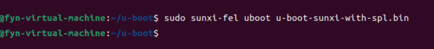 )
)
问题:烧录结束后没有任何反馈,连接串口到windows没有uboot的开机提示(正常用TF卡启动有欢迎界面),虚拟机命令行也没有欢迎语句,怀疑未正常烧录/启动。
辅助信息:烧录命令执行后,包括“sunxi-fel version”在内的所有代码均显示超时,进行新的测试只能按实体reset按钮。本机RAM大小128M。本机插卡可以正常使用。sunxi-fel splflash-info代码显示Invalid command splflash-info。
可能原因:uboot版本不对所以无法执行?但是uboot的deconfig关于mangopi只有一个;uboot已经运行但是没有显示?我需要在uboot添加什么代码才能有反馈,或者串口?
第一次发帖,格式不正确请见谅:rolleyes::rolleyes:
#9 Re: 全志 SOC » v3s CH340C » 2023-11-13 21:03:46
东莞哇酷科技有限公司开发