楼主 # 2022-08-24 21:48:07 分享评论
- qianniao29
- 会员
- 注册时间: 2020-05-19
- 已发帖子: 29
- 积分: 105.5
[v3x][kernel5.13.9]NT35510 LCD液晶屏(RGB+SPI接口)DRM驱动调试
之前做了个v3x小板,lcd调了挺长时间,分享下调试过程。
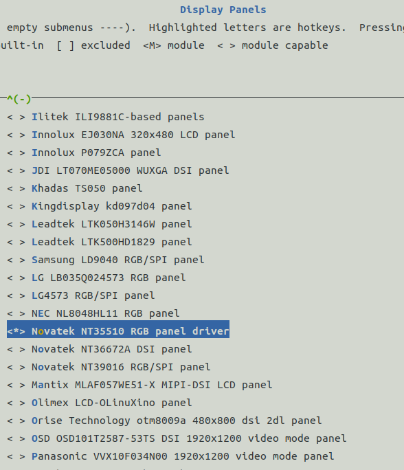
开启DRM,选择pannel中屏幕型号NT35510: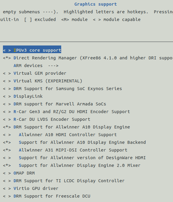
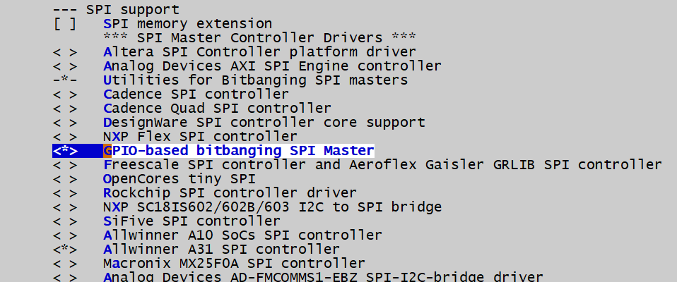
使用GPIO模拟spi,Linux有现成的驱动,开启即可。
在kernel 的menuconfig中选择driver/spi support/GPIO-based bitbanging SPI Master开启io模拟spi:
dts文件添加对应的节点:
spi_gpio {
        compatible = "spi-gpio";
        #address-cells = <0x1>;
        #size-cells = <0>;

        gpio-sck = <&pio 3 17 GPIO_ACTIVE_LOW>; //PD17
        gpio-miso = <&pio 3 15 GPIO_ACTIVE_LOW>; //PD15
        gpio-mosi = <&pio 3 14 GPIO_ACTIVE_LOW>; //PD14
        cs-gpios = <&pio 3 20 GPIO_ACTIVE_LOW>; //PD14
        num-chipselects = <1>;
        status = "okay";

        panel: display@0 {
            #address-cells = <1>;
            #size-cells = <0>;
            reg = <0>;
            compatible = "easyquick,lm040", "simple-panel";
            reset-gpios = <&pio 3 13 GPIO_ACTIVE_LOW>; //PD13
            pwren-gpios = <&pio 3 12 GPIO_ACTIVE_LOW>; //PD12
            spi-max-frequency = <2000000>;

            port@0 {
                reg = <0>;
                backlight = <&backlight>;
                #address-cells = <1>;
                #size-cells = <0>;

                panel_input: endpoint@0 {
                    reg = <0>;
                    remote-endpoint = <&tcon0_out_lcd>;
                };
            };
        };
    };
drivers/clk/sunxi-ng/ccu-sun8i-de2.c文件没有加入编译,需要修改drivers/clk/sunxi-ng/Makefile,添加
obj-$(CONFIG_DRM_SUN8I_MIXER) += ccu-sun8i-de2.o
模拟spi的时钟输出有bug,输出频率无法更改,需要修改spi-gpio.c中的延时函数:
diff --git a/drivers/spi/Kconfig b/drivers/spi/Kconfig
index 78f9fd0..0570dcd 100644
--- a/drivers/spi/Kconfig
+++ b/drivers/spi/Kconfig
@@ -143,6 +143,23 @@  config SPI_GPIO
       GPIO operations, you should be able to leverage that for better
       speed with a custom version of this driver; see the source code.

+config SLOWER_SPI_GPIO
+    bool "Enable delays in the GPIO-based bitbanging SPI Master"
+    default n
+    depends on SPI_GPIO
+    help
+      The GPIO bitbanging SPI master driver will run without any delays if this
+      option is not set. This option will enable the use of delays in the
+      operation of the GPIO bitbanging SPI master implementation to honour the
+      maximum speed of very slow devices.
+
+      To configure slow speed devices your board-specific setup logic must also
+      provide platform data assigning the speed for a device on a given chip
+      select of the GPIO bitbanging SPI master.
+
+      If your platform requires SPI buses driven at slow speeds select yes. If
+      in doubt, select no.
+
 config SPI_IMX_VER_IMX1
     def_bool y if SOC_IMX1

diff --git a/drivers/spi/spi_gpio.c b/drivers/spi/spi_gpio.c
index 63e51b0..b31fddd 100644
--- a/drivers/spi/spi_gpio.c
+++ b/drivers/spi/spi_gpio.c
@@ -19,6 +19,7 @@
  */
 #include <linux/kernel.h>
 #include <linux/init.h>
+#include <linux/delay.h>
 #include <linux/platform_device.h>
 #include <linux/gpio.h>

@@ -119,6 +120,9 @@  static inline int getmiso(const struct spi_device *spi)

 #undef pdata

+#if defined(CONFIG_SLOWER_SPI_GPIO)
+#define spidelay(nsecs) ndelay(nsecs)
+#else
 /*
  * NOTE:  this clocks "as fast as we can".  It "should" be a function of the
  * requested device clock.  Software overhead means we usually have trouble
@@ -126,6 +130,7 @@  static inline int getmiso(const struct spi_device *spi)
  * we'll just assume we never need additional per-bit slowdowns.
  */
 #define spidelay(nsecs)    do {} while (0)
+#endif

 #include "spi_bitbang_txrx.h"
参考NT35510 mipi接口的屏幕,修改为RGB接口驱动
drivers/gpu/drm/panel/panel-novatek-nt35510.c
// SPDX-License-Identifier: GPL-2.0-only
/*
 * Novatek NT35510 panel driver
 * Copyright (C) 2020 Linus Walleij <linus.walleij@linaro.org>
 * Based on code by Robert Teather (C) 2012 Samsung
 *
 * This display driver (and I refer to the physical component NT35510,
 * not this Linux kernel software driver) can handle:
 * 480x864, 480x854, 480x800, 480x720 and 480x640 pixel displays.
 * It has 480x840x24bit SRAM embedded for storing a frame.
 * When powered on the display is by default in 480x800 mode.
 *
 * The actual panels using this component have different names, but
 * the code needed to set up and configure the panel will be similar,
 * so they should all use the NT35510 driver with appropriate configuration
 * per-panel, e.g. for physical size.
 *
 * This driver is for the RGB (DPI) interface to panels using the NT35510.
 *
 */
#include <linux/backlight.h>
#include <linux/bitops.h>
#include <linux/gpio/consumer.h>
#include <linux/module.h>
#include <linux/of_device.h>
#include <linux/regmap.h>
#include <linux/regulator/consumer.h>

#include <linux/spi/spi.h>

#include <drm/drm_modes.h>
#include <drm/drm_panel.h>

#define MCS_CMD_MAUCCTR		0xF0 /* Manufacturer command enable */
#define MCS_CMD_READ_ID1	0xDA
#define MCS_CMD_READ_ID2	0xDB
#define MCS_CMD_READ_ID3	0xDC
#define MCS_CMD_MTP_READ_SETTING 0xF8 /* Uncertain about name */
#define MCS_CMD_MTP_READ_PARAM 0xFF /* Uncertain about name */
#define MCS_CMD_WRITE_BRIGHTNESS	0x51

/*
 * These manufacturer commands are available after we enable manufacturer
 * command set (MCS) for page 0.
 */
#define NT35510_P0_RGBCTR 0xB0
#define NT35510_P0_VIVIDCTR 0xB4
#define NT35510_P0_DOPCTR 0xB1
#define NT35510_P0_SDHDTCTR 0xB6
#define NT35510_P0_GSEQCTR 0xB7
#define NT35510_P0_SDEQCTR 0xB8
#define NT35510_P0_INVCTR 0xBC
#define NT35510_P0_DPFRCTR1 0xBD
#define NT35510_P0_DPFRCTR2 0xBE
#define NT35510_P0_DPFRCTR3 0xBF
#define NT35510_P0_DPMCTR12 0xCC

#define NT35510_P0_RGBCTR_LEN 5
#define NT35510_P0_DOPCTR_LEN 2
#define NT35510_P0_VIVIDCTR_LEN 1
#define NT35510_P0_GSEQCTR_LEN 2
#define NT35510_P0_SDEQCTR_LEN 4
#define NT35510_P0_SDVPCTR_LEN 1
#define NT35510_P0_DPFRCTR1_LEN 5
#define NT35510_P0_DPFRCTR2_LEN 5
#define NT35510_P0_DPFRCTR3_LEN 5
#define NT35510_P0_DPMCTR12_LEN 3

#define NT35510_DOPCTR_0_RAMKP BIT(7) /* Contents kept in sleep */
#define NT35510_DOPCTR_0_DSITE BIT(6) /* Enable TE signal */
#define NT35510_DOPCTR_0_DSIG BIT(5) /* Enable generic read/write */
#define NT35510_DOPCTR_0_DSIM BIT(4) /* Enable video mode on DSI */
#define NT35510_DOPCTR_0_EOTP BIT(3) /* Support EoTP */
#define NT35510_DOPCTR_0_N565 BIT(2) /* RGB or BGR pixel format */
#define NT35510_DOPCTR_1_TW_PWR_SEL BIT(4) /* TE power selector */
#define NT35510_DOPCTR_1_CRGB BIT(3) /* RGB or BGR byte order */
#define NT35510_DOPCTR_1_CTB BIT(2) /* Vertical scanning direction */
#define NT35510_DOPCTR_1_CRL BIT(1) /* Source driver data shift */
#define NT35510_P0_SDVPCTR_PRG BIT(2) /* 0 = normal operation, 1 = VGLO */
#define NT35510_P0_SDVPCTR_AVDD 0 /* source driver output = AVDD */
#define NT35510_P0_SDVPCTR_OFFCOL 1 /* source driver output = off color */
#define NT35510_P0_SDVPCTR_AVSS 2 /* source driver output = AVSS */
#define NT35510_P0_SDVPCTR_HI_Z 3 /* source driver output = High impedance */

/*
 * These manufacturer commands are available after we enable manufacturer
 * command set (MCS) for page 1.
 */
#define NT35510_P1_SETAVDD 0xB0
#define NT35510_P1_SETAVEE 0xB1
#define NT35510_P1_SETVCL 0xB2
#define NT35510_P1_SETVGH 0xB3
#define NT35510_P1_SETVRGH 0xB4
#define NT35510_P1_SETVGL 0xB5
#define NT35510_P1_BT1CTR 0xB6
#define NT35510_P1_BT2CTR 0xB7
#define NT35510_P1_BT3CTR 0xB8
#define NT35510_P1_BT4CTR 0xB9 /* VGH boosting times/freq */
#define NT35510_P1_BT5CTR 0xBA
#define NT35510_P1_PFMCTR 0xBB
#define NT35510_P1_SETVGP 0xBC
#define NT35510_P1_SETVGN 0xBD
#define NT35510_P1_SETVCMOFF 0xBE
#define NT35510_P1_VGHCTR 0xBF /* VGH output ctrl */
#define NT35510_P1_SET_GAMMA_RED_POS 0xD1
#define NT35510_P1_SET_GAMMA_GREEN_POS 0xD2
#define NT35510_P1_SET_GAMMA_BLUE_POS 0xD3
#define NT35510_P1_SET_GAMMA_RED_NEG 0xD4
#define NT35510_P1_SET_GAMMA_GREEN_NEG 0xD5
#define NT35510_P1_SET_GAMMA_BLUE_NEG 0xD6

/* AVDD and AVEE setting 3 bytes */
#define NT35510_P1_AVDD_LEN 3
#define NT35510_P1_AVEE_LEN 3
#define NT35510_P1_VGH_LEN 3
#define NT35510_P1_VGL_LEN 3
#define NT35510_P1_VGP_LEN 3
#define NT35510_P1_VGN_LEN 3
/* BT1CTR thru BT5CTR setting 3 bytes */
#define NT35510_P1_BT1CTR_LEN 3
#define NT35510_P1_BT2CTR_LEN 3
#define NT35510_P1_BT4CTR_LEN 3
#define NT35510_P1_BT5CTR_LEN 3
/* 52 gamma parameters times two per color: positive and negative */
#define NT35510_P1_GAMMA_LEN 52

/**
 * struct nt35510_config - the display-specific NT35510 configuration
 *
 * Some of the settings provide an array of bytes, A, B C which mean:
 * A = normal / idle off mode
 * B = idle on mode
 * C = partial / idle off mode
 *
 * Gamma correction arrays are 10bit numbers, two consecutive bytes
 * makes out one point on the gamma correction curve. The points are
 * not linearly placed along the X axis, we get points 0, 1, 3, 5
 * 7, 11, 15, 23, 31, 47, 63, 95, 127, 128, 160, 192, 208, 224, 232,
 * 240, 244, 248, 250, 252, 254, 255. The voltages tuples form
 * V0, V1, V3 ... V255, with 0x0000 being the lowest voltage and
 * 0x03FF being the highest voltage.
 *
 * Each value must be strictly higher than the previous value forming
 * a rising curve like this:
 *
 * ^
 * |                                        V255
 * |                                 V254
 * |                         ....
 * |                    V5
 * |           V3
 * |     V1
 * | V0
 * +------------------------------------------->
 *
 * The details about all settings can be found in the NT35510 Application
 * Note.
 */
struct nt35510_config {
	/**
	 * @width_mm: physical panel width [mm]
	 */
	u32 width_mm;
	/**
	 * @height_mm: physical panel height [mm]
	 */
	u32 height_mm;
	/**
	 * @mode: the display mode. This is only relevant outside the panel
	 * in video mode: in command mode this is configuring the internal
	 * timing in the display controller.
	 */
	const struct drm_display_mode mode;
	/**
	 * @avdd: setting for AVDD ranging from 0x00 = 6.5V to 0x14 = 4.5V
	 * in 0.1V steps the default is 0x05 which means 6.0V
	 */
	u8 avdd[NT35510_P1_AVDD_LEN];
	/**
	 * @bt1ctr: setting for boost power control for the AVDD step-up
	 * circuit (1)
	 * bits 0..2 in the lower nibble controls PCK, the booster clock
	 * frequency for the step-up circuit:
	 * 0 = Hsync/32
	 * 1 = Hsync/16
	 * 2 = Hsync/8
	 * 3 = Hsync/4
	 * 4 = Hsync/2
	 * 5 = Hsync
	 * 6 = Hsync x 2
	 * 7 = Hsync x 4
	 * bits 4..6 in the upper nibble controls BTP, the boosting
	 * amplification for the the step-up circuit:
	 * 0 = Disable
	 * 1 = 1.5 x VDDB
	 * 2 = 1.66 x VDDB
	 * 3 = 2 x VDDB
	 * 4 = 2.5 x VDDB
	 * 5 = 3 x VDDB
	 * The defaults are 4 and 4 yielding 0x44
	 */
	u8 bt1ctr[NT35510_P1_BT1CTR_LEN];
	/**
	 * @avee: setting for AVEE ranging from 0x00 = -6.5V to 0x14 = -4.5V
	 * in 0.1V steps the default is 0x05 which means -6.0V
	 */
	u8 avee[NT35510_P1_AVEE_LEN];
	/**
	 * @bt2ctr: setting for boost power control for the AVEE step-up
	 * circuit (2)
	 * bits 0..2 in the lower nibble controls NCK, the booster clock
	 * frequency, the values are the same as for PCK in @bt1ctr.
	 * bits 4..5 in the upper nibble controls BTN, the boosting
	 * amplification for the the step-up circuit.
	 * 0 = Disable
	 * 1 = -1.5 x VDDB
	 * 2 = -2 x VDDB
	 * 3 = -2.5 x VDDB
	 * 4 = -3 x VDDB
	 * The defaults are 4 and 3 yielding 0x34
	 */
	u8 bt2ctr[NT35510_P1_BT2CTR_LEN];
	/**
	 * @vgh: setting for VGH ranging from 0x00 = 7.0V to 0x0B = 18.0V
	 * in 1V steps, the default is 0x08 which means 15V
	 */
	u8 vgh[NT35510_P1_VGH_LEN];
	/**
	 * @bt4ctr: setting for boost power control for the VGH step-up
	 * circuit (4)
	 * bits 0..2 in the lower nibble controls HCK, the booster clock
	 * frequency, the values are the same as for PCK in @bt1ctr.
	 * bits 4..5 in the upper nibble controls BTH, the boosting
	 * amplification for the the step-up circuit.
	 * 0 = AVDD + VDDB
	 * 1 = AVDD - AVEE
	 * 2 = AVDD - AVEE + VDDB
	 * 3 = AVDD x 2 - AVEE
	 * The defaults are 4 and 3 yielding 0x34
	 */
	u8 bt4ctr[NT35510_P1_BT4CTR_LEN];
	/**
	 * @vgl: setting for VGL ranging from 0x00 = -2V to 0x0f = -15V in
	 * 1V steps, the default is 0x08 which means -10V
	 */
	u8 vgl[NT35510_P1_VGL_LEN];
	/**
	 * @bt5ctr: setting for boost power control for the VGL step-up
	 * circuit (5)
	 * bits 0..2 in the lower nibble controls LCK, the booster clock
	 * frequency, the values are the same as for PCK in @bt1ctr.
	 * bits 4..5 in the upper nibble controls BTL, the boosting
	 * amplification for the the step-up circuit.
	 * 0 = AVEE + VCL
	 * 1 = AVEE - AVDD
	 * 2 = AVEE + VCL - AVDD
	 * 3 = AVEE x 2 - AVDD
	 * The defaults are 3 and 2 yielding 0x32
	 */
	u8 bt5ctr[NT35510_P1_BT5CTR_LEN];
	/**
	 * @vgp: setting for VGP, the positive gamma divider voltages
	 * VGMP the high voltage and VGSP the low voltage.
	 * The first byte contains bit 8 of VGMP and VGSP in bits 4 and 0
	 * The second byte contains bit 0..7 of VGMP
	 * The third byte contains bit 0..7 of VGSP
	 * VGMP 0x00 = 3.0V .. 0x108 = 6.3V in steps of 12.5mV
	 * VGSP 0x00 = 0V .. 0x111 = 3.7V in steps of 12.5mV
	 */
	u8 vgp[NT35510_P1_VGP_LEN];
	/**
	 * @vgn: setting for VGN, the negative gamma divider voltages,
	 * same layout of bytes as @vgp.
	 */
	u8 vgn[NT35510_P1_VGN_LEN];
	/**
	 * @sdeqctr: Source driver control settings, first byte is
	 * 0 for mode 1 and 1 for mode 2. Mode 1 uses two steps and
	 * mode 2 uses three steps meaning EQS3 is not used in mode
	 * 1. Mode 2 is default. The last three parameters are EQS1, EQS2
	 * and EQS3, setting the rise time for each equalizer step:
	 * 0x00 = 0.0 us to 0x0f = 7.5 us in steps of 0.5us. The default
	 * is 0x07 = 3.5 us.
	 */
	u8 sdeqctr[NT35510_P0_SDEQCTR_LEN];
	/**
	 * @sdvpctr: power/voltage behaviour during vertical porch time
	 */
	u8 sdvpctr;
	/**
	 * @rgb_mode: the operation status and vertical / horizontal porch
	 * of RGB interface. The setting becomes effective as soon as the
	 * command is received.
	 */
	u8 rgb_mode;
	/**
	 * @psel: pixel clock divisor: 0 = 1, 1 = 2, 2 = 4, 3 = 8.
	 */
	u8 psel;
	/**
	 * @dpmctr12: Display timing control 12
	 * Byte 1 bit 4 selects LVGL voltage level: 0 = VGLX, 1 = VGL_REG
	 * Byte 1 bit 1 selects gate signal mode: 0 = non-overlap, 1 = overlap
	 * Byte 1 bit 0 selects output signal control R/L swap, 0 = normal
	 * 1 = swap all O->E, L->R
	 * Byte 2 is CLW delay clock for CK O/E and CKB O/E signals:
	 * 0x00 = 0us .. 0xFF = 12.75us in 0.05us steps
	 * Byte 3 is FTI_H0 delay time for STP O/E signals:
	 * 0x00 = 0us .. 0xFF = 12.75us in 0.05us steps
	 */
	u8 dpmctr12[NT35510_P0_DPMCTR12_LEN];
	/**
	 * @gamma_corr_pos_r: Red gamma correction parameters, positive
	 */
	u8 gamma_corr_pos_r[NT35510_P1_GAMMA_LEN];
	/**
	 * @gamma_corr_pos_g: Green gamma correction parameters, positive
	 */
	u8 gamma_corr_pos_g[NT35510_P1_GAMMA_LEN];
	/**
	 * @gamma_corr_pos_b: Blue gamma correction parameters, positive
	 */
	u8 gamma_corr_pos_b[NT35510_P1_GAMMA_LEN];
	/**
	 * @gamma_corr_neg_r: Red gamma correction parameters, negative
	 */
	u8 gamma_corr_neg_r[NT35510_P1_GAMMA_LEN];
	/**
	 * @gamma_corr_neg_g: Green gamma correction parameters, negative
	 */
	u8 gamma_corr_neg_g[NT35510_P1_GAMMA_LEN];
	/**
	 * @gamma_corr_neg_b: Blue gamma correction parameters, negative
	 */
	u8 gamma_corr_neg_b[NT35510_P1_GAMMA_LEN];
};

/**
 * struct nt35510 - state container for the NT35510 panel
 */
struct nt35510 {
	/**
	 * @dev: the container device
	 */
	struct device *dev;
	/**
	 * @conf: the specific panel configuration, as the NT35510
	 * can be combined with many physical panels, they can have
	 * different physical dimensions and gamma correction etc,
	 * so this is stored in the config.
	 */
	const struct nt35510_config *conf;
	/**
	 * @panel: the DRM panel object for the instance
	 */
	struct drm_panel panel;
	/**
	 * @regmap: the regmap for the SPI
	 */
	struct regmap *regmap;
	/**
	 * @supplies: regulators supplying the panel
	 */
	struct regulator_bulk_data supplies[2];
	/**
	 * @reset_gpio: the reset line
	 */
	struct gpio_desc *reset_gpio;
	 /**
	 * @pwren_gpio: the power enable line
	 */
	struct gpio_desc *pwren_gpio;

	u32 swap_rb;
};

/* Manufacturer command has strictly this byte sequence */
static const u8 nt35510_mauc_mtp_read_param[] = { 0xAA, 0x55, 0x25, 0x01 };
static const u8 nt35510_mauc_mtp_read_setting[] = { 0x01, 0x02, 0x00, 0x20,
						    0x33, 0x13, 0x00, 0x40,
						    0x00, 0x00, 0x23, 0x02 };
static const u8 nt35510_mauc_select_page_0[] = { 0x55, 0xAA, 0x52, 0x08, 0x00 };
static const u8 nt35510_mauc_select_page_1[] = { 0x55, 0xAA, 0x52, 0x08, 0x01 };
static const u8 nt35510_vgh_on[] = { 0x01 };

static inline struct nt35510 *panel_to_nt35510(struct drm_panel *panel)
{
	return container_of(panel, struct nt35510, panel);
}


#define NT35510_ROTATE_0_SETTING	0x02
#define NT35510_ROTATE_180_SETTING	0x00

static int nt35510_send(struct nt35510 *nt, u8 cmd, u8 len, const u8 *seq)
{
	struct spi_device *spi = to_spi_device(nt->dev);
	int	ret = 0;
	u8	buffer[2];
	u8	index = 0;

	if(len == 0)
	{
		buffer[0] = 0x20;	//cmd high byte
		buffer[1] = cmd;
		if((ret = spi_write_then_read(spi, buffer, 2, NULL, 0)) !=0)
			return ret;
		buffer[0] = 0x00;	//cmd low byte
		buffer[1] = 0x00;
		if((ret = spi_write_then_read(spi, buffer, 2, NULL, 0)) !=0)
			return ret;

	}
	while (index < len)
	{
		buffer[0] = 0x20;	//cmd high byte
		buffer[1] = cmd;
		if((ret = spi_write_then_read(spi, buffer, 2, NULL, 0)) !=0)
			break;
		buffer[0] = 0x00;	//cmd low byte
		buffer[1] = index;
		if((ret = spi_write_then_read(spi, buffer, 2, NULL, 0)) !=0)
			break;
		buffer[0] = 0x40;	//data low byte
		buffer[1] = seq[index];
		if((ret = spi_write_then_read(spi, buffer, 2, NULL, 0)) !=0)
			break;
		index++;
	}

	return ret;
}

static int nt35510_read(struct nt35510 *nt, u8 cmd, u8 len, const u8 *seq)
{
	struct spi_device *spi = to_spi_device(nt->dev);
	u8	buffer[2];
	u8	index = 0;
	int	ret = 0;

	while (index < len)
	{
		buffer[0] = 0x20;	//cmd high byte
		buffer[1] = cmd;
		if((ret = spi_write_then_read(spi, buffer, 2, NULL, 0)) !=0)
			break;

		buffer[0] = 0x00;	//cmd low byte
		buffer[1] = index;
		if((ret = spi_write_then_read(spi, buffer, 2, NULL, 0)) !=0)
			break;

		buffer[0] = 0xC0;	//data low byte
		if((ret = spi_write_then_read(spi, buffer, 1, (void*)&seq[index], 1)) !=0)
			break;
		index++;
	}

	return ret;
}


static int nt35510_read_id(struct nt35510 *nt)
{
	u8 id1, id2, id3;
	int ret;

	ret = nt35510_read(nt, MCS_CMD_READ_ID1, 1, &id1);
	if (ret < 0) {
		dev_err(nt->dev, "could not read MTP ID1\n");
		return ret;
	}
	ret = nt35510_read(nt, MCS_CMD_READ_ID2, 1, &id2);
	if (ret < 0) {
		dev_err(nt->dev, "could not read MTP ID2\n");
		return ret;
	}
	ret = nt35510_read(nt, MCS_CMD_READ_ID3, 1, &id3);
	if (ret < 0) {
		dev_err(nt->dev, "could not read MTP ID3\n");
		return ret;
	}

	/*
	 * Multi-Time Programmable (?) memory contains manufacturer
	 * ID (e.g. Hydis 0x55), driver ID (e.g. NT35510 0xc0) and
	 * version.
	 */
	dev_info(nt->dev, "MTP ID manufacturer: %02x version: %02x driver: %02x\n", id1, id2, id3);
	ret = nt35510_read(nt, 0x0c, 1, &id1);
	dev_info(nt->dev, "Pixel Format:0x%x\n", id1);

	return 0;
}

/**
 * nt35510_setup_power() - set up power config in page 1
 * @nt: the display instance to set up
 */
static int nt35510_setup_power(struct nt35510 *nt)
{
	int ret;

	ret = nt35510_send(nt,  NT35510_P1_SETAVDD,
				NT35510_P1_AVDD_LEN,
				nt->conf->avdd);
	if (ret)
		return ret;
	ret = nt35510_send(nt,  NT35510_P1_BT1CTR,
				NT35510_P1_BT1CTR_LEN,
				nt->conf->bt1ctr);
	if (ret)
		return ret;
	ret = nt35510_send(nt,  NT35510_P1_SETAVEE,
				NT35510_P1_AVEE_LEN,
				nt->conf->avee);
	if (ret)
		return ret;
	ret = nt35510_send(nt,  NT35510_P1_BT2CTR,
				NT35510_P1_BT2CTR_LEN,
				nt->conf->bt2ctr);
	if (ret)
		return ret;
	ret = nt35510_send(nt,  NT35510_P1_SETVGH,
				NT35510_P1_VGH_LEN,
				nt->conf->vgh);
	if (ret)
		return ret;
	ret = nt35510_send(nt,  NT35510_P1_BT4CTR,
				NT35510_P1_BT4CTR_LEN,
				nt->conf->bt4ctr);
	if (ret)
		return ret;
	ret = nt35510_send(nt,  NT35510_P1_VGHCTR,
				ARRAY_SIZE(nt35510_vgh_on),
				nt35510_vgh_on);
	if (ret)
		return ret;
	ret = nt35510_send(nt,  NT35510_P1_SETVGL,
				NT35510_P1_VGL_LEN,
				nt->conf->vgl);
	if (ret)
		return ret;
	ret = nt35510_send(nt,  NT35510_P1_BT5CTR,
				NT35510_P1_BT5CTR_LEN,
				nt->conf->bt5ctr);
	if (ret)
		return ret;
	ret = nt35510_send(nt,  NT35510_P1_SETVGP,
				NT35510_P1_VGP_LEN,
				nt->conf->vgp);
	if (ret)
		return ret;
	ret = nt35510_send(nt,  NT35510_P1_SETVGN,
				NT35510_P1_VGN_LEN,
				nt->conf->vgn);
	if (ret)
		return ret;

	/* Typically 10 ms */
	usleep_range(10000, 20000);

	return 0;
}

/**
 * nt35510_setup_display() - set up display config in page 0
 * @nt: the display instance to set up
 */
static int nt35510_setup_display(struct nt35510 *nt)
{
	const struct nt35510_config *conf = nt->conf;
	u8 dopctr[NT35510_P0_DOPCTR_LEN];
	u8 gseqctr[NT35510_P0_GSEQCTR_LEN];
	u8 dpfrctr[NT35510_P0_DPFRCTR1_LEN];
	/* FIXME: set up any rotation (assume none for now) */
	u8 val;
	int ret;

	/* Enable TE, EoTP and RGB pixel format */
	dopctr[0] = 0x10;
	ret = nt35510_send(nt,  NT35510_P0_VIVIDCTR,
				NT35510_P0_VIVIDCTR_LEN,
				dopctr);
	if (ret)
		return ret;

/*	ret = mipi_dsi_dcs_write(dsi, MIPI_DCS_SET_ADDRESS_MODE, &addr_mode,
				 sizeof(addr_mode));
	if (ret < 0)
		return ret;*/

	/*
	 * Source data hold time, default 0x05 = 2.5us
	 * 0x00..0x3F = 0 .. 31.5us in steps of 0.5us
	 * 0x0A = 5us
	 */
	val = 0x0A;
	ret = nt35510_send(nt, NT35510_P0_SDHDTCTR, sizeof(val),
				&val);
	if (ret < 0)
		return ret;

	/* EQ control for gate signals, 0x00 = 0 us */
	gseqctr[0] = 0x00;
	gseqctr[1] = 0x00;
	ret = nt35510_send(nt,  NT35510_P0_GSEQCTR,
				NT35510_P0_GSEQCTR_LEN,
				gseqctr);
	if (ret)
		return ret;

	ret = nt35510_send(nt,  NT35510_P0_SDEQCTR,
				NT35510_P0_SDEQCTR_LEN,
				conf->sdeqctr);
	if (ret)
		return ret;

	dpfrctr[0] = 0x05;
	dpfrctr[1] = 0x05;
	dpfrctr[2] = 0x05;
	ret = nt35510_send(nt, NT35510_P0_INVCTR,
				3, dpfrctr);
	if (ret < 0)
		return ret;

	/*
	 * Display timing control for active and idle off mode:
	 * the first byte contains
	 * the two high bits of T1A and second byte the low 8 bits, and
	 * the valid range is 0x100 (257) to 0x3ff (1023) representing
	 * 258..1024 (+1) pixel clock ticks for one scanline. At 20MHz pixel
	 * clock this covers the range of 12.90us .. 51.20us in steps of
	 * 0.05us, the default is 0x184 (388) representing 389 ticks.
	 * The third byte is VBPDA, vertical back porch display active
	 * and the fourth VFPDA, vertical front porch display active,
	 * both given in number of scanlines in the range 0x02..0xff
	 * for 2..255 scanlines. The fifth byte is 2 bits selecting
	 * PSEL for active and idle off mode, how much the 20MHz clock
	 * is divided by 0..3.  This needs to be adjusted to get the right
	 * frame rate.
	 */
	dpfrctr[0] = conf->rgb_mode;
	/* V-Sync back porch */
	dpfrctr[1] = conf->mode.vtotal - conf->mode.vsync_start;
	/* V-Sync front porch */
	dpfrctr[2] = conf->mode.vsync_start - conf->mode.vdisplay;
	/* V-Sync back porch */
	dpfrctr[3] = conf->mode.htotal - conf->mode.hsync_start;
	/* front porch */
	dpfrctr[4] = conf->mode.hsync_start - conf->mode.hdisplay;
	ret = nt35510_send(nt,  NT35510_P0_RGBCTR,
				NT35510_P0_RGBCTR_LEN,
				dpfrctr);
	if (ret)
		return ret;

	if(nt->swap_rb)
	{
		dopctr[0] = 0x08; //swap R and B
		ret = nt35510_send(nt, 0x36, 1, dopctr);
		dopctr[0] = 0x0;
		ret = nt35510_read(nt, 0x0b, 1, dopctr);
			dev_info(nt->dev, "RGB Format:0x%x\n", dopctr[0]);
	}

	ret = nt35510_send(nt, 0x11, 0, NULL); //sleep out & booster on
	usleep_range(120000, 140000);
	ret = nt35510_send(nt, 0x29, 0, NULL); //Display On
	usleep_range(120000, 140000);
#if 0
//	ret = nt35510_send(nt, 0x23, 1, dopctr); //All pixel on
	dpfrctr[0] = 0;
	dpfrctr[1] = 0;
	dpfrctr[2] = 0x01;
	dpfrctr[3] = 0x90;
	ret = nt35510_send(nt, 0x2a, 4, dpfrctr);
	ret = nt35510_send(nt, 0x2b, 4, dpfrctr);
	ret = nt35510_send(nt, 0x2c, 0, NULL);

	dopctr[0] = 0;
	ret = nt35510_send(nt, 0x4a, 1, dpfrctr);
#endif

	return 0;
}

static int nt35510_set_brightness(struct backlight_device *bl)
{
	struct nt35510 *nt = bl_get_data(bl);
	u8 brightness = bl->props.brightness;
	int ret;

	dev_dbg(nt->dev, "set brightness %d\n", brightness);
	ret = nt35510_send(nt, MCS_CMD_WRITE_BRIGHTNESS,
				1, &brightness);
	if (ret < 0)
		return ret;

	return 0;
}

static const struct backlight_ops nt35510_bl_ops = {
	.update_status = nt35510_set_brightness,
};

/*
 * This power-on sequence
 */
static int nt35510_power_on(struct nt35510 *nt)
{
	int ret;

	ret = regulator_bulk_enable(ARRAY_SIZE(nt->supplies), nt->supplies);
	if (ret < 0) {
		dev_err(nt->dev, "unable to enable regulators\n");
		return ret;
	}

	/* Toggle RESET in accordance with datasheet page 370 */
	if (nt->reset_gpio) {
		gpiod_set_value(nt->reset_gpio, 1);
		/* Active min 10 us according to datasheet, let's say 20 */
		usleep_range(120000, 140000);
		gpiod_set_value(nt->reset_gpio, 0);
		/*
		 * 5 ms during sleep mode, 120 ms during sleep out mode
		 * according to datasheet, let's use 120-140 ms.
		 */
		usleep_range(120000, 140000);
	}

	ret = nt35510_send(nt,  MCS_CMD_MTP_READ_PARAM,
				ARRAY_SIZE(nt35510_mauc_mtp_read_param),
				nt35510_mauc_mtp_read_param);
	if (ret)
		return ret;

	ret = nt35510_send(nt,  MCS_CMD_MTP_READ_SETTING,
				ARRAY_SIZE(nt35510_mauc_mtp_read_setting),
				nt35510_mauc_mtp_read_setting);
	if (ret)
		return ret;

	nt35510_read_id(nt);

	/* Set up stuff in  manufacturer control, page 1 */
	ret = nt35510_send(nt,  MCS_CMD_MAUCCTR,
				ARRAY_SIZE(nt35510_mauc_select_page_1),
				nt35510_mauc_select_page_1);
	if (ret)
		return ret;

	ret = nt35510_setup_power(nt);
	if (ret)
		return ret;

	ret = nt35510_send(nt,  NT35510_P1_SET_GAMMA_RED_POS,
				NT35510_P1_GAMMA_LEN,
				nt->conf->gamma_corr_pos_r);
	if (ret)
		return ret;
	ret = nt35510_send(nt,  NT35510_P1_SET_GAMMA_GREEN_POS,
				NT35510_P1_GAMMA_LEN,
				nt->conf->gamma_corr_pos_g);
	if (ret)
		return ret;
	ret = nt35510_send(nt,  NT35510_P1_SET_GAMMA_BLUE_POS,
				NT35510_P1_GAMMA_LEN,
				nt->conf->gamma_corr_pos_b);
	if (ret)
		return ret;
	ret = nt35510_send(nt,  NT35510_P1_SET_GAMMA_RED_NEG,
				NT35510_P1_GAMMA_LEN,
				nt->conf->gamma_corr_neg_r);
	if (ret)
		return ret;
	ret = nt35510_send(nt,  NT35510_P1_SET_GAMMA_GREEN_NEG,
				NT35510_P1_GAMMA_LEN,
				nt->conf->gamma_corr_neg_g);
	if (ret)
		return ret;
	ret = nt35510_send(nt,  NT35510_P1_SET_GAMMA_BLUE_NEG,
				NT35510_P1_GAMMA_LEN,
				nt->conf->gamma_corr_neg_b);
	if (ret)
		return ret;

	/* Set up stuff in  manufacturer control, page 0 */
	ret = nt35510_send(nt,  MCS_CMD_MAUCCTR,
				ARRAY_SIZE(nt35510_mauc_select_page_0),
				nt35510_mauc_select_page_0);
	if (ret)
		return ret;

	ret = nt35510_setup_display(nt);
	if (ret)
		return ret;

	return 0;
}

static int nt35510_power_off(struct nt35510 *nt)
{
	int ret;

	ret = regulator_bulk_disable(ARRAY_SIZE(nt->supplies), nt->supplies);
	if (ret)
		return ret;

	if (nt->reset_gpio)
		gpiod_set_value(nt->reset_gpio, 1);

	return 0;
}

static int nt35510_unprepare(struct drm_panel *panel)
{
	struct nt35510 *nt = panel_to_nt35510(panel);
	int ret;

	ret = nt35510_power_off(nt);
	if (ret)
		return ret;

	return 0;
}

static int nt35510_prepare(struct drm_panel *panel)
{
	struct nt35510 *nt = panel_to_nt35510(panel);
	int ret;

	ret = nt35510_power_on(nt);
	if (ret)
		return ret;

	return 0;
}

static int nt35510_get_modes(struct drm_panel *panel,
			     struct drm_connector *connector)
{
	struct nt35510 *nt = panel_to_nt35510(panel);
	struct drm_display_mode *mode;
	struct drm_display_info *info;

	info = &connector->display_info;
	info->width_mm = nt->conf->width_mm;
	info->height_mm = nt->conf->height_mm;
	info->bus_flags |= DRM_BUS_FLAG_PIXDATA_DRIVE_NEGEDGE;
	info->bus_flags |= DRM_BUS_FLAG_DE_HIGH;
	mode = drm_mode_duplicate(connector->dev, &nt->conf->mode);
	if (!mode) {
		dev_err(panel->dev, "bad mode or failed to add mode\n");
		return -EINVAL;
	}
	drm_mode_set_name(mode);
	mode->type = DRM_MODE_TYPE_DRIVER | DRM_MODE_TYPE_PREFERRED;

	mode->flags |= DRM_MODE_FLAG_NHSYNC;
	mode->flags |= DRM_MODE_FLAG_NVSYNC;

	mode->width_mm = nt->conf->width_mm;
	mode->height_mm = nt->conf->height_mm;
	drm_mode_probed_add(connector, mode);

	return 1; /* Number of modes */
}

static const struct drm_panel_funcs nt35510_drm_funcs = {
	.unprepare = nt35510_unprepare,
	.prepare = nt35510_prepare,
	.get_modes = nt35510_get_modes,
};

static int nt35510_probe(struct spi_device *spi)
{
	struct device *dev = &spi->dev;
	struct nt35510 *nt;
	int ret;
	u32 val = 0;

	nt = devm_kzalloc(dev, sizeof(struct nt35510), GFP_KERNEL);
	if (!nt)
		return -ENOMEM;
	spi_set_drvdata(spi, nt);
	nt->dev = dev;

	/*
	 * Every new incarnation of this display must have a unique
	 * data entry for the system in this driver.
	 */
	nt->conf = of_device_get_match_data(dev);
	if (!nt->conf) {
		dev_err(dev, "missing device configuration\n");
		return -ENODEV;
	}


	nt->supplies[0].supply = "vcc"; /* 2.7-3.6 V */
	nt->supplies[1].supply = "iovcc"; /* 1.65-3.6V */
	ret = devm_regulator_bulk_get(dev, ARRAY_SIZE(nt->supplies),
				      nt->supplies);
	if (ret < 0)
		return ret;
	ret = regulator_set_voltage(nt->supplies[0].consumer,
				    2700000, 3600000);
	if (ret)
		return ret;
	ret = regulator_set_voltage(nt->supplies[1].consumer,
				    1650000, 3600000);
	if (ret)
		return ret;


	nt->reset_gpio = devm_gpiod_get_optional(dev, "reset", GPIOD_OUT_HIGH);
	if (IS_ERR(nt->reset_gpio)) {
		dev_err(dev, "error getting RESET GPIO\n");
		return PTR_ERR(nt->reset_gpio);
	}

	spi->bits_per_word = 8;
	ret = spi_setup(spi);
	if (ret < 0) {
		dev_err(dev, "spi setup failed.\n");
		return ret;
	}

	drm_panel_init(&nt->panel, dev, &nt35510_drm_funcs,
		       DRM_MODE_CONNECTOR_DPI);

	/*
	 * First, try to locate an external backlight (such as on GPIO)
	 * if this fails, assume we will want to use the internal backlight
	 * control.
	 */
	ret = drm_panel_of_backlight(&nt->panel);
	if (ret) {
		dev_err(dev, "error getting external backlight %d\n", ret);
		return ret;
	}
	if (!nt->panel.backlight) {
		struct backlight_device *bl;

		bl = devm_backlight_device_register(dev, "nt35510", dev, nt,
						    &nt35510_bl_ops, NULL);
		if (IS_ERR(bl)) {
			dev_err(dev, "failed to register backlight device\n");
			return PTR_ERR(bl);
		}
		bl->props.max_brightness = 255;
		bl->props.brightness = 255;
		bl->props.power = FB_BLANK_POWERDOWN;
		nt->panel.backlight = bl;
	}

	if(!of_property_read_u32(dev->of_node, "pixel_swap_rb", &val))
	{
		nt->swap_rb = val;
	}

	drm_panel_add(&nt->panel);

	return 0;
}

static int nt35510_remove(struct spi_device *spi)
{
	struct nt35510 *nt = spi_get_drvdata(spi);
	int ret;

	/* Power off */
	ret = nt35510_power_off(nt);
	drm_panel_remove(&nt->panel);

	return ret;
}

/*
 * These gamma correction values are 10bit tuples, so only bits 0 and 1 is
 * ever used in the first byte. They form a positive and negative gamma
 * correction curve for each color, values must be strictly higher for each
 * step on the curve. As can be seen these default curves goes from 0x0001
 * to 0x03FE.
 */
#define NT35510_GAMMA_POS_DEFAULT 0x00, 0x01, 0x00, 0x43, 0x00, \
		0x6B, 0x00, 0x87, 0x00, 0xA3, 0x00, 0xCE, 0x00, 0xF1, 0x01, \
		0x27, 0x01, 0x53, 0x01, 0x98, 0x01, 0xCE, 0x02, 0x22, 0x02, \
		0x83, 0x02, 0x78, 0x02, 0x9E, 0x02, 0xDD, 0x03, 0x00, 0x03, \
		0x2E, 0x03, 0x54, 0x03, 0x7F, 0x03, 0x95, 0x03, 0xB3, 0x03, \
		0xC2, 0x03, 0xE1, 0x03, 0xF1, 0x03, 0xFE

#define NT35510_GAMMA_NEG_DEFAULT 0x00, 0x01, 0x00, 0x43, 0x00, \
		0x6B, 0x00, 0x87, 0x00, 0xA3, 0x00, 0xCE, 0x00, 0xF1, 0x01, \
		0x27, 0x01, 0x53, 0x01, 0x98, 0x01, 0xCE, 0x02, 0x22, 0x02, \
		0x43, 0x02, 0x50, 0x02, 0x9E, 0x02, 0xDD, 0x03, 0x00, 0x03, \
		0x2E, 0x03, 0x54, 0x03, 0x7F, 0x03, 0x95, 0x03, 0xB3, 0x03, \
		0xC2, 0x03, 0xE1, 0x03, 0xF1, 0x03, 0xFE

/*
 * The Hydis HVA40WV1 panel
 */
static const struct nt35510_config nt35510_easyquick_lm040 = {
	.width_mm = 52,
	.height_mm = 86,
	/**
	 * As the Hydis panel is used in command mode, the porches etc
	 * are settings programmed internally into the NT35510 controller
	 * and generated toward the physical display. As the panel is not
	 * used in video mode, these are not really exposed to the DSI
	 * host.
	 *
	 * Display frame rate control:
	 * Frame rate = (20 MHz / 1) / (389 * (7 + 50 + 800)) ~= 60 Hz
	 */
	.mode = {
		/* The internal pixel clock of the NT35510 is 20 MHz */
		.clock = 25000,
		.hdisplay = 480,
		.hsync_start = 480 + 2, /* HFP = 2 */
		.hsync_end = 480 + 2 + 1, /* HSync = 0 */
		.htotal = 480 + 2 + 1 + 5, /* HBP = 5 */
		.vdisplay = 800,
		.vsync_start = 800 + 24, /* VFP = 2 */
		.vsync_end = 800 + 24 + 1, /* VSync = 0 */
		.vtotal = 800 + 24 + 1 + 5, /* VBP = 5 */
		.flags = 0,
	},
	/* 0x09: AVDD = 5.6V, REG: 0xB0 */
	.avdd = { 0x09, 0x09, 0x09 },
	/* 0x34: PCK = Hsync/2, BTP = 2 x VDDB, REG: 0xB6 */
	.bt1ctr = { 0x34, 0x34, 0x34 },
	/* 0x09: AVEE = -5.6V, REG: 0xB1 */
	.avee = { 0x09, 0x09, 0x09 },
	/* 0x24: NCK = Hsync/2, BTN =  -2 x VDDB, REG: 0xB7 */
	.bt2ctr = { 0x24, 0x24, 0x24 },
	/* 0x05 = 12V, REG: 0xB3 */
	.vgh = { 0x05, 0x05, 0x05 },
	/* 0x24: NCKA = Hsync/2, VGH = 2 x AVDD - AVEE, REG: 0xB9 */
	.bt4ctr = { 0x24, 0x24, 0x24 },
	/* 0x0B = -13V, REG: 0xB5 */
	.vgl = { 0x0B, 0x0B, 0x0B },
	/* 0x24: LCKA = Hsync, VGL = AVDD + VCL - AVDD, REG: 0xBA */
	.bt5ctr = { 0x24, 0x24, 0x24 },
	/* VGMP: 0x0A3 = 5.0375V, VGSP = 0V, REG: 0xBC */
	.vgp = { 0x00, 0xA3, 0x00 },
	/* VGMP: 0x0A3 = 5.0375V, VGSP = 0V, REG: 0xBD */
	.vgn = { 0x00, 0xA3, 0x00 },
	/* SDEQCTR: source driver EQ mode 2, 2.5 us rise time on each step, REG: 0xB8 */
	.sdeqctr = { 0x01, 0x05, 0x05, 0x05 },
	/* SDVPCTR: Normal operation off color during v porch, REG: 0xBA */
	.sdvpctr = 0x01,
	/* T1: number of pixel clocks on one scanline: 0x184 = 389 clocks */
	.rgb_mode = 0x80,
	/* PSEL: divide pixel clock 20MHz with 1 (no clock downscaling) */
	.psel = 0,
	/* DPTMCTR12: 0x03: LVGL = VGLX, overlap mode, swap R->L O->E */
	.dpmctr12 = { 0x03, 0x00, 0x00, },
	/* Default gamma correction values */
	.gamma_corr_pos_r = { NT35510_GAMMA_POS_DEFAULT },
	.gamma_corr_pos_g = { NT35510_GAMMA_POS_DEFAULT },
	.gamma_corr_pos_b = { NT35510_GAMMA_POS_DEFAULT },
	.gamma_corr_neg_r = { NT35510_GAMMA_NEG_DEFAULT },
	.gamma_corr_neg_g = { NT35510_GAMMA_NEG_DEFAULT },
	.gamma_corr_neg_b = { NT35510_GAMMA_NEG_DEFAULT },
};

static const struct of_device_id nt35510_of_match[] = {
	{
		.compatible = "easyquick,lm040",
		.data = &nt35510_easyquick_lm040,
	},
	{ }
};
MODULE_DEVICE_TABLE(of, nt35510_of_match);

static struct spi_driver nt35510_driver = {
	.probe = nt35510_probe,
	.remove = nt35510_remove,
	.driver = {
		.name = "panel-novatek-nt35510-rgb",
		.of_match_table = nt35510_of_match,
	},
};
module_spi_driver(nt35510_driver);

MODULE_AUTHOR("Linus Walleij <linus.walleij@linaro.org>");
MODULE_DESCRIPTION("NT35510-based panel driver");
MODULE_LICENSE("GPL v2");
使用modetest 可获取屏幕信息:
# modetest -M sun4i-drm
Encoders:
id      crtc    type    possible crtcs  possible clones
43      42      none    0x00000001      0x00000001

Connectors:
id      encoder status          name            size (mm)       modes   encoders
44      43      connected       unknown-1       52x86           1       43
  modes:
        index name refresh (Hz) hdisp hss hse htot vdisp vss vse vtot
  #0 480x800 50.56 480 482 484 489 800 802 804 809 20000 flags: ; type: preferred, driver
  props:
        1 EDID:
                flags: immutable blob
                blobs:

                value:
        2 DPMS:
                flags: enum
                enums: On=0 Standby=1 Suspend=2 Off=3
                value: 0
        5 link-status:
                flags: enum
                enums: Good=0 Bad=1
                value: 0
        6 non-desktop:
                flags: immutable range
                values: 0 1
                value: 0
        4 TILE:
                flags: immutable blob
                blobs:

                value:

CRTCs:
id      fb      pos     size
42      45      (0,0)   (480x800)
  #0 480x800 50.56 480 482 484 489 800 802 804 809 20000 flags: ; type: preferred, driver
  props:
        24 VRR_ENABLED:
                flags: range
                values: 0 1
                value: 0

Planes:
id      crtc    fb      CRTC x,y        x,y     gamma size      possible crtcs
31      0       0       0,0             0,0     0               0x00000001
  formats: BG16 BG24 BX12 BX15 BX24 RG16 RG24 RX12 RX15 RX24 XB15 XB12 XB24 XR15 XR12 XR24 NV16 NV12 NV21 NV61 UYVY VYUY YUYV YVYU YU11 YU12 YU16 YV11 YV12 YV16
  props:
        8 type:
                flags: immutable enum
                enums: Overlay=0 Primary=1 Cursor=2
                value: 0
        32 zpos:
                flags: range
                values: 0 2
                value: 0
        33 COLOR_ENCODING:
                flags: enum
                enums: ITU-R BT.601 YCbCr=0 ITU-R BT.709 YCbCr=1
                value: 0
        34 COLOR_RANGE:
                flags: enum
                enums: YCbCr limited range=0 YCbCr full range=1
                value: 0
35      0       0       0,0             0,0     0               0x00000001
  formats: BG16 BG24 BX12 BX15 BX24 RG16 RG24 RX12 RX15 RX24 XB15 XB12 XB24 XR15 XR12 XR24 NV16 NV12 NV21 NV61 UYVY VYUY YUYV YVYU YU11 YU12 YU16 YV11 YV12 YV16
  props:
        8 type:
                flags: immutable enum
                enums: Overlay=0 Primary=1 Cursor=2
                value: 0
        36 zpos:
                flags: range
                values: 0 2
                value: 0
        37 COLOR_ENCODING:
                flags: enum
                enums: ITU-R BT.601 YCbCr=0 ITU-R BT.709 YCbCr=1
                value: 0
        38 COLOR_RANGE:
                flags: enum
                enums: YCbCr limited range=0 YCbCr full range=1
                value: 0
39      42      45      0,0             0,0     0               0x00000001
  formats: AB15 AB12 AB24 AR15 AR12 AR24 BG16 BG24 BA15 BA12 BA24 BX24 RG16 RG24 RA12 RA15 RA24 RX24 XB24 XR24
  props:
        8 type:
                flags: immutable enum
                enums: Overlay=0 Primary=1 Cursor=2
                value: 1
        40 alpha:
                flags: range
                values: 0 65535
                value: 65535
        41 zpos:
                flags: range
                values: 0 2
                value: 0

Frame buffers:
id      size    pitch
使用modetest -M sun4i-drm -s 44:#0 -F smpte命令测试
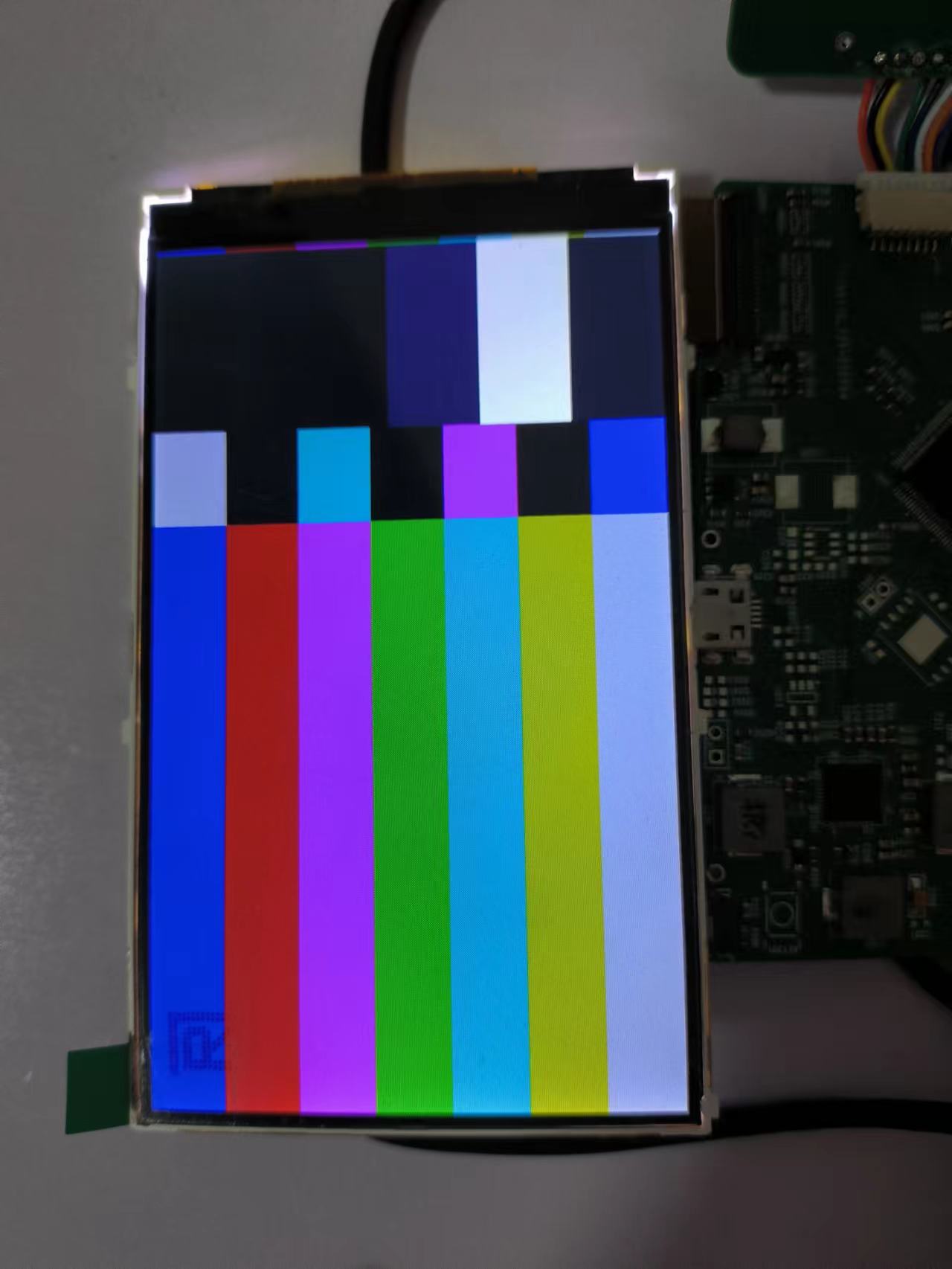
最近编辑记录 qianniao29 (2022-08-25 19:11:01)
离线
#1 2022-08-25 08:30:47 分享评论
- zhang235hai
- 会员
- 注册时间: 2020-04-06
- 已发帖子: 212
- 积分: 165
Re: [v3x][kernel5.13.9]NT35510 LCD液晶屏(RGB+SPI接口)DRM驱动调试
RGB调试呢?期待楼主分享
离线
楼主 #2 2022-08-25 19:20:17 分享评论
- qianniao29
- 会员
- 注册时间: 2020-05-19
- 已发帖子: 29
- 积分: 105.5
Re: [v3x][kernel5.13.9]NT35510 LCD液晶屏(RGB+SPI接口)DRM驱动调试
RGB调试呢?期待楼主分享
RGB接口主要是上面贴的驱动文件中的时序调整,前肩和后肩的时间参考了屏幕卖家提供的示例程序,设置的比示例大一些然后慢慢减小,找到合适的值。参照datasheet中的时序配置前肩和后肩,无法正常点亮,所以这个得慢慢调整。硬件布线也需要注意减小干扰,不然也会出问题。
还有在probe的时候配置drm模式为rgb,drm_panel_init(&nt->panel, dev, &nt35510_drm_funcs, DRM_MODE_CONNECTOR_DPI);
TCON和mixer在v3s.dtsi中已经有了,使能即可。
.mode = {
		/* The internal pixel clock of the NT35510 is 20 MHz */
		.clock = 25000,
		.hdisplay = 480,
		.hsync_start = 480 + 2, /* HFP = 2 */
		.hsync_end = 480 + 2 + 1, /* HSync = 0 */
		.htotal = 480 + 2 + 1 + 5, /* HBP = 5 */
		.vdisplay = 800,
		.vsync_start = 800 + 24, /* VFP = 2 */
		.vsync_end = 800 + 24 + 1, /* VSync = 0 */
		.vtotal = 800 + 24 + 1 + 5, /* VBP = 5 */
		.flags = 0,
	},
最近编辑记录 qianniao29 (2022-08-25 19:20:39)
离线
#3 2022-09-15 11:48:26 分享评论
- liutian
- 会员
- 注册时间: 2022-09-15
- 已发帖子: 5
- 积分: 0
Re: [v3x][kernel5.13.9]NT35510 LCD液晶屏(RGB+SPI接口)DRM驱动调试
楼主,请问只有spi连接的lcd是显示数据也走spi吗?也能init成DRM_MODE_CONNECTOR_DPI吗?
离线
#4 2022-09-15 11:54:13 分享评论
- varzhou
- 会员

- 注册时间: 2020-07-14
- 已发帖子: 108
- 积分: 2
Re: [v3x][kernel5.13.9]NT35510 LCD液晶屏(RGB+SPI接口)DRM驱动调试
drm方式和普通fb方式有多少资源优化? 瓶颈应该是spi速率吧
离线
楼主 #5 2022-09-19 14:52:07 分享评论
- qianniao29
- 会员
- 注册时间: 2020-05-19
- 已发帖子: 29
- 积分: 105.5
Re: [v3x][kernel5.13.9]NT35510 LCD液晶屏(RGB+SPI接口)DRM驱动调试
楼主,请问只有spi连接的lcd是显示数据也走spi吗?也能init成DRM_MODE_CONNECTOR_DPI吗?
应该不能吧,在tcon驱动部分还有部分drm对应的接口需要实现,只有spi的话,显示数据应该是用lcd的指令传输数据,也是走spi。spi屏可以用staging下的fbtft驱动。
离线
#7 2022-09-28 10:24:50 分享评论
- ronz
- 会员
- 注册时间: 2021-11-19
- 已发帖子: 31
- 积分: 31
Re: [v3x][kernel5.13.9]NT35510 LCD液晶屏(RGB+SPI接口)DRM驱动调试
楼主uboot用的什么版本?
离线
楼主 #8 2022-09-30 16:19:42 分享评论
- qianniao29
- 会员
- 注册时间: 2020-05-19
- 已发帖子: 29
- 积分: 105.5
Re: [v3x][kernel5.13.9]NT35510 LCD液晶屏(RGB+SPI接口)DRM驱动调试
楼主uboot用的什么版本?
buildroot编译的uboot-2021.01
离线
#9 2023-11-09 18:38:17 分享评论
- FH0
- 会员
- 注册时间: 2023-09-22
- 已发帖子: 6
- 积分: 6
Re: [v3x][kernel5.13.9]NT35510 LCD液晶屏(RGB+SPI接口)DRM驱动调试
楼主 NB。今天照着弄好了 himax 的 HX8347I 的 SPI+RGB 的屏幕。内核是主线的 6.6。u-boot 是主线的 v2023.10。buildroot 是主线的 2023.08.2。公司要用 Qt 开发一个简单的界面。
离线