楼主 #1 2020-11-03 10:37:22 分享评论
- xpf170702031
- 会员
- 注册时间: 2020-10-28
- 已发帖子: 11
- 积分: 11
F1C200S使用panel_simple驱动SPI+RGB液晶控制芯片
控制芯片型号ST7701S,接口使用
第一种方式:
1.使用panel-sitronix-st7789v.c仿造一个7701s出来,并且编译成模块
static const struct drm_display_mode default_mode = {
.clock = 27500,
.hdisplay = 960,
.hsync_start = 960 + 38,
.hsync_end = 960 + 38 + 12,
.htotal = 960 + 38 + 12 + 12,
.vdisplay = 320,
.vsync_start = 320 + 18,
.vsync_end = 320 + 18 + 8,
.vtotal = 320 + 18 + 8 + 4,
.vrefresh = 60,
};
static int st7789v_prepare(struct drm_panel *panel)
{
struct st7789v *ctx = panel_to_st7789v(panel);
int ret;
ret = regulator_enable(ctx->power);
if (ret)
return ret;
gpiod_set_value(ctx->reset, 1);
msleep(20);
gpiod_set_value(ctx->reset, 0);
msleep(20);
gpiod_set_value(ctx->reset, 1);
msleep(120);
/* We need to wait 120ms after a sleep out command */
ST7789V_TEST(ret, st7789v_write_command(ctx,0xff));
ST7789V_TEST(ret, st7789v_write_data(ctx, 0x77));
ST7789V_TEST(ret, st7789v_write_data(ctx, 0x01));
ST7789V_TEST(ret, st7789v_write_data(ctx, 0x00));
ST7789V_TEST(ret, st7789v_write_data(ctx, 0x00));
ST7789V_TEST(ret, st7789v_write_data(ctx, 0x13));
..........省略初始化命令和数据
dts修改(在spi设备节点里面增加):
st7701s@0x01 {
compatible = "sitronix,st7701s";
reg = <1>;
spi-max-frequency = <32000000>;
buswidth = <8>;
reset-gpios = <&pio 4 11 GPIO_ACTIVE_LOW>;
backlight = <&pwm_bl>;
status = "okay";
port {
panel_input: endpoint {
remote-endpoint = <&tcon0_out_lcd>;
};
};
};
结果:
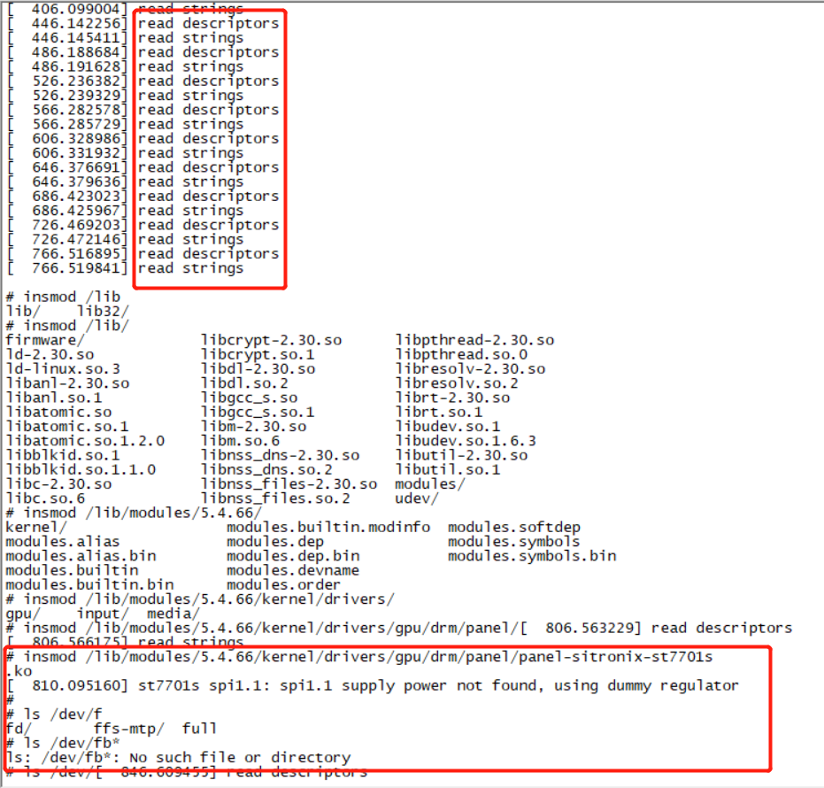
不能驱动出fb0,原因未知,请各路大神给点意见,分析分析
离线
楼主 #3 2020-11-03 19:23:29 分享评论
- xpf170702031
- 会员
- 注册时间: 2020-10-28
- 已发帖子: 11
- 积分: 11
Re: F1C200S使用panel_simple驱动SPI+RGB液晶控制芯片
前面那个方框应该是mtp服务程序导致usb的log,和这个没有关系。
建议挂逻辑分析仪看下时序对不对,
顺便把屏幕的手册上传一下,
是spi 9bit 下降沿吗?
是RGB+SPI 3线9bit 上升沿
芯片手册如下
https://whycan.com/files/members/5375/ST7701S_SPEC_%20V1_3.pdf
离线
楼主 #5 2020-12-05 16:42:31 分享评论
- xpf170702031
- 会员
- 注册时间: 2020-10-28
- 已发帖子: 11
- 积分: 11
Re: F1C200S使用panel_simple驱动SPI+RGB液晶控制芯片
我已经调试好了,用gpio模拟时序实现的,但是侧边界有2mm不能显示,不知道是不是要设置偏移量
离线
太原小智科技有限责任公司 - 东莞哇酷科技有限公司联合开发