楼主 # 2022-02-12 13:33:22 分享评论
- dianjixz
- 会员
- 注册时间: 2021-09-16
- 已发帖子: 9
- 积分: 13
D1 PD1&PD2引脚复用出现错误
最近使用 D1 时,想要使用 PD1&PD2 的串口复用功能.结果这个两个引脚一直在输出一个脉冲信号.改变了引脚复用关系寄存器后信号还在.
不知道是不是芯片自身的硬件引脚 bug.求大佬解答!
设备树引脚配置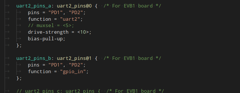
两个引脚输出的情况!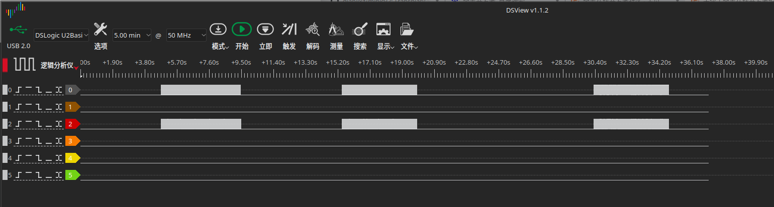
求有关大佬考证解答!
最近编辑记录 dianjixz (2022-02-12 13:36:50)
离线
楼主 #2 2022-02-12 14:12:35 分享评论
- dianjixz
- 会员
- 注册时间: 2021-09-16
- 已发帖子: 9
- 积分: 13
Re: D1 PD1&PD2引脚复用出现错误
卸掉 fb 模块后,引脚电平正常了.看样子是芯片的 disp 模块会强制在该引脚上输出一个信号.复用寄存器都屏蔽不掉这个信号.
比较坑的是,就算屏蔽了 fb 模块的设备树节点, D1 芯片的 disp 模块还是在工作,还是会输出一个信号.
简单的说就是 gpio 复用寄存器无法切断 disp 模块输出的信号.这是一大坑呀!
离线
楼主 #3 2022-02-12 14:47:02 分享评论
- dianjixz
- 会员
- 注册时间: 2021-09-16
- 已发帖子: 9
- 积分: 13
Re: D1 PD1&PD2引脚复用出现错误
情况并没有改善,开启 uart2 后,信号又出现了!
下面是设备树配置
/*
* Allwinner Technology CO., Ltd. sun20iw1p1 fpga.
*
* fpga support.
*/
/dts-v1/;
#include "sun20iw1p1.dtsi"
/{
compatible = "allwinner,d1", "arm,sun20iw1p1", "allwinner,sun20iw1p1";
aliases {
dsp0 = &dsp0;
dsp0_gpio_int= &dsp0_gpio_int;
};
mcp2515_clock: mcp2515_clock {
compatible = "fixed-clock";
#clock-cells = <0>;
clock-frequency = <8000000>;
};
reg_can_3v3: regulator@0 {
compatible = "regulator-fixed";
reg = <0>;
regulator-name = "can-3v3";
regulator-min-microvolt = <3300000>;
regulator-max-microvolt = <3300000>;
};
dsp0: dsp0 {
compatible = "allwinner,sun20iw1-dsp";
status = "okay";
};
dsp0_gpio_int: dsp0_gpio_int {
compatible = "allwinner,sun20iw1-dsp-gpio-int";
pin-group = "PB", "PC", "PD", "PE";
status = "disabled";
};
reg_vdd_cpu: vdd-cpu {
compatible = "sunxi-pwm-regulator";
pwms = <&pwm 0 5000 0>;
regulator-name = "vdd_cpu";
regulator-min-microvolt = <810000>;
regulator-max-microvolt = <1160000>;
regulator-ramp-delay = <25>;
regulator-always-on;
regulator-boot-on;
status = "okay";
};
reg_usb1_vbus: usb1-vbus {
compatible = "regulator-fixed";
regulator-name = "usb1-vbus";
regulator-min-microvolt = <5000000>;
regulator-max-microvolt = <5000000>;
regulator-enable-ramp-delay = <1000>;
gpio = <&pio PD 19 GPIO_ACTIVE_HIGH>;
enable-active-high;
};
};
&CPU0 {
cpu-supply = <®_vdd_cpu>;
};
&pio {
sdc0_pins_a: sdc0@0 {
allwinner,pins = "PF0", "PF1", "PF2",
"PF3", "PF4", "PF5";
allwinner,function = "sdc0";
allwinner,muxsel = <2>;
allwinner,drive = <3>;
allwinner,pull = <1>;
pins = "PF0", "PF1", "PF2",
"PF3", "PF4", "PF5";
function = "sdc0";
drive-strength = <30>;
bias-pull-up;
power-source = <3300>;
};
sdc0_pins_b: sdc0@1 {
pins = "PF0", "PF1", "PF2",
"PF3", "PF4", "PF5";
function = "sdc0";
drive-strength = <30>;
bias-pull-up;
power-source = <1800>;
};
sdc0_pins_c: sdc0@2 {
pins = "PF0", "PF1", "PF2",
"PF3", "PF4", "PF5";
function = "gpio_in";
};
/* TODO: add jtag pin */
sdc0_pins_d: sdc0@3 {
pins = "PF2", "PF4";
function = "uart0";
drive-strength = <10>;
bias-pull-up;
};
sdc0_pins_e: sdc0@4 {
pins = "PF0", "PF1", "PF3",
"PF5";
function = "jtag";
drive-strength = <10>;
bias-pull-up;
};
sdc1_pins_a: sdc1@0 {
pins = "PG0", "PG1", "PG2",
"PG3", "PG4", "PG5";
function = "sdc1";
drive-strength = <30>;
bias-pull-up;
};
sdc1_pins_b: sdc1@1 {
pins = "PG0", "PG1", "PG2",
"PG3", "PG4", "PG5";
function = "gpio_in";
};
sdc2_pins_a: sdc2@0 {
allwinner,pins = "PC2", "PC3", "PC4",
"PC5", "PC6", "PC7";
allwinner,function = "sdc2";
allwinner,muxsel = <3>;
allwinner,drive = <3>;
allwinner,pull = <1>;
pins = "PC2", "PC3", "PC4",
"PC5", "PC6", "PC7";
function = "sdc2";
drive-strength = <30>;
bias-pull-up;
};
sdc2_pins_b: sdc2@1 {
pins = "PC2", "PC3", "PC4",
"PC5", "PC6", "PC7";
function = "gpio_in";
};
wlan_pins_a:wlan@0 {
pins = "PG11";
function = "clk_fanout1";
};
uart0_pins_a: uart0_pins@0 { /* For nezha board */
pins = "PB8", "PB9";
function = "uart0";
drive-strength = <10>;
bias-pull-up;
};
uart0_pins_b: uart0_pins@1 { /* For nezha board */
pins = "PB8", "PB9";
function = "gpio_in";
};
uart1_pins_a: uart1_pins@0 { /* For EVB1 board */
pins = "PG6", "PG7", "PG8", "PG9";
function = "uart1";
drive-strength = <10>;
bias-pull-up;
};
uart1_pins_b: uart1_pins { /* For EVB1 board */
pins = "PG6", "PG7", "PG8", "PG9";
function = "gpio_in";
};
uart2_pins_a: uart2_pins@0 { /* For EVB1 board */
pins = "PD1", "PD2";
function = "uart2";
// muxsel = <5>;
// muxsel = <1>;
drive-strength = <10>;
bias-pull-up;
};
uart2_pins_b: uart2_pins@1 { /* For EVB1 board */
pins = "PD1", "PD2";
function = "gpio_in";
};
// uart2_pins_c: uart2_pins { /* For EVB1 board */
// pins = "PC1";
// function = "gpio_in";
// };
uart3_pins_a: uart3_pins@0 { /* For EVB1 board */
pins = "PC6", "PC7";
// pins = "PD10", "PD11";
function = "uart3";
muxsel = <4>;
// muxsel = <5>;
drive-strength = <10>;
bias-pull-up;
};
uart4_pins_a: uart4_pins@0 { /* For EVB1 board */
pins = "PB2", "PB3";
// pins = "PD10", "PD11";
function = "uart4";
muxsel = <7>;
// muxsel = <5>;
drive-strength = <10>;
bias-pull-up;
};
twi0_pins_a: twi0@0 {
pins = "PB10", "PB11"; /*sck sda*/
function = "twi0";
drive-strength = <10>;
};
twi0_pins_b: twi0@1 {
pins = "PB10", "PB11";
function = "gpio_in";
};
twi1_pins_a: twi1@0 {
pins = "PB4", "PB5";
function = "twi1";
drive-strength = <10>;
};
twi1_pins_b: twi1@1 {
pins = "PB4", "PB5";
function = "gpio_in";
};
twi2_pins_a: twi2@0 {
pins = "PB0", "PB1";
function = "twi2";
drive-strength = <10>;
};
twi2_pins_b: twi2@1 {
pins = "PB0", "PB1";
function = "gpio_in";
};
twi3_pins_a: twi3@0 {
pins = "PB6", "PB7";
function = "twi3";
drive-strength = <10>;
};
twi3_pins_b: twi3@1 {
pins = "PB6", "PB7";
function = "gpio_in";
};
gmac_pins_a: gmac@0 {
// pins = "PE0", "PE1", "PE2", "PE3",
// "PE4", "PE5", "PE6", "PE7",
// "PE8", "PE9", "PE10", "PE11",
// "PE12", "PE13", "PE14", "PE15";
pins = "PE0", "PE1", "PE2", "PE3",
"PE4", "PE5", "PE6", "PE7",
"PE8", "PE9";
function = "gmac0";
drive-strength = <10>;
};
gmac_pins_b: gmac@1 {
// pins = "PE0", "PE1", "PE2", "PE3",
// "PE4", "PE5", "PE6", "PE7",
// "PE8", "PE9", "PE10", "PE11",
// "PE12", "PE13", "PE14", "PE15";
pins = "PE0", "PE1", "PE2", "PE3",
"PE4", "PE5", "PE6", "PE7",
"PE8", "PE9";
function = "gpio_in";
};
// dmic_pins_a: dmic@0 {
// /* DMIC_PIN: CLK, DATA0, DATA1, DATA2 */
// pins = "PE17", "PB11", "PB10", "PD17";
// function = "dmic";
// drive-strength = <20>;
// bias-disable;
// };
// dmic_pins_b: dmic@1 {
// pins = "PE17", "PB11", "PB10", "PD17";
// function = "io_disabled";
// drive-strength = <20>;
// bias-disable;
// };
// daudio0_pins_a: daudio0@0 {
// pins = "PE17", "PE16", "PE15", "PE14", "PE13";
// function = "i2s0";
// drive-strength = <20>;
// bias-disable;
// };
// daudio0_pins_b: daudio0_sleep@0 {
// pins = "PE17", "PE16", "PE15", "PE14", "PE13";
// function = "io_disabled";
// drive-strength = <20>;
// bias-disable;
// };
// daudio1_pins_a: daudio1@0 {
// pins = "PG11", "PG12", "PG13", "PG14", "PG15";
// function = "i2s1";
// drive-strength = <20>;
// bias-disable;
// };
// daudio1_pins_b: daudio1_sleep@0 {
// pins = "PG11", "PG12", "PG13", "PG14", "PG15";
// function = "io_disabled";
// drive-strength = <20>;
// bias-disable;
// };
// daudio2_pins_a: daudio2@0 {
// /* I2S_PIN: MCLK, BCLK, LRCK */
// pins = "PB7", "PB5", "PB6";
// function = "i2s2";
// drive-strength = <20>;
// bias-disable;
// };
// daudio2_pins_b: daudio2@1 {
// /* I2S_PIN: DOUT0 */
// pins = "PB4";
// function = "i2s2_dout";
// drive-strength = <20>;
// bias-disable;
// };
// daudio2_pins_c: daudio2@2 {
// /* I2S_PIN: DIN0 */
// pins = "PB3";
// function = "i2s2_din";
// drive-strength = <20>;
// bias-disable;
// };
// daudio2_pins_d: daudio2_sleep@0 {
// pins = "PB7", "PB5", "PB6", "PB4", "PB3";
// function = "io_disabled";
// drive-strength = <20>;
// bias-disable;
// };
spdif_pins_a: spdif@0 {
/* SPDIF_PIN: SPDIF_OUT */
pins = "PB0";
function = "spdif";
drive-strength = <20>;
bias-disable;
};
spdif_pins_b: spdif_sleep@0 {
pins = "PB0";
function = "io_disabled";
drive-strength = <20>;
bias-disable;
};
spi0_pins_a: spi0@0 {
// pins = "PC2", "PC4", "PC5","PC7", "PC6"; /*clk mosi miso hold wp*/
pins = "PC2", "PC4", "PC5"; /*clk mosi miso hold wp*/
function = "spi0";
muxsel = <2>;
drive-strength = <10>;
};
spi0_pins_b: spi0@1 {
// pins = "PC3", "PC7", "PC6";
pins = "PC3";
function = "spi0";
muxsel = <2>;
drive-strength = <10>;
bias-pull-up; /* only CS should be pulled up */
};
spi0_pins_c: spi0@2 {
// pins = "PC2", "PC3", "PC4", "PC5","PC6", "PC7";
pins = "PC2", "PC3", "PC4", "PC5";
function = "gpio_in";
muxsel = <0>;
drive-strength = <10>;
};
can0_pins_a: can0@0 {
pins = "PD16";
function = "gpio_in";
muxsel = <0>;
drive-strength = <10>;
bias-pull-up;
};
spi1_pins_a: spi1@0 {
pins = "PD11", "PD12", "PD13","PD14", "PD15"; /*clk mosi miso hold wp*/
function = "spi1";
drive-strength = <10>;
};
spi1_pins_b: spi1@1 {
pins = "PD10";
function = "spi1";
drive-strength = <10>;
bias-pull-up; // only CS should be pulled up
};
spi1_pins_c: spi1@2 {
pins = "PD10", "PD11", "PD12", "PD13","PD14", "PD15";
function = "gpio_in";
drive-strength = <10>;
};
ledc_pins_a: ledc@0 {
pins = "PC0";
function = "ledc";
drive-strength = <10>;
};
ledc_pins_b: ledc@1 {
pins = "PC0";
function = "gpio_in";
};
pwm0_pin_a: pwm0@0 {
pins = "PD16";
function = "pwm0";
drive-strength = <10>;
bias-pull-up;
};
pwm0_pin_b: pwm0@1 {
pins = "PD16";
function = "gpio_in";
bias-disable;
};
pwm2_pin_a: pwm2@0 {
pins = "PD18";
function = "pwm2";
drive-strength = <10>;
bias-pull-up;
};
pwm2_pin_b: pwm2@1 {
pins = "PD18";
function = "gpio_in";
};
/*
pwm7_pin_a: pwm7@0 {
pins = "PD22";
function = "pwm7";
drive-strength = <10>;
bias-pull-up;
};
pwm7_pin_b: pwm7@1 {
pins = "PD22";
function = "gpio_in";
};
*/
s_cir0_pins_a: s_cir@0 {
pins = "PB12";
function = "ir";
drive-strength = <10>;
bias-pull-up;
};
s_cir0_pins_b: s_cir@1 {
pins = "PB12";
function = "gpio_in";
};
ir1_pins_a: ir1@0 {
pins = "PB0";
function = "ir";
drive-strength = <10>;
bias-pull-up;
};
ir1_pins_b: ir1@1 {
pins = "PB0";
function = "gpio_in";
};
};
&uart0 {
pinctrl-names = "default", "sleep";
pinctrl-0 = <&uart0_pins_a>;
pinctrl-1 = <&uart0_pins_b>;
status = "okay";
};
&uart1 {
pinctrl-names = "default", "sleep";
pinctrl-0 = <&uart1_pins_a>;
pinctrl-1 = <&uart1_pins_b>;
status = "okay";
};
echo 98 > /sys/class/gpio/export
echo "out" > /sys/class/gpio/gpio98/direction
echo 1 > /sys/class/gpio/gpio98/value
&uart2 {
pinctrl-names = "default", "sleep";
pinctrl-0 = <&uart2_pins_a>;
pinctrl-1 = <&uart2_pins_b>;
uart3_type = <2>;
status = "okay";
};
&uart3 {
/*compatible = "allwinner,sun20iw1-dsp-uart";*/
pinctrl-names = "default", "sleep";
pinctrl-0 = <&uart3_pins_a>;
pinctrl-1 = <&uart3_pins_a>;
uart3_type = <2>;
status = "okay";
};
&uart4 {
/*compatible = "allwinner,sun20iw1-dsp-uart";*/
pinctrl-names = "default", "sleep";
pinctrl-0 = <&uart4_pins_a>;
pinctrl-1 = <&uart4_pins_a>;
uart4_type = <2>;
status = "okay";
};
&soc {
card0_boot_para@2 {
/*
* Avoid dtc compiling warnings.
* @TODO: Developer should modify this to the actual value
*/
reg = <0x0 0x2 0x0 0x0>;
device_type = "card0_boot_para";
card_ctrl = <0x0>;
card_high_speed = <0x1>;
card_line = <0x4>;
pinctrl-0 = <&sdc0_pins_a>;
};
card2_boot_para@3 {
/*
* Avoid dtc compiling warnings.
* @TODO: Developer should modify this to the actual value
*/
reg = <0x0 0x3 0x0 0x0>;
device_type = "card2_boot_para";
card_ctrl = <0x2>;
card_high_speed = <0x1>;
card_line = <0x4>;
pinctrl-0 = <&sdc2_pins_a>;
/*pinctrl-0 = <&sdc0_pins_a>;*/
/*sdc_ex_dly_used = <0x2>;*/
sdc_io_1v8 = <0x1>;
/*sdc_type = "tm4";*/
sdc_tm4_hs200_max_freq = <150>;
sdc_tm4_hs400_max_freq = <100>;
sdc_ex_dly_used = <2>;
/*sdc_tm4_win_th = <8>;*/
/*sdc_dis_host_caps = <0x180>;*/
};
rfkill: rfkill@0 {
compatible = "allwinner,sunxi-rfkill";
chip_en;
power_en;
status = "okay";
wlan: wlan@0 {
compatible = "allwinner,sunxi-wlan";
pinctrl-0 = <&wlan_pins_a>;
pinctrl-names = "default";
clock-names = "32k-fanout1";
clocks = <&ccu CLK_FANOUT1_OUT>;
wlan_busnum = <0x1>;
wlan_regon = <&pio PG 12 GPIO_ACTIVE_HIGH>;
wlan_hostwake = <&pio PG 10 GPIO_ACTIVE_HIGH>;
/*wlan_power = "VCC-3V3";*/
/*wlan_power_vol = <3300000>;*/
/*interrupt-parent = <&pio>;
interrupts = < PG 10 IRQ_TYPE_LEVEL_HIGH>;*/
wakeup-source;
};
bt: bt@0 {
compatible = "allwinner,sunxi-bt";
pinctrl-0 = <&wlan_pins_a>;
pinctrl-names = "default";
clock-names = "32k-fanout1";
clocks = <&ccu CLK_FANOUT1_OUT>;
/*bt_power_num = <0x01>;*/
/*bt_power = "axp803-dldo1";*/
/*bt_io_regulator = "axp803-dldo1";*/
/*bt_io_vol = <3300000>;*/
/*bt_power_vol = <330000>;*/
bt_rst_n = <&pio PG 18 GPIO_ACTIVE_LOW>;
status = "okay";
};
};
btlpm: btlpm@0 {
compatible = "allwinner,sunxi-btlpm";
uart_index = <0x1>;
bt_wake = <&pio PG 16 GPIO_ACTIVE_HIGH>;
bt_hostwake = <&pio PG 17 GPIO_ACTIVE_HIGH>;
status = "okay";
};
addr_mgt: addr_mgt@0 {
compatible = "allwinner,sunxi-addr_mgt";
type_addr_wifi = <0x0>;
type_addr_bt = <0x0>;
type_addr_eth = <0x0>;
status = "okay";
};
};
&sdc2 {
non-removable;
bus-width = <4>;
mmc-ddr-1_8v;
mmc-hs200-1_8v;
no-sdio;
no-sd;
ctl-spec-caps = <0x308>;
cap-mmc-highspeed;
sunxi-power-save-mode;
sunxi-dis-signal-vol-sw;
mmc-bootpart-noacc;
max-frequency = <150000000>;
/*vmmc-supply = <®_dcdc1>;*/
/*emmc io vol 3.3v*/
/*vqmmc-supply = <®_aldo1>;*/
/*emmc io vol 1.8v*/
/*vqmmc-supply = <®_eldo1>;*/
status = "disabled";
};
&sdc0 {
bus-width = <4>;
cd-gpios = <&pio PF 6 (GPIO_ACTIVE_LOW | GPIO_PULL_UP)>;
/*non-removable;*/
/*broken-cd;*/
cd-inverted;
/*data3-detect;*/
/*card-pwr-gpios = <&pio PH 14 1 1 2 0xffffffff>;*/
cd-used-24M;
cap-sd-highspeed;
/*sd-uhs-sdr50;*/
/*sd-uhs-ddr50;*/
/*sd-uhs-sdr104;*/
no-sdio;
no-mmc;
sunxi-power-save-mode;
/*sunxi-dis-signal-vol-sw;*/
max-frequency = <150000000>;
ctl-spec-caps = <0x8>;
/*vmmc-supply = <®_dcdc1>;*/
/*vqmmc33sw-supply = <®_dcdc1>;*/
/*vdmmc33sw-supply = <®_dcdc1>;*/
/*vqmmc18sw-supply = <®_eldo1>;*/
/*vdmmc18sw-supply = <®_eldo1>;*/
status = "okay";
};
&sdc1 {
bus-width = <4>;
no-mmc;
no-sd;
cap-sd-highspeed;
/*sd-uhs-sdr12*/
/*sd-uhs-sdr25;*/
/*sd-uhs-sdr50;*/
/*sd-uhs-ddr50;*/
/*sd-uhs-sdr104;*/
/*sunxi-power-save-mode;*/
/*sunxi-dis-signal-vol-sw;*/
cap-sdio-irq;
keep-power-in-suspend;
ignore-pm-notify;
max-frequency = <150000000>;
ctl-spec-caps = <0x8>;
status = "okay";
};
/*
tvd configuration
used (create device, 0: do not create device, 1: create device)
agc_auto_enable (0: agc manual mode,agc_manual_value is valid; 1: agc auto mode)
agc_manual_value (agc manual value, default value is 64)
cagc_enable (cagc 0: disable, 1: enable)
fliter_used (3d fliter 0: disable, 1: enable)
support two PMU power (tvd_power0, tvd_power1)
support two GPIO power (tvd_gpio0, tvd_gpio1)
NOTICE: If tvd need pmu power or gpio power,params need be configured under [tvd]
tvd_sw (the switch of all tvd driver.)
tvd_interface (0: cvbs, 1: ypbpr,)
tvd_format (0:TVD_PL_YUV420 , 1: MB_YUV420, 2: TVD_PL_YUV422)
tvd_system (0:ntsc, 1:pal)
tvd_row (total row number in multi channel mode 1-2)
tvd_column (total column number in multi channel mode 1-2)
tvd_channelx_en (0:disable, 1~4:position in multi channel mode,In single channel
mode,mean enable)
tvd_row*tvd_column is the total tvd channel number to be used in multichannel mode
+--------------------+--------------------+
| | |
| | |
| 1 | 2 |
| | |
| | |
+--------------------+--------------------+
| | |
| | |
| 3 | 4 |
| | |
| | |
+--------------------+--------------------+
*/
// &tvd {
// tvd_sw = <1>;
// tvd_interface = <0>;
// tvd_format = <0>;
// tvd_system = <1>;
// tvd_row = <1>;
// tvd_column = <1>;
// tvd_channel0_en = <1>;
// tvd_channel1_en = <0>;
// tvd_channel2_en = <0>;
// tvd_channel3_en = <0>;
// /*tvd_gpio0 = <&pio PD 22 GPIO_ACTIVE_HIGH>;*/
// /*tvd_gpio1 = <&pio PD 23 GPIO_ACTIVE_HIGH>;*/
// /*tvd_gpio2 = <&pio PD 24 GPIO_ACTIVE_HIGH>;*/
// /* dc1sw-supply = <®_dc1sw>;*/
// /* eldo3-supply = <®_eldo3>;*/
// /*tvd_power0 = "dc1sw"*/
// /*tvd_power1 = "eldo3"*/
// };
// &tvd0 {
// used = <1>;
// agc_auto_enable = <1>;
// agc_manual_value = <64>;
// cagc_enable = <1>;
// fliter_used = <1>;
// };
/* Audio Driver modules */
&sunxi_rpaf_dsp0 {
status = "okay";
};
/* if audiocodec is used, sdc0 and uart0 should be closed to enable PA. */
&codec {
/* MIC and headphone gain setting */
mic1gain = <0x13>;
mic2gain = <0x13>;
mic3gain = <0x13>;
/* ADC/DAC DRC/HPF func enabled */
/* 0x1:DAP_HP_EN; 0x2:DAP_SPK_EN; 0x3:DAP_HPSPK_EN */
adcdrc_cfg = <0x0>;
adchpf_cfg = <0x1>;
dacdrc_cfg = <0x0>;
dachpf_cfg = <0x0>;
/* Volume about */
digital_vol = <0x00>;
lineout_vol = <0x1a>;
headphonegain = <0x03>;
/* Pa enabled about */
pa_level = <0x01>;
pa_pwr_level = <0x01>;
pa_msleep_time = <0x78>;
/* gpio-spk = <&pio PF 2 GPIO_ACTIVE_HIGH>; */
/* gpio-spk-pwr = <&pio PF 4 GPIO_ACTIVE_HIGH>; */
/* regulator about */
/* avcc-supply = <®_aldo1>; */
/* hpvcc-supply = <®_eldo1>; */
status = "okay";
};
// &sndcodec {
// hp_detect_case = <0x01>;
// jack_enable = <0x01>;
// status = "okay";
// };
&dummy_cpudai {
/* CMA config about */
playback_cma = <128>;
capture_cma = <256>;
status = "okay";
};
// &dmic {
// pinctrl-names = "default","sleep";
// pinctrl-0 = <&dmic_pins_a>;
// pinctrl-1 = <&dmic_pins_b>;
// status = "okay";
// };
// &sounddmic {
// status = "okay";
// };
// &dmic_codec {
// status = "okay";
// };
/*-----------------------------------------------------------------------------
* pcm_lrck_period 16/32/64/128/256
* (set 0x20 for HDMI audio out)
* slot_width_select 16bits/20bits/24bits/32bits
* (set 0x20 for HDMI audio out)
* frametype 0 --> short frame = 1 clock width;
* 1 --> long frame = 2 clock width;
* tdm_config 0 --> pcm
* 1 --> i2s
* (set 0x01 for HDMI audio out)
* mclk_div 0 --> not output
* 1/2/4/6/8/12/16/24/32/48/64/96/128/176/192
* (set mclk as external codec clk source, freq is pll_audio/mclk_div)
* pinctrl_used 0 --> I2S/PCM use for internal (e.g. HDMI)
* 1 --> I2S/PCM use for external audio
* daudio_type: 0 --> external audio type
* 1 --> HDMI audio type
*---------------------------------------------------------------------------*/
// &daudio0 {
// mclk_div = <0x01>;
// frametype = <0x00>;
// tdm_config = <0x01>;
// sign_extend = <0x00>;
// msb_lsb_first = <0x00>;
// pcm_lrck_period = <0x80>;
// slot_width_select = <0x20>;
// pinctrl-names = "default", "sleep";
// pinctrl-0 = <&daudio0_pins_a>;
// pinctrl-1 = <&daudio0_pins_b>;
// pinctrl_used = <0x0>;
// status = "disabled";
// };
/*-----------------------------------------------------------------------------
* simple-audio-card,name name of sound card, e.g.
* "snddaudio0" --> use for external audio
* "sndhdmi" --> use for HDMI audio
* sound-dai "snd-soc-dummy" --> use for I2S
* "hdmiaudio" --> use for HDMI audio
* "ac108" --> use for external audio of ac108
*---------------------------------------------------------------------------*/
// &sounddaudio0 {
// /* simple-audio-card,format = "i2s"; */
// /* simple-audio-card,frame-master = <&daudio0_master>; */
// /* simple-audio-card,bitclock-master = <&daudio0_master>; */
// /* simple-audio-card,bitclock-inversion; */
// /* simple-audio-card,frame-inversion; */
// status = "disabled";
// daudio0_master: simple-audio-card,codec {
// /* sound-dai = <&ac108>; */
// };
// };
// &daudio1 {
// mclk_div = <0x01>;
// frametype = <0x00>;
// tdm_config = <0x01>;
// sign_extend = <0x00>;
// msb_lsb_first = <0x00>;
// pcm_lrck_period = <0x80>;
// slot_width_select = <0x20>;
// pinctrl-names = "default", "sleep";
// pinctrl-0 = <&daudio1_pins_a>;
// pinctrl-1 = <&daudio1_pins_b>;
// pinctrl_used = <0x0>;
// status = "disabled";
// };
// &sounddaudio1 {
// status = "disabled";
// daudio1_master: simple-audio-card,codec {
// /* sound-dai = <&ac108>; */
// };
// };
// &daudio2 {
// mclk_div = <0x00>;
// frametype = <0x00>;
// tdm_config = <0x01>;
// sign_extend = <0x00>;
// tx_data_mode = <0x00>;
// rx_data_mode = <0x00>;
// msb_lsb_first = <0x00>;
// pcm_lrck_period = <0x20>;
// slot_width_select = <0x20>;
// asrc_function_en = <0x00>;
// pinctrl-names = "default", "sleep";
// /*pinctrl-0 = <&daudio2_pins_a &daudio2_pins_b &daudio2_pins_c>;*/
// /*pinctrl-1 = <&daudio2_pins_d>;*/
// /* HDMI audio, no need pin */
// pinctrl-0;
// pinctrl-1;
// pinctrl_used = <0x0>;
// daudio_type = <0x1>;
// status = "okay";
// };
/* if HDMI audio is used, daudio2 should be enable. */
// &hdmiaudio {
// status = "okay";
// };
// &sounddaudio2 {
// status = "okay";
// simple-audio-card,name = "sndhdmi";
// daudio2_master: simple-audio-card,codec {
// sound-dai = <&hdmiaudio>;
// };
// };
&spdif {
pinctrl-names = "default","sleep";
pinctrl-0 = <&spdif_pins_a>;
pinctrl-1 = <&spdif_pins_b>;
status = "disabled";
};
// &soundspdif {
// status = "disabled";
// };
/*
*usb_port_type: usb mode. 0-device, 1-host, 2-otg.
*usb_detect_type: usb hotplug detect mode. 0-none, 1-vbus/id detect, 2-id/dpdm detect.
*usb_detect_mode: 0-thread scan, 1-id gpio interrupt.
*usb_id_gpio: gpio for id detect.
*usb_det_vbus_gpio: gpio for id detect. gpio or "axp_ctrl";
*usb_wakeup_suspend:0-SUPER_STANDBY, 1-USB_STANDBY.
*/
&usbc0 {
device_type = "usbc0";
usb_port_type = <0x2>;
usb_detect_type = <0x1>;
usb_detect_mode = <0>;
usb_id_gpio = <&pio PD 21 GPIO_ACTIVE_HIGH>;
enable-active-high;
usb_det_vbus_gpio = <&pio PD 20 GPIO_ACTIVE_HIGH>;
usb_wakeup_suspend = <0>;
usb_serial_unique = <0>;
usb_serial_number = "20080411";
rndis_wceis = <1>;
status = "okay";
};
&ehci0 {
drvvbus-supply = <®_usb1_vbus>;
};
&ohci0 {
drvvbus-supply = <®_usb1_vbus>;
};
&usbc1 {
device_type = "usbc1";
usb_regulator_io = "nocare";
usb_wakeup_suspend = <0>;
status = "okay";
};
&ehci1 {
status = "okay";
};
&ohci1 {
status = "okay";
};
&twi0 {
clock-frequency = <400000>;
pinctrl-0 = <&twi0_pins_a>;
pinctrl-1 = <&twi0_pins_b>;
pinctrl-names = "default", "sleep";
status = "disabled";
eeprom@50 {
compatible = "atmel,24c16";
reg = <0x50>;
status = "disabled";
};
};
&twi1 {
clock-frequency = <400000>;
pinctrl-0 = <&twi1_pins_a>;
pinctrl-1 = <&twi1_pins_b>;
pinctrl-names = "default", "sleep";
status = "disabled";
};
&twi2 {
clock-frequency = <400000>;
pinctrl-0 = <&twi2_pins_a>;
pinctrl-1 = <&twi2_pins_b>;
pinctrl-names = "default", "sleep";
dmas = <&dma 45>, <&dma 45>;
dma-names = "tx", "rx";
status = "okay";
/* pcf8574-usage:
* only use gpio0~7, 0 means PP0.
* pin set:
* gpios = <&pcf8574 0 GPIO_ACTIVE_LOW>;
* interrupt set:
* interrupt-parent = <&pcf8574>;
* interrupts = <0 IRQ_TYPE_EDGE_FALLING>;
*/
pcf8574: gpio@38 {
compatible = "nxp,pcf8574";
reg = <0x38>;
gpio_base = <2020>;
gpio-controller;
#gpio-cells = <2>;
interrupt-controller;
#interrupt-cells = <2>;
interrupt-parent = <&pio>;
interrupts = <PB 2 IRQ_TYPE_EDGE_FALLING>;
status = "okay";
};
ctp@14 {
compatible = "allwinner,goodix";
device_type = "ctp";
reg = <0x14>;
status = "disabled";
ctp_name = "gt9xxnew_ts";
ctp_twi_id = <0x2>;
ctp_twi_addr = <0x14>;
ctp_screen_max_x = <0x320>;
ctp_screen_max_y = <0x500>;
ctp_revert_x_flag = <0x0>;
ctp_revert_y_flag = <0x0>;
ctp_exchange_x_y_flag = <0x0>;
ctp_int_port = <&pio PG 14 GPIO_ACTIVE_HIGH>;
ctp_wakeup = <&pio PG 15 GPIO_ACTIVE_HIGH>;
};
};
&twi3 {
clock-frequency = <400000>;
pinctrl-0 = <&twi3_pins_a>;
pinctrl-1 = <&twi3_pins_b>;
pinctrl-names = "default", "sleep";
status = "disabled";
};
&gmac0 {
phy-mode = "rmii";
use_ephy25m = <1>;
pinctrl-0 = <&gmac_pins_a>;
pinctrl-1 = <&gmac_pins_b>;
pinctrl-names = "default", "sleep";
phy-rst = <&pio PE 16 GPIO_ACTIVE_HIGH>;
tx-delay = <7>; /*2~4*/
rx-delay = <31>;
status = "okay";
};
&spi0 {
clock-frequency = <100000000>;
pinctrl-0 = <&spi0_pins_a &spi0_pins_b>;
pinctrl-1 = <&spi0_pins_c>;
pinctrl-names = "default", "sleep";
/*spi-supply = <®_dcdc1>;*/
spi_slave_mode = <0>;
spi0_cs_number = <1>;
spi0_cs_bitmap = <1>;
status = "okay";
// spi-nand@0 {
// compatible = "spi-nand";
// spi-max-frequency=<0x5F5E100>;
// reg = <0x0>;
// spi-rx-bus-width=<0x04>;
// spi-tx-bus-width=<0x04>;
// status="disabled";
// };
can0@0 {
compatible = "microchip,mcp2515";
spi-max-frequency=<0x989680>;
reg = <0>;
spi-rx-bus-width=<0x04>;
spi-tx-bus-width=<0x04>;
pinctrl-0 = <&can0_pins_a>;
pinctrl-1 = <&can0_pins_a>;
pinctrl-names = "default", "sleep";
clocks = <&mcp2515_clock>;
interrupt-parent = <&pio>;
interrupts = <PD 16 IRQ_TYPE_EDGE_FALLING>;
vdd-supply = <®_pio3_3>;
xceiver-supply = <®_pio3_3>;
status = "okay";
};
};
&spi1 {
clock-frequency = <100000000>;
pinctrl-0 = <&spi1_pins_a &spi1_pins_b>;
pinctrl-1 = <&spi1_pins_c>;
pinctrl-names = "default", "sleep";
spi_slave_mode = <0>;
status = "disabled";
// spi_board1@0 {
// device_type = "spi_board1";
// compatible = "rohm,dh2228fv";
// spi-max-frequency = <0x5f5e100>;
// reg = <0x0>;
// spi-rx-bus-width = <0x4>;
// spi-tx-bus-width = <0x4>;
// status = "disabled";
// };
};
&ledc {
pinctrl-names = "default", "sleep";
pinctrl-0 = <&ledc_pins_a>;
pinctrl-1 = <&ledc_pins_b>;
led_count = <12>;
output_mode = "GRB";
reset_ns = <84>;
t1h_ns = <800>;
t1l_ns = <320>;
t0h_ns = <300>;
t0l_ns = <800>;
wait_time0_ns = <84>;
wait_time1_ns = <84>;
wait_data_time_ns = <600000>;
status = "okay";
};
&keyboard0 {
key0 = <210 0x160>;
wakeup-source;
status = "okay";
};
/*----------------------------------------------------------------------------------
disp init configuration
disp_mode (0:screen0<screen0,fb0>)
screenx_output_type (0:none; 1:lcd; 2:tv; 3:hdmi;5:vdpo)
screenx_output_mode (used for hdmi output, 0:480i 1:576i 2:480p 3:576p 4:720p50)
(5:720p60 6:1080i50 7:1080i60 8:1080p24 9:1080p50 10:1080p60)
screenx_output_format (for hdmi, 0:RGB 1:yuv444 2:yuv422 3:yuv420)
screenx_output_bits (for hdmi, 0:8bit 1:10bit 2:12bit 2:16bit)
screenx_output_eotf (for hdmi, 0:reserve 4:SDR 16:HDR10 18:HLG)
screenx_output_cs (for hdmi, 0:undefined 257:BT709 260:BT601 263:BT2020)
screenx_output_dvi_hdmi (for hdmi, 0:undefined 1:dvi mode 2:hdmi mode)
screen0_output_range (for hdmi, 0:default 1:full 2:limited)
screen0_output_scan (for hdmi, 0:no data 1:overscan 2:underscan)
screen0_output_aspect_ratio (for hdmi, 8-same as original picture 9-4:3 10-16:9 11-14:9)
fbx format (4:RGB655 5:RGB565 6:RGB556 7:ARGB1555 8:RGBA5551 9:RGB888 10:ARGB8888 12:ARGB4444)
fbx pixel sequence (0:ARGB 1:BGRA 2:ABGR 3:RGBA)
fb0_scaler_mode_enable(scaler mode enable, used FE)
fbx_width,fbx_height (framebuffer horizontal/vertical pixels, fix to output resolution while equal 0)
lcdx_backlight (lcd init backlight,the range:[0,256],default:197
lcdx_yy (lcd init screen bright/contrast/saturation/hue, value:0~100, default:50/50/57/50)
lcd0_contrast (LCD contrast, 0~100)
lcd0_saturation (LCD saturation, 0~100)
lcd0_hue (LCD hue, 0~100)
framebuffer software rotation setting:
disp_rotation_used: (0:disable; 1:enable,you must set fbX_width to lcd_y,
set fbX_height to lcd_x)
degreeX: (X:screen index; 0:0 degree; 1:90 degree; 3:270 degree)
degreeX_Y: (X:screen index; Y:layer index 0~15; 0:0 degree; 1:90 degree; 3:270 degree)
devX_output_type : config output type in bootGUI framework in UBOOT-2018.
(0:none; 1:lcd; 2:tv; 4:hdmi;)
devX_output_mode : config output resolution(see include/video/sunxi_display2.h) of bootGUI framework in UBOOT-2018
devX_screen_id : config display index of bootGUI framework in UBOOT-2018
devX_do_hpd : whether do hpd detectation or not in UBOOT-2018
chn_cfg_mode : Hardware DE channel allocation config. 0:single display with 6
channel, 1:dual display with 4 channel in main display and 2 channel in second
display, 2:dual display with 3 channel in main display and 3 channel in second
in display.
----------------------------------------------------------------------------------*/
// &disp {
// disp_init_enable = <1>;
// disp_mode = <0>;
// screen0_output_type = <1>;
// screen0_output_mode = <4>;
// screen1_output_type = <3>;
// screen1_output_mode = <10>;
// screen1_output_format = <0>;
// screen1_output_bits = <0>;
// screen1_output_eotf = <4>;
// screen1_output_cs = <257>;
// screen1_output_dvi_hdmi = <2>;
// screen1_output_range = <2>;
// screen1_output_scan = <0>;
// screen1_output_aspect_ratio = <8>;
// dev0_output_type = <1>;
// dev0_output_mode = <4>;
// dev0_screen_id = <0>;
// dev0_do_hpd = <0>;
// dev1_output_type = <4>;
// dev1_output_mode = <10>;
// dev1_screen_id = <1>;
// dev1_do_hpd = <1>;
// def_output_dev = <0>;
// hdmi_mode_check = <1>;
// fb0_format = <0>;
// fb0_width = <0>;
// fb0_height = <0>;
// fb1_format = <0>;
// fb1_width = <0>;
// fb1_height = <0>;
// chn_cfg_mode = <1>;
// disp_para_zone = <1>;
// /*VCC-LCD*/
// /* dc1sw-supply = <®_dc1sw>;*/
// /*VCC-DSI*/
// /* eldo3-supply = <®_eldo3>;*/
// /*VCC-PD*/
// /* dcdc1-supply = <®_dcdc1>;*/
// };
/*----------------------------------------------------------------------------------
;lcd0 configuration
;lcd_if: 0:hv(sync+de); 1:8080; 2:ttl; 3:lvds; 4:dsi; 5:edp; 6:extend dsi
;lcd_hv_if 0:Parallel RGB; 8:Serial RGB; 10:Dummy RGB; 11: RGB Dummy;12:CCIR656
;lcd_hv_clk_phase 0:0 degree;1:90 degree;2:180 degree;3:270 degree
;lcd_hv_sync_polarity 0:vs low,hs low; 1:vs high,hslow; 2:vs low,hs high; 3:vs high,hs high
;lcd_hv_syuv_seq 0:YUYV; 1:YVYU; 2:UYVY; 3:VYUY
;lcd_cpu_if 0:18bit/1 cycle parallel(RGB666); 4:16bit/1cycle parallel (RGB565)
; 6:18bit/3 cycle parallel(RGB666); 7:16bit/2cycle parallel (RGB565)
;lcd_cpu_te 0:frame auto trigger; 1:frame triggered by te rising edge; 2:frame triggered by te falling edge;
;lcd_dsi_if 0:video mode; 1: Command mode; 2:video burst mode
;lcd_dsi_te 0:frame auto trigger; 1:frame triggered by te rising edge; 2:frame triggered by te falling edge;
;lcd_x: lcd horizontal resolution
;lcd_y: lcd vertical resolution
;lcd_width: width of lcd in mm
;lcd_height: height of lcd in mm
;lcd_dclk_freq: in MHZ unit
;lcd_pwm_freq: in HZ unit
;lcd_pwm_pol: lcd backlight PWM polarity
;lcd_pwm_max_limit lcd backlight PWM max limit(<=255)
;lcd_hbp: hsync back porch(pixel) + hsync plus width(pixel);
;lcd_ht: hsync total cycle(pixel)
;lcd_vbp: vsync back porch(line) + vysnc plus width(line)
;lcd_vt: vysnc total cycle(line)
;lcd_hspw: hsync plus width(pixel)
;lcd_vspw: vysnc plus width(pixel)
;lcd_lvds_if: 0:single link; 1:dual link
;lcd_lvds_colordepth: 0:8bit; 1:6bit
;lcd_lvds_mode: 0:NS mode; 1:JEIDA mode
;lcd_frm: 0:disable; 1:enable rgb666 dither; 2:enable rgb656 dither
;lcd_io_phase: 0:noraml; 1:intert phase(0~3bit: vsync phase; 4~7bit:hsync phase;
; 8~11bit:dclk phase; 12~15bit:de phase)
;lcd_gamma_en lcd gamma correction enable
;lcd_bright_curve_en lcd bright curve correction enable
;lcd_cmap_en lcd color map function enable
;deu_mode 0:smoll lcd screen; 1:large lcd screen(larger than 10inch)
;lcdgamma4iep: Smart Backlight parameter, lcd gamma vale * 10;
; decrease it while lcd is not bright enough; increase while lcd is too bright
;smart_color 90:normal lcd screen 65:retina lcd screen(9.7inch)
;Pin setting for special function ie.LVDS, RGB data or vsync
; name(donot care) = port:PD12<pin function><pull up or pull down><drive ability><output level>
;Pin setting for gpio:
; lcd_gpio_X = port:PD12<pin function><pull up or pull down><drive ability><output level>
;Pin setting for backlight enable pin
; lcd_bl_en = port:PD12<pin function><pull up or pull down><drive ability><output level>
;fsync setting, pulse to csi
;lcd_fsync_en (0:disable fsync,1:enable)
;lcd_fsync_act_time (active time of fsync, unit:pixel)
;lcd_fsync_dis_time (disactive time of fsync, unit:pixel)
;lcd_fsync_pol (0:positive;1:negative)
;gpio config: <&pio for cpu or &r_pio for cpus, port, port num, pio function,
pull up or pull down(default 0), driver level(default 1), data>
;For dual link lvds: use lvds2link_pins_a and lvds2link_pins_b instead
;For rgb24: use rgb24_pins_a and rgb24_pins_b instead
;For lvds1: use lvds1_pins_a and lvds1_pins_b instead
;For lvds0: use lvds0_pins_a and lvds0_pins_b instead
;----------------------------------------------------------------------------------*/
// &lcd0 {
// lcd_used = <1>;
// lcd_driver_name = "tft08006";
// lcd_backlight = <100>;
// lcd_if = <4>;
// lcd_x = <800>;
// lcd_y = <1280>;
// lcd_width = <52>;
// lcd_height = <52>;
// lcd_dclk_freq = <70>;
// lcd_pwm_used = <1>;
// lcd_pwm_ch = <2>;
// lcd_pwm_freq = <1000>;
// lcd_pwm_pol = <0>;
// lcd_pwm_max_limit = <255>;
// lcd_hbp = <32>;
// lcd_ht = <868>;
// lcd_hspw = <4>;
// lcd_vbp = <12>;
// lcd_vt = <1311>;
// lcd_vspw = <4>;
// lcd_dsi_if = <0>;
// lcd_dsi_lane = <4>;
// lcd_lvds_if = <0>;
// lcd_lvds_colordepth = <0>;
// lcd_lvds_mode = <0>;
// lcd_frm = <0>;
// lcd_hv_clk_phase = <0>;
// lcd_hv_sync_polarity= <0>;
// lcd_io_phase = <0x0000>;
// lcd_gamma_en = <0>;
// lcd_bright_curve_en = <0>;
// lcd_cmap_en = <0>;
// lcd_fsync_en = <0>;
// lcd_fsync_act_time = <1000>;
// lcd_fsync_dis_time = <1000>;
// lcd_fsync_pol = <0>;
// deu_mode = <0>;
// lcdgamma4iep = <22>;
// smart_color = <90>;
// lcd_gpio_0 = <&pio PG 13 GPIO_ACTIVE_HIGH>;
// pinctrl-0 = <&dsi4lane_pins_a>;
// pinctrl-1 = <&dsi4lane_pins_b>;
// status = "disabled"; //-------------------------------------add
// };
// &hdmi {
// hdmi_used = <1>;
// hdmi_power_cnt = <0>;
// hdmi_cts_compatibility = <1>;
// hdmi_hdcp_enable = <1>;
// hdmi_hdcp22_enable = <0>;
// hdmi_cec_support = <1>;
// hdmi_cec_super_standby = <0>;
// ddc_en_io_ctrl = <0>;
// power_io_ctrl = <0>;
// status = "disabled"; //-------------------------------------add
// };
&pwm0 {
pinctrl-names = "active", "sleep";
pinctrl-0 = <&pwm0_pin_a>;
pinctrl-1 = <&pwm0_pin_b>;
status = "okay";
};
&pwm2 {
pinctrl-names = "active", "sleep";
pinctrl-0 = <&pwm2_pin_a>;
pinctrl-1 = <&pwm2_pin_b>;
status = "okay";
};
/*
&pwm7 {
pinctrl-names = "active", "sleep";
pinctrl-0 = <&pwm7_pin_a>;
pinctrl-1 = <&pwm7_pin_b>;
status = "okay";
};
*/
&rtp {
allwinner,tp-sensitive-adjust = <0xf>;
allwinner,filter-type = <0x1>;
allwinner,ts-attached;
status = "disabled";
};
&gpadc {
channel_num = <2>;
channel_select = <3>;
channel_data_select = <3>;
channel_compare_select = <3>;
channel_cld_select = <3>;
channel_chd_select = <3>;
channel0_compare_lowdata = <1700000>;
channel0_compare_higdata = <1200000>;
channel1_compare_lowdata = <460000>;
channel1_compare_higdata = <1200000>;
status = "disabled";
};
&s_cir0 {
pinctrl-names = "default", "sleep";
pinctrl-0 = <&s_cir0_pins_a>;
pinctrl-1 = <&s_cir0_pins_b>;
status = "disabled";
};
&ir1 {
pinctrl-names = "default", "sleep";
pinctrl-0 = <&ir1_pins_a>;
pinctrl-1 = <&ir1_pins_b>;
status = "disabled";
};离线
楼主 #5 2022-02-14 10:28:11 分享评论
- dianjixz
- 会员
- 注册时间: 2021-09-16
- 已发帖子: 9
- 积分: 13
Re: D1 PD1&PD2引脚复用出现错误
是全志芯片的一个隐藏问题,全志的 tcon 模块上电后会自己运行,然后在 PD 接口上发送信号.同时全志的 GPIO 引脚复用关系寄存器无法切断 tcon 信号的输出.我试过操作 PD_CFG0 寄存器,但是没有用.最后是无意中发现只要在全志的框架下关闭显示功能才能彻底停掉 tcon 信号.这个在使用 PD 组 复用 GPIO 时需要注意的问题.目前不知道全志 D1 裸机情况下会不会出现这个问题.期望开发全志 D1 裸机的大佬验证下这个问题.
离线
#6 2022-02-14 10:33:35 分享评论
- tigger
- Moderator
- 注册时间: 2021-06-18
- 已发帖子: 172
- 积分: 111
Re: D1 PD1&PD2引脚复用出现错误
@dianjixz
这就尴尬了。。。
离线
#7 2022-06-01 14:25:57 分享评论
- yang_AE86
- 会员
- 注册时间: 2021-10-19
- 已发帖子: 18
- 积分: 14
Re: D1 PD1&PD2引脚复用出现错误
请问楼主,这个问题解决了吗
离线
#8 2022-06-01 14:26:44 分享评论
- yang_AE86
- 会员
- 注册时间: 2021-10-19
- 已发帖子: 18
- 积分: 14
Re: D1 PD1&PD2引脚复用出现错误
关了内核模块,但是开启串口后,可以正常工作吗?
离线
感谢为中文互联网持续输出优质内容的各位老铁们。
QQ: 516333132, 微信(wechat): whycan_cn (哇酷网/挖坑网/填坑网) service@whycan.cn
东莞哇酷科技有限公司开发
东莞哇酷科技有限公司开发