- 首页
- » 搜索
- » xbgzy 发表的帖子
页次: 1
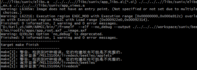
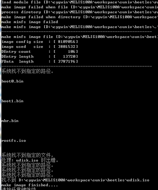
#1 全志 SOC » 打包melis出错 » 2019-10-29 17:49:19
#2 Re: 全志 SOC » LicheePi Nano 开机显示异常 » 2019-10-22 18:52:09
#3 Re: 全志 SOC » nano linux内核启动后花屏 » 2019-10-20 12:40:01
晕哥 wrote:
这个花不花: 15. 分享一个 5寸的 800x480 的 f1c100s 固件, 感谢 @xm1994
只需要替换zImage文件吗?我是tf卡启动
#4 Re: 全志 SOC » nano linux内核启动后花屏 » 2019-10-20 12:34:38
#5 全志 SOC » nano linux内核启动后花屏 » 2019-10-20 12:15:24
- xbgzy
- 回复: 5
用的荔枝派 NANO tf卡镜像文件,uboot用的我编译的,内核是f1c100s-480272lcd-test,内核编译使用的默认参数,根文件系统没有动,用的lcd分辨率240*320,在uboot里修改了lcd参数,编译后替换tf卡分区内的zImage和dtb。启动后uboot阶段显示logo正常,但一旦Starting kernel 就开始花屏,如下图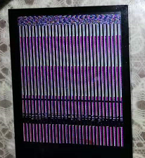
bootarg是console=tty0 console=ttyS0,115200 panic=5 rootwait root=/dev/mmcblk0p2 rw
bootcmd使用的是缺省值run distro_bootcmd
内核设备树,lcd部分:
panel: panel {
compatible = "qiaodian,qd43003c0-40", "simple-panel";
#address-cells = <1>;
#size-cells = <0>;
enable-gpios = <&pio 4 6 GPIO_ACTIVE_HIGH>;
port@0 {
reg = <0>;
#address-cells = <1>;
#size-cells = <0>;
panel_input: endpoint@0 {
reg = <0>;
remote-endpoint = <&tcon0_out_lcd>;
};
};
};
我想请教一下,内核里是不是也要修改lcd参数,比如x:,y:,depth:,pclk_khz:,le:等参数?感觉像是Uboot传递给内核的lcd参数不对?还是说内核的logo是480272,显示在240320上才花屏?
#6 Re: 全志 SOC » tf卡启动nano,自己编译的uboot替换后无法启动内核 » 2019-10-18 16:33:20
好的谢谢,我学习一下
#8 Re: 全志 SOC » tf卡启动nano,自己编译的uboot替换后无法启动内核 » 2019-10-18 16:01:52
晕哥 wrote:
可以在 include/configs/suniv.h 设置 CONFIG_BOOTCOMMAND/ CONFIG_BOOTARGS
提示重复定义的的话, 可以先 #undef CONFIG_BOOTCOMMAND, 然后再 #define CONFIG_BOOTCOMMAND
不建议使用这个方法可以在make menuconfig 里面配置 bootargs/bootcmd
boot.scr 可以设置 bootargs/bootcmd
嗯,我请教一下,我看你在论坛里有个v3s tf启动盘的帖子,里面有bootargs/bootcmd的配置:
#define CONFIG_BOOTARGS        "console=ttyS0,115200 panic=5 rootwait mtdparts=spi32766.0:1M(uboot)ro,64k(dtb)ro,6M(kernel)ro,-(rootfs) root=/dev/mmcblk0p2 earlyprintk rw"
#define CONFIG_BOOTCOMMAND \
    "setenv bootm_boot_mode sec; " \
    "load mmc 0:1 0x41000000 zImage; " \
    "load mmc 0:1 0x41800000 sun8i-v3s-licheepi-zero-dock.dtb;" \
    "bootz 0x41000000 - 0x41800000; "
如果要用在nano上,我要修改哪些地方呢?
#9 Re: 全志 SOC » f1c100s驱动st7789v的问题 » 2019-10-18 15:27:04
#10 Re: 全志 SOC » tf卡启动nano,自己编译的uboot替换后无法启动内核 » 2019-10-18 15:24:37
晕哥 wrote:
看下 u-boot 源码下面的 include/configs/suniv.h
有没有 bootargs, bootcmd 相关的代码。
晕哥你好,在suniv.h我试过添加bootargs和bootcmd,bootargs内容和boot.scr一样“console=tty0 console=ttyS0,115200 panic=5 rootwait root=/dev/mmcblk0p2 rw”;而且只要我定义了bootcmd编译会报错说有重复定义,现在我自己电脑不在身边,暂时没有办法截图说明。晕哥我请教一下,tf启动bootcmd部分应该怎么定义?
#11 全志 SOC » tf卡启动nano,自己编译的uboot替换后无法启动内核 » 2019-10-18 15:02:14
- xbgzy
- 回复: 8
我用的f1c100s,从tf卡启动,用的镜像包里的dd打包的镜像文件,是可以正常启动内核的,但用我自己编译的uboot烧到8k偏移处就不能启动内核,卡在Starting kernel。uboot编译过程参照荔枝派nano全流程指南做的。
使用镜像包的uboot,内核正常启动:
U-Boot SPL 2018.01-05676-g00188782ee (Apr 08 2018 - 16:10:25)
DRAM: 32 MiB
Trying to boot from MMC1

U-Boot 2018.01-05676-g00188782ee (Apr 08 2018 - 16:10:25 +0800) Allwinner Technology

CPU:   Allwinner F Series (SUNIV)
Model: Lichee Pi Nano
DRAM:  32 MiB

MMC:   SUNXI SD/MMC: 0
SF: Detected w25q128bv with page size 256 Bytes, erase size 4 KiB, total 16 MiB

*** Warning - bad CRC, using default environment

Setting up a 480x272 lcd console (overscan 0x0)

In:    serial@1c25000
Out:   serial@1c25000
Err:   serial@1c25000
Net:   No ethernet found.
starting USB...
No controllers found
Hit any key to stop autoboot:  2
 1
 0

switch to partitions #0, OK
mmc0 is current device

Scanning mmc 0:1...

Found U-Boot script /boot.scr
reading /boot.scr
280 bytes read in 15 ms (17.6 KiB/s)
## Executing script at 80c50000
reading suniv-f1c100s-licheepi-nano.dtb
8545 bytes read in 26 ms (320.3 KiB/s)
reading zImage

3802240 bytes read in 188 ms (19.3 MiB/s)
## Flattened Device Tree blob at 80c00000
   Booting using the fdt blob at 0x80c00000
   Loading Device Tree to 80e60000, end 80e65160 ... OK

Starting kernel ...

[    0.000000] Booting Linux on physical CPU 0x0
[    0.000000] Linux version 4.15.0-rc8-licheepi-nano+ (root@biglion-MRC-WX0) (gcc version 7.2.0 (Ubuntu/Linaro 7.2.0-6ubuntu1)) #69 Wed Apr 4 17:47:49 CST 2018
使用我编译的uboot,内核不启动,卡在Starting kernel :
U-Boot SPL 2018.01 (Oct 18 2019 - 13:29:03)
DRAM: 32 MiB
SPL: Unsupported Boot Device!
Trying to boot from MMC1

U-Boot 2018.01 (Oct 18 2019 - 13:29:03 +0800) Allwinner Technology

CPU:   Allwinner F Series (SUNIV)
Model: Lichee Pi Nano
DRAM:  32 MiB

MMC:   SUNXI SD/MMC: 0

*** Warning - bad CRC, using default environment

Setting up a 240x320 lcd console (overscan 0x0)

In:    serial
Out:   vga
Err:   vga
Net:   No ethernet found.
starting USB...
No controllers found
Hit any key to stop autoboot:  2
 1
 0

switch to partitions #0, OK
mmc0 is current device

Scanning mmc 0:1...

Found U-Boot script /boot.scr
reading /boot.scr
280 bytes read in 16 ms (16.6 KiB/s)
## Executing script at 80c50000
reading suniv-f1c100s-licheepi-nano.dtb
8545 bytes read in 33 ms (252 KiB/s)
reading zImage

3802240 bytes read in 204 ms (17.8 MiB/s)
## Flattened Device Tree blob at 80c00000
   Booting using the fdt blob at 0x80c00000
   Loading Device Tree to 80e5c000, end 80e61160 ... OK

Starting kernel ...
我只是替换了一下uboot文件,其他都没有动,另外我编译出来的uboot只有540kb左右,而镜像包里的uboot是948kb,查看两者区别,948kb比540kb多出的部分全部是0xFF。想请教一下各位,是不是不能这样直接替换?
#12 Re: 全志 SOC » f1c100s驱动st7789v的问题 » 2019-10-12 16:21:04
#13 Re: 全志 SOC » f1c100s驱动st7789v的问题 » 2019-10-12 16:06:56
#14 Re: 全志 SOC » f1c100s驱动st7789v的问题 » 2019-10-12 15:09:07
#15 全志 SOC » f1c100s驱动st7789v的问题 » 2019-10-12 14:41:15
- xbgzy
- 回复: 11
刚接触f1c100s,画了一个f1c100s板子(附件为原理图),液晶屏接口接的LCD分辨率240*320,驱动为ST7789V,驱动接口是SPI+RGB,SPI负责初始化,SPI为3线制(没有命令/数据管脚),SPI接到SPI0的SPI_MOSI(PC3)、SPI_SCK(PC0)和CS(PE4),PE4是普通GPIO,RGB接口接的管脚与荔枝派NANO一样。通过论坛得知ST7789V可以用SPI驱动,查阅官方指导SPI TFT都是SPI四线驱动,而这个是3线,于是参考网站驱动ili9341教程把它配置为SPI TFT。
设备树修改的部分如下:
spi0: spi@1c05000 {
compatible = "allwinner,suniv-f1c100s-spi",
"allwinner,sun8i-h3-spi";
reg = <0x01c05000 0x1000>;
interrupts = <10>;
clocks = <&ccu CLK_BUS_SPI0>, <&ccu CLK_BUS_SPI0>;
clock-names = "ahb", "mod";
num-cs = <2>;
cs-gpios = <0>,<&pio 4 4 GPIO_ACTIVE_LOW>;
resets = <&ccu RST_BUS_SPI0>;
status = "disabled";
#address-cells = <1>;
#size-cells = <0>;
};
&spi0 {
pinctrl-names = "default";
pinctrl-0 = <&spi0_pins_a>;
status = "okay";
flash@0 {
#address-cells = <1>;
#size-cells = <1>;
compatible = "winbond,w25q128", "jedec,spi-nor";
reg = <0>;
spi-max-frequency = <15000000>;
};
st7789v@1 {
compatible = "sitronix,st7789v";
reg = <1>;
reset-gpios = <&pio 4 10 GPIO_ACTIVE_LOW>;/上电复位,此处选的是一个空闲管脚/
dc-gpios = <&pio 0 0 GPIO_ACTIVE_LOW>;/没有DC管脚,此处选的是一个空闲管脚/
/backlight = <&pwm_bl>;/
spi-max-frequency = <15000000>;
spi-cpol;
spi-cpha;
spi-3wire;
/bgr;/
buswidth = <8>;
rotate = <270>;
fps = <10>;
};
};
很惭愧,目前我按照指导搭的环境编译linux一直报错: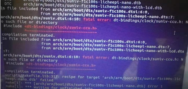
设备树文件编译不过去,查资料应该是头文件路径的问题,要建一个软连接到include/dt-bindings下,回头试一下。
目前先把lcd点亮,这样信心也足一点,所以问一下,我能不能用我修改的这个设备树文件编译生成dtb,替换掉荔枝派NANO资料包里打包好的TF卡的烧录文件中的dtb文件,通过TF卡启动从而点亮LCD?就是不知道荔枝派的内核文件里有没有把SPI-TFT驱动添加进去?
没找到如何上传pdf文件方法,先传上原理图的截图吧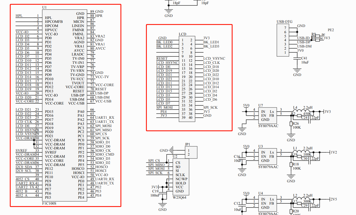
#17 Re: 全志 SOC » 发现淘宝有卖F1C100S源码的 » 2019-10-12 11:27:33
#18 Re: 好钜润半导体(TIKY) » 好钜润半导体 4.3寸液晶屏, TKM32F499 » 2019-10-09 09:29:48
晕哥 wrote:
/files/members/3/2019-09-17_223542.png
全志soc, 比如V3s, f1c100s 支持 RGB I/F 驱动接口, 但是需要用SPI/I2C初始化.
当然也支持 I80 接口.
晕哥像这样的SPI+RGB的液晶屏,f1c100s有相应的驱动配置吗,不知道SPI初始化的设备树如何配置
页次: 1
- 首页
- » 搜索
- » xbgzy 发表的帖子
东莞哇酷科技有限公司开发