- 首页
- » 搜索
- » Simn 发表的帖子
页次: 1
#1 Re: 全志 SOC » F1C200S SPI->ST7789 » 2023-02-28 01:41:52
#2 Re: 全志 SOC » F1C200S SPI->ST7789 » 2023-02-26 00:58:52
#3 Re: 全志 SOC » F1C200S SPI->ST7789 » 2023-02-24 23:33:26
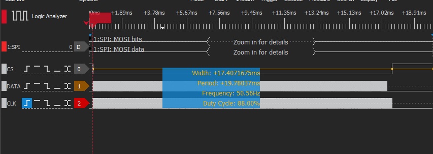
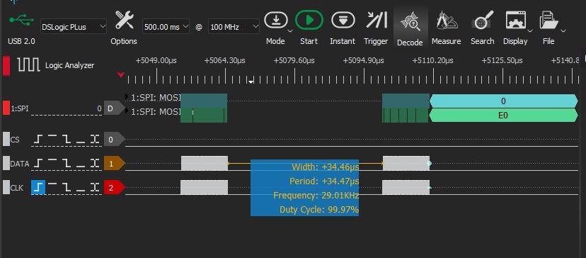
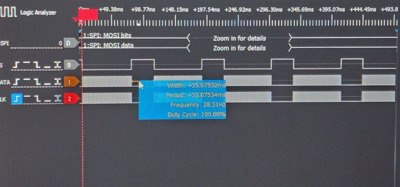
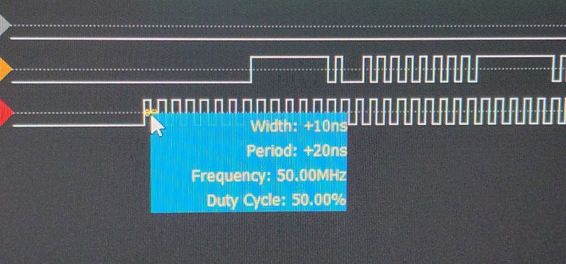
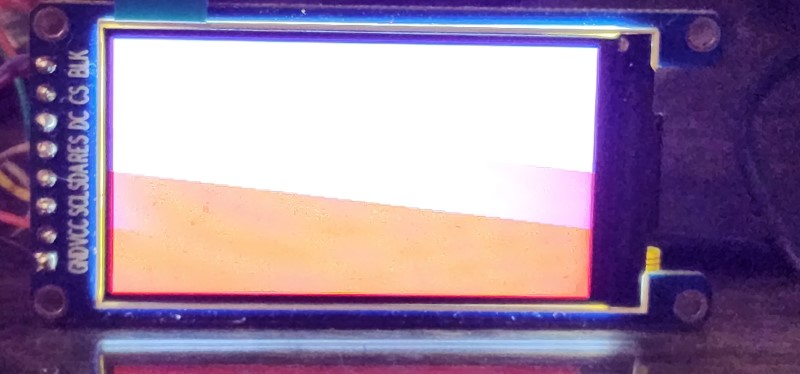
配置 DMA SPI 再次出现问题。 发送前 64 个字节,然后挂起 while(NDMA0->CR & NDMA_CFG_BUSY_STATUS)SPI1_RXD_BYTE;问题是什么?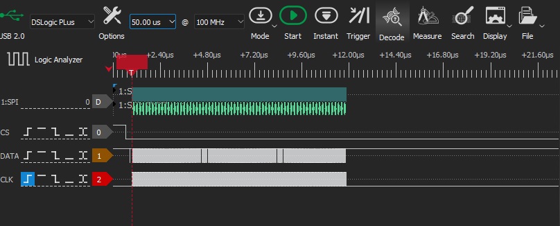
https://whycan.com/t_3405.html
NDMA0->CR = NDMA_CFG_DRQ_SPI1_TX      |
                NDMA_CFG_DRQ_SDRAM_MEMORY |
                NDMA_CFG_ADDRESS_IO_MODE  |
                NDMA_CFG_WAIT_STATE2;
    NDMA0->SAR =&disp_buf;
    NDMA0->DAR = SPI1_TXD_BYTE;

    *SPI1_FCR = SPI_FCR_RF_RST         |
                SPI_FCR_TX_FIFO_RST    |
                SPI_FCR_TF_DRQ_EN      |
                SPI_FCR_TX_TRIG_LEV_64 |
                SPI_FCR_RX_FIFO_RST    |
                SPI_FCR_RX_TRIG_LEV_1;
void flushDMA()
{
*SPI1_MBC = *SPI1_MTC = *SPI1_BCC = NDMA0->BCR = 170*320*2;
NDMA0->CR |=NDMA_CFG_LOADING;
*SPI1_TCR &= ~SPI_TCR_SS_LEVEL_HIGH;
*SPI1_TCR |= SPI_TCR_XCH_START;
while(NDMA0->CR & NDMA_CFG_BUSY_STATUS) SPI1_RXD_BYTE;
*SPI1_ISR |= SPI_ISR_TC;
while(!(*SPI1_ISR&SPI_ISR_TC)SPI1_RXD_BYTE;
*SPI1_TCR |= SPI_TCR_SS_LEVEL_HIGH;
}#4 Re: 全志 SOC » F1C200S SPI->ST7789 » 2023-02-20 02:47:41
#5 Re: 全志 SOC » F1C200S SPI->ST7789 » 2023-02-18 15:43:15
代码贴出来看看 啊
void spi_write(unsigned char *buffer, int length)
{
  int i;
  int cnt;

  while(length)
  {

    if(length <= 64)
      cnt = length;
    else
      cnt = 64;
    //number of bytes burst
    *SPI0_MBC = cnt;
    //number of bytes to transmit
    *SPI0_MTC = cnt;
    *SPI0_BCC = cnt;
    //Load FIFO
    for(i=0;i<cnt;++i)
      *SPI0_TXD_BYTE = *buffer++;
    //Start
    *SPI0_TCR |= SPI_TCR_XCH_START;
    length -= cnt;
    while(*SPI0_TCR & SPI_TCR_XCH_START);
    *SPI0_FCR |= SPI_FCR_RX_FIFO_RST;
    while(*SPI0_FCR & SPI_FCR_RX_FIFO_RST);
  }
}
void LCD_Fill(uint16_t Color)
{
uint16_t i, j;
for (i = 0; i < LCD_WIDTH; i++)
for (j = 0; j < LCD_HEIGHT; j++)
{
*(volatile uint16_t *) (disp_buf + j * LCD_WIDTH + i) = Color;
}
SetAddressWindow(0, 0, LCD_WIDTH - 1, LCD_HEIGHT - 1);
spi_write(disp_buf,LCD_WIDTH * LCD_HEIGHT*2);
}#8 全志 SOC » 在SPL Boot f1c200s FatFs 不能正常工作是什么原因? » 2023-01-19 00:05:23
- Simn
- 回复: 1
大家好! 在 FatFs 方面需要帮助。 面对一个难以理解的问题,相同的代码表现不同,SDC 和 FatFs 可以正常工作 如果你编译二进制文件并在 DDR 中运行
xfel ddr F1C200S
xfel write 0x80000000 f1c200s.bin
xfel exec 0x80000000
但是如果 FatFs 为 spl 引导编译
sunxi-fel -v -p spl boot.bin
uint8_t state = f_mount(&fs, "", 1); // return FR_NO_FILESYSTEM, /* (13) There is no valid FAT volume */
state = f_open(&imgfile, "image.bin", FA_READ); // return FR_NO_FILESYSTEM, /* (13) There is no valid FAT volume */
在SPL Boot f1c200s FatFs 不能正常工作是什么原因?
#9 Re: 全志 SOC » 使用 SOC F1Cxxx 的多媒体设备精选 » 2023-01-12 21:09:39
#10 Re: 全志 SOC » 使用 SOC F1Cxxx 的多媒体设备精选 » 2023-01-11 21:44:26
#11 Re: 全志 SOC » F1C100S + FreeRTOS + USB Host » 2023-01-11 07:52:41
#12 Re: 全志 SOC » 使用 SOC F1Cxxx 的多媒体设备精选 » 2023-01-09 19:35:06
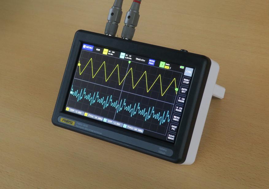
大彩的串口屏也是用F1C100S ?
是的。屏幕有几种选择 DWIN,SYNWIT,F1C100S...
https://github.com/mriscoc/Ender3V2S1/wiki/How-to-update-the-display
#13 Re: 全志 SOC » 使用 SOC F1Cxxx 的多媒体设备精选 » 2023-01-07 01:27:28
#14 Re: 全志 SOC » F1C100S/F1C200S如何进入休眠模式 » 2023-01-06 05:50:30
mcr 指令 p15, 0, r0, c7, c0, 4 /* 等待中断 */
我对 DOZE/SLEEP mode 模式感兴趣 https://developer.arm.com/documentation/ddi0287/b/introduction-and-configuration/system-controller-and-configuration-logic/about-the-system-controller/system-mode-control?lang=en
ARM926EJ-S Development Chip Reference Manual
"SLEEP mode
In SLEEP mode, the system clocks, HCLK and CLK, are disabled and the System Controller clock, SCLK, is driven from a slow speed oscillator (nominally 32 768Hz).
When either a FIQ or an IRQ interrupt is activated (through the VIC) the system moves into the DOZE mode. Additionally, the required operating mode in the system control register automatically changes from SLEEP to DOZE.
Note
Before entering SLEEP mode you must ensure that the processor is in the Wait-for-interrupt state. Processor status is determined by the STANDBYWFI output from the processor.
DOZE mode
In DOZE mode, the system clocks and the System Controller clock are driven from a low frequency oscillator.
From DOZE mode it is possible to move into SLEEP mode when none of the mode control bits are set and the processor is in Wait-for-interrupt state.
If SLOW mode or NORMAL mode is required the system moves into the XTAL control transition state to initialize the crystal oscillator."
#15 Re: 全志 SOC » 使用 SOC F1Cxxx 的多媒体设备精选 » 2023-01-06 04:22:50
#17 Re: 全志 SOC » 新作F1C200S,打算百分之百开源,给大家的新年礼物。 » 2023-01-05 06:10:38
#18 Re: 全志 SOC » 使用 SOC F1Cxxx 的多媒体设备精选 » 2022-12-23 03:32:12
#19 Re: 全志 SOC » f1c100s入门 » 2022-12-14 16:42:44
这里有个f1c100s+FreeRTOS的例程,可直接debug运行的,支持LCD,串口打印之类的,可以一起学习
https://download.csdn.net/download/chenbee168/86988791
以及如何下载? csdn:(((
#20 Re: 全志 SOC » F1C100S FreeRTOS工程,100%可用 » 2022-12-14 16:40:54
#21 Re: 全志 SOC » 使用 SOC F1Cxxx 的多媒体设备精选 » 2022-12-14 02:05:19
#22 Re: 全志 SOC » 使用 SOC F1Cxxx 的多媒体设备精选 » 2022-12-14 01:31:26
#23 Re: 全志 SOC » 使用 SOC F1Cxxx 的多媒体设备精选 » 2022-12-14 01:21:18
#25 Re: 全志 SOC » F1C100s UART寄存器 » 2022-11-28 05:26:18
大概知道了,根据不同的标志位访问权限不同
Ofset 0x00 Read RBR ( data bit 7:0) bits 7:0
Ofset 0x00 Write THR ( data bit 7:0) bits 7:0
Ofset 0x00 R/W DLL ( data bit 7:0) bits 15:8 Divisor Latch low (7:0 Read RBR / Write THR)
Exemple:
uint16_t val = (uint16_t)(apb_clock / baud / 16UL);
write32(UartBase+DLL, val & 0xFF); // Write divisor value
inline void uart_tx(uint32_t UartBase, uint8_t data)
{
write32(UartBase+THR, data);
}
inline uint8_t uart_get_rx(uint32_t UartBase)
{
return (uint8_t)read32(UartBase+RBR);
}
#26 Re: 全志 SOC » F1C100S的Keil裸机USB+LCD+PWM+GPIO工程搞定,修复GNU工具链BUG » 2022-11-28 00:58:48
@右半边天天晴
asm volatile (
"b Entry \n" //Jump to Entry
".long 0x4E4F4765\n" //eGON
".long 0x3054422E\n" //.BT0
".long 0x00000000\n" //checksum for boot must be calculated !
".long 0x00006000\n" //length for boot 0x6000 24 kB
".long 0x00000000\n"
".long 0x00000000\n"
".long 0x00000000\n"
);
or
_start:
//Boot head information for BROM
.long 0xea000006 //Jump to Entry
.byte 'e', 'G', 'O', 'N', '.', 'E', 'X', 'E'
.long 0, __program_size //checksum for boot must be calculated !, length for boot
.byte 'E', 'X', 'E', 'C' //
.long 0, 0
or
;/* Boot head information for BROM booting */
BROM_BHI B Vectors
DCB "eGON.BT0"
DCD 0, ||Load$$LR$$FLASH_SPL$$Length||
DCB 'S', 'P', 'L', 2
DCD 0, 0
DCD 0, 0, 0, 0, 0, 0, 0, 0
;/* 0x40 - boot params, 0x54 - entry, 0x58 - fel boot type, 0x5c - dram size */
DCD 0, 0, 0, 0, 0, 0, 0, 0
#27 Re: 全志 SOC » Windows裸机程序烧录工具,烧录到SD卡 » 2022-11-25 02:36:17
我使用 cfimager.exe + *.BAT 实用程 但是你的实用程序更有趣
cfimager.exe tool is used to flash boot images and create FAT partition on SD/MMC cards
on the host PC
- To flash the uboot, use the following command:
cfimager -raw -offset 0x400 -skip 0x400 -f u-boot.bin -d
cfimager.exe -raw -offset 0x2000 -f boot.bin -d F
Note if changing -offset 0xXXXX, other image can be flashed to SD card "F".
Exemple bat file:
rem cfimager.exe -raw -offset 0x2000 -f boot.bin -d Disk F
cfimager.exe -raw -offset 0x2000 -f boot.bin -d F
pause
https://gitlab.com/my-imx6/mfgtools/tree/master/Utils/cfimager
https://github.com/NXPmicro/cfimager
#28 Re: Nuvoton N32905/N32926/NUC972/N9H20/N9H26/N9H30 » step by step 全志 f1c100s MDK 裸奔各种外设(参考N3290x) » 2022-11-25 00:09:43
https://whycan.cn/files/members/713/QQ20180821093222.jpg
紧跟楼主步伐,学习 f1c100s mdk 裸奔.
jlink 可以连上,mdk 可以调试。
J-link适配器原件还是复印件? 哪个版本? 我在哪里可以买到?
#29 Re: 计算机图形/GUI/RTOS/FileSystem/OpenGL/DirectX/SDL2 » LingLongGUI是是高效的界面开发解决方案。 » 2022-11-22 22:36:07
#31 Re: 全志 SOC » 开源一个F1C200S的实用向板,极限压榨这片子的功能 » 2022-11-21 21:41:28
#32 Re: 全志 SOC » 搞定 T113 / T113-S3 裸奔驱动CAN (转) » 2022-11-21 21:09:24
#33 Re: 全志 SOC » 开源一个F1C200S的实用向板,极限压榨这片子的功能 » 2022-11-19 19:45:27
页次: 1
- 首页
- » 搜索
- » Simn 发表的帖子
太原小智科技有限责任公司 - 东莞哇酷科技有限公司联合开发
