楼主 #1 2018-05-28 10:31:24 分享评论
楼主 #2 2018-05-28 11:46:00 分享评论
- 晕哥
- 管理员
- 所在地: wechat: whycan_cn
- 注册时间: 2017-09-06
- 已发帖子: 9,433
- 积分: 9202
Re: 测试 物联网俱乐部 STM32L431RCT6开发板外设
MDK 5.25下载: https://armkeil.blob.core.windows.net/eval/MDK525.EXE
据说 MDK 一个最重大的更新 V5.25版本, 下载下来试一试.
Keil pack@STM32L4xx: Keil.STM32L4xx_DFP.2.0.0.pack
ST官方SDK开发包V1.11.0下载: en.stm32cubel4.zip
STM32L4xx应用手册: en.DM00151940.pdf
STM32L431xx芯片手册: en.DM00257211.pdf
STM32L4超低功耗功能概述: zh.DM00148033.pdf
离线
楼主 #3 2018-05-28 14:48:45 分享评论
楼主 #4 2018-05-28 15:19:28 分享评论
- 晕哥
- 管理员
- 所在地: wechat: whycan_cn
- 注册时间: 2017-09-06
- 已发帖子: 9,433
- 积分: 9202
Re: 测试 物联网俱乐部 STM32L431RCT6开发板外设
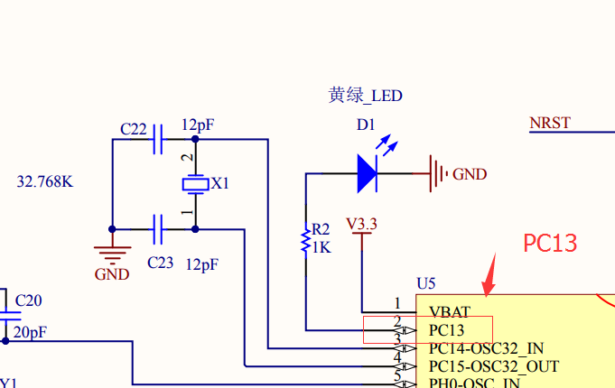
工程路径: STM32Cube_FW_L4_V1.11.0\Projects\NUCLEO-L432KC\Examples\GPIO\GPIO_IOToggle\MDK-ARM\Project.uvprojx
修改 stm32l4xx_nucleo_32.h:
#define LED3_PIN                           GPIO_PIN_13
#define LED3_GPIO_PORT                     GPIOC
#define LED3_GPIO_CLK_ENABLE()             __HAL_RCC_GPIOC_CLK_ENABLE()
#define LED3_GPIO_CLK_DISABLE()            __HAL_RCC_GPIOC_CLK_DISABLE()
可以点亮板子上的LED PC13
离线
楼主 #5 2018-05-28 16:51:28 分享评论
- 晕哥
- 管理员
- 所在地: wechat: whycan_cn
- 注册时间: 2017-09-06
- 已发帖子: 9,433
- 积分: 9202
Re: 测试 物联网俱乐部 STM32L431RCT6开发板外设
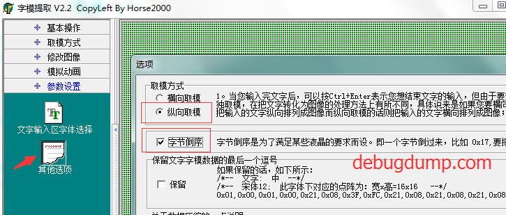
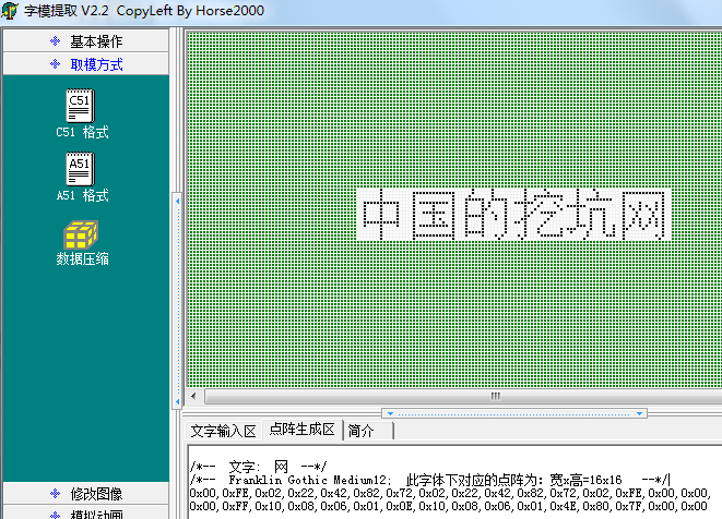
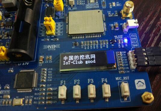
char Hzk[][32]={
/*--  文字:  中  --*/
/*--  Franklin Gothic Medium12;  此字体下对应的点阵为:宽x高=16x16   --*/
{0x00,0x00,0xF0,0x10,0x10,0x10,0x10,0xFF,0x10,0x10,0x10,0x10,0xF0,0x00,0x00,0x00,},
{0x00,0x00,0x0F,0x04,0x04,0x04,0x04,0xFF,0x04,0x04,0x04,0x04,0x0F,0x00,0x00,0x00},

/*--  文字:  国  --*/
/*--  Franklin Gothic Medium12;  此字体下对应的点阵为:宽x高=16x16   --*/
{0x00,0xFE,0x02,0x12,0x92,0x92,0x92,0xF2,0x92,0x92,0x92,0x12,0x02,0xFE,0x00,0x00,},
{0x00,0xFF,0x40,0x48,0x48,0x48,0x48,0x4F,0x48,0x4A,0x4C,0x48,0x40,0xFF,0x00,0x00},

/*--  文字:  的  --*/
/*--  Franklin Gothic Medium12;  此字体下对应的点阵为:宽x高=16x16   --*/
{0x00,0xF8,0x0C,0x0B,0x08,0x08,0xF8,0x40,0x30,0x8F,0x08,0x08,0x08,0xF8,0x00,0x00,},
{0x00,0x7F,0x21,0x21,0x21,0x21,0x7F,0x00,0x00,0x00,0x43,0x80,0x40,0x3F,0x00,0x00},

/*--  文字:  挖  --*/
/*--  Franklin Gothic Medium12;  此字体下对应的点阵为:宽x高=16x16   --*/
{0x10,0x10,0x10,0xFF,0x10,0x90,0x4C,0x24,0x94,0x85,0x86,0x84,0x94,0x24,0x4C,0x00,},
{0x04,0x44,0x82,0x7F,0x01,0x00,0x00,0x30,0x48,0x44,0x42,0x41,0x40,0x40,0x70,0x00},

/*--  文字:  坑  --*/
/*--  Franklin Gothic Medium12;  此字体下对应的点阵为:宽x高=16x16   --*/
{0x20,0x20,0x20,0xFF,0x20,0x20,0x08,0xC8,0x49,0x4E,0x48,0xC8,0x08,0x08,0x00,0x00,},
{0x10,0x30,0x10,0x0F,0x08,0x88,0x60,0x1F,0x00,0x00,0x00,0x3F,0x40,0x40,0x78,0x00},

/*--  文字:  网  --*/
/*--  Franklin Gothic Medium12;  此字体下对应的点阵为:宽x高=16x16   --*/
{0x00,0xFE,0x02,0x22,0x42,0x82,0x72,0x02,0x22,0x42,0x82,0x72,0x02,0xFE,0x00,0x00,},
{0x00,0xFF,0x10,0x08,0x06,0x01,0x0E,0x10,0x08,0x06,0x01,0x4E,0x80,0x7F,0x00,0x00},
}
参考网址: https://whycan.cn/t_982.html
字模软件: zimoV2_2.rar
离线
楼主 #6 2018-05-28 17:48:43 分享评论
- 晕哥
- 管理员
- 所在地: wechat: whycan_cn
- 注册时间: 2017-09-06
- 已发帖子: 9,433
- 积分: 9202
Re: 测试 物联网俱乐部 STM32L431RCT6开发板外设
直接使用HAL库驱动 物联网俱乐部开发板 OLED液晶屏
下载地址: OLED.7z
解压位置: STM32Cube_FW_L4_V1.11.0\Projects\NUCLEO-L432KC\Examples
使用MDK5.xx 打开工程文件: STM32Cube_FW_L4_V1.11.0\Projects\NUCLEO-L432KC\Examples\OLED\GPIO_IOToggle\MDK-ARM\Project.uvprojx
离线
楼主 #7 2018-05-28 22:26:29 分享评论
- 晕哥
- 管理员
- 所在地: wechat: whycan_cn
- 注册时间: 2017-09-06
- 已发帖子: 9,433
- 积分: 9202
Re: 测试 物联网俱乐部 STM32L431RCT6开发板外设
搞定一个低功耗应用 STM32Cube_FW_L4_V1.11.0\Projects\NUCLEO-L432KC\Examples\PWR\PWR_LPRUN\MDK-ARM\Project.uvprojx
main.c
/**
******************************************************************************
* @file PWR/PWR_LPRUN/Src/main.c
* @author MCD Application Team
* @brief This sample code shows how to use STM32L4xx PWR HAL API to enter
* and exit the Low Power Run mode.
******************************************************************************
* @attention
*
* <h2><center>© COPYRIGHT(c) 2017 STMicroelectronics</center></h2>
*
* Redistribution and use in source and binary forms, with or without modification,
* are permitted provided that the following conditions are met:
* 1. Redistributions of source code must retain the above copyright notice,
* this list of conditions and the following disclaimer.
* 2. Redistributions in binary form must reproduce the above copyright notice,
* this list of conditions and the following disclaimer in the documentation
* and/or other materials provided with the distribution.
* 3. Neither the name of STMicroelectronics nor the names of its contributors
* may be used to endorse or promote products derived from this software
* without specific prior written permission.
*
* THIS SOFTWARE IS PROVIDED BY THE COPYRIGHT HOLDERS AND CONTRIBUTORS "AS IS"
* AND ANY EXPRESS OR IMPLIED WARRANTIES, INCLUDING, BUT NOT LIMITED TO, THE
* IMPLIED WARRANTIES OF MERCHANTABILITY AND FITNESS FOR A PARTICULAR PURPOSE ARE
* DISCLAIMED. IN NO EVENT SHALL THE COPYRIGHT HOLDER OR CONTRIBUTORS BE LIABLE
* FOR ANY DIRECT, INDIRECT, INCIDENTAL, SPECIAL, EXEMPLARY, OR CONSEQUENTIAL
* DAMAGES (INCLUDING, BUT NOT LIMITED TO, PROCUREMENT OF SUBSTITUTE GOODS OR
* SERVICES; LOSS OF USE, DATA, OR PROFITS; OR BUSINESS INTERRUPTION) HOWEVER
* CAUSED AND ON ANY THEORY OF LIABILITY, WHETHER IN CONTRACT, STRICT LIABILITY,
* OR TORT (INCLUDING NEGLIGENCE OR OTHERWISE) ARISING IN ANY WAY OUT OF THE USE
* OF THIS SOFTWARE, EVEN IF ADVISED OF THE POSSIBILITY OF SUCH DAMAGE.
*
******************************************************************************
*/
/* Includes ------------------------------------------------------------------*/
#include "main.h"
/** @addtogroup STM32L4xx_HAL_Examples
* @{
*/
/** @addtogroup PWR_LPRUN
* @{
*/
/* Private typedef -----------------------------------------------------------*/
/* Private define ------------------------------------------------------------*/
#define LED_TOGGLE_DELAY 100
/* Private macro -------------------------------------------------------------*/
/* Private variables ---------------------------------------------------------*/
static __IO uint32_t TimingDelay;
/* Private function prototypes -----------------------------------------------*/
void SystemClock_Config(void);
static void SystemPower_Config(void);
void SystemClock_Decrease(void);
/* Private functions ---------------------------------------------------------*/
/**
* @brief Main program
* @param None
* @retval None
*/
int main(void)
{
GPIO_InitTypeDef GPIO_InitStruct;
/* STM32L4xx HAL library initialization:
- Configure the Flash prefetch
- Systick timer is configured by default as source of time base, but user
can eventually implement his proper time base source (a general purpose
timer for example or other time source), keeping in mind that Time base
duration should be kept 1ms since PPP_TIMEOUT_VALUEs are defined and
handled in milliseconds basis.
- Set NVIC Group Priority to 4
- Low Level Initialization
*/
HAL_Init();
/* Configure the system clock for the RUN mode */
SystemClock_Config();
/* Configure LED3 */
BSP_LED_Init(LED3);
/* Disable Prefetch Buffer */
/* (uncomment this line if power consumption figures */
/* must be measured with Adaptive Real Time (ART) */
/* memory accelerator on) */
__HAL_FLASH_PREFETCH_BUFFER_DISABLE();
while (1)
{
/* Insert 5 seconds delay */
HAL_Delay(5000);
/* Configure the system Power */
SystemPower_Config();
/* PA.12 (Arduino D2) will be used to exit from Low Power Run mode */
GPIO_InitStruct.Pin = GPIO_PIN_0;
GPIO_InitStruct.Pull = GPIO_PULLUP;
GPIO_InitStruct.Mode = GPIO_MODE_INPUT;
GPIO_InitStruct.Speed = GPIO_SPEED_FREQ_VERY_HIGH;
/* Enable GPIOC clock */
__HAL_RCC_GPIOC_CLK_ENABLE();
HAL_GPIO_Init(GPIOC, &GPIO_InitStruct);
/* Reduce the System clock to below 2 MHz */
SystemClock_Decrease();
/* Suspend Tick increment for power consumption purposes */
HAL_SuspendTick();
/* Enter LP RUN Mode */
HAL_PWREx_EnableLowPowerRunMode();
/* Wait until jumper is put between PA.12 (Arduino D2) and GND */
while(HAL_GPIO_ReadPin(GPIOC, GPIO_PIN_0) == GPIO_PIN_RESET)
{
}
/* Wait until jumper is removed */
while(HAL_GPIO_ReadPin(GPIOC, GPIO_PIN_0) == GPIO_PIN_SET)
{
}
/* System is Low Power Run mode when exiting Low Power Sleep mode,
disable low power run mode and reset the clock to initialization configuration */
HAL_PWREx_DisableLowPowerRunMode();
SystemClock_Config();
/* Re-init LED3 to toggle during Run mode */
BSP_LED_Init(LED3);
/* Resume Tick interrupt if disabled prior to Low Power Run mode entry */
HAL_ResumeTick();
}
}
/**
* @brief System Clock Configuration
* The system Clock is configured as follow :
* System Clock source = HSI
* SYSCLK(Hz) = 32,000,0000
* AHB Prescaler = 1
* APB1 Prescaler = 1
* APB2 Prescaler = 1
* MSI Frequency(Hz) = 4,000,000
* HSI Frequency(Hz) = 16,000,000
* Flash Latency(WS) = 1
* @param None
* @retval None
*/
void SystemClock_Config(void)
{
RCC_ClkInitTypeDef RCC_ClkInitStruct = {0};
RCC_OscInitTypeDef RCC_OscInitStruct = {0};
HAL_RCC_DeInit();
/* MSI is enabled after System reset, configure HSI */
RCC_OscInitStruct.OscillatorType = RCC_OSCILLATORTYPE_HSI;
RCC_OscInitStruct.HSIState = RCC_HSI_ON;
RCC_OscInitStruct.HSICalibrationValue = RCC_HSICALIBRATION_DEFAULT;
RCC_OscInitStruct.PLL.PLLState = RCC_PLL_NONE;
if(HAL_RCC_OscConfig(&RCC_OscInitStruct) != HAL_OK)
{
/* Initialization Error */
while(1);
}
/* Select HSI as system clock source and configure the HCLK, PCLK1 and PCLK2
clocks dividers */
RCC_ClkInitStruct.ClockType = RCC_CLOCKTYPE_SYSCLK;
RCC_ClkInitStruct.SYSCLKSource = RCC_SYSCLKSOURCE_HSI;
RCC_ClkInitStruct.AHBCLKDivider = RCC_SYSCLK_DIV1;
RCC_ClkInitStruct.APB1CLKDivider = RCC_HCLK_DIV1;
RCC_ClkInitStruct.APB2CLKDivider = RCC_HCLK_DIV1;
if(HAL_RCC_ClockConfig(&RCC_ClkInitStruct, FLASH_LATENCY_1) != HAL_OK)
{
/* Initialization Error */
while(1);
}
}
/**
* @brief System Power Configuration
* The system Power is configured as follow :
* + System Running at MSI Range 0 (~100 KHz)
* + Flash 0 wait state
* + Voltage Range 2
* + Code running from Internal FLASH
+ Exit from LP Run mode using PA.12 (Arduino D2)
* @param None
* @retval None
*/
static void SystemPower_Config(void)
{
GPIO_InitTypeDef GPIO_InitStructure;
/* Enable Power Clock */
__HAL_RCC_PWR_CLK_ENABLE();
/* Enable GPIOs clock */
__HAL_RCC_GPIOA_CLK_ENABLE();
__HAL_RCC_GPIOB_CLK_ENABLE();
__HAL_RCC_GPIOC_CLK_ENABLE();
__HAL_RCC_GPIOH_CLK_ENABLE();
/* Configure all GPIO port pins in Analog Input mode (floating input trigger OFF) */
/* Note: Debug using ST-Link is not possible during the execution of this */
/* example because communication between ST-link and the device */
/* under test is done through UART. All GPIO pins are disabled (set */
/* to analog input mode) including UART I/O pins. */
GPIO_InitStructure.Pin = GPIO_PIN_All;
GPIO_InitStructure.Mode = GPIO_MODE_ANALOG;
GPIO_InitStructure.Pull = GPIO_NOPULL;
HAL_GPIO_Init(GPIOA, &GPIO_InitStructure);
HAL_GPIO_Init(GPIOB, &GPIO_InitStructure);
HAL_GPIO_Init(GPIOC, &GPIO_InitStructure);
HAL_GPIO_Init(GPIOH, &GPIO_InitStructure);
/* Disable GPIOs clock */
__HAL_RCC_GPIOA_CLK_DISABLE();
__HAL_RCC_GPIOB_CLK_DISABLE();
__HAL_RCC_GPIOC_CLK_DISABLE();
__HAL_RCC_GPIOH_CLK_DISABLE();
}
/**
* @brief System Clock Speed decrease
* The system Clock source is shifted from HSI to MSI
* while at the same time, MSI range is set to RCC_MSIRANGE_0
* to go down to 100 KHz
* @param None
* @retval None
*/
void SystemClock_Decrease(void)
{
RCC_ClkInitTypeDef RCC_ClkInitStruct = {0};
RCC_OscInitTypeDef RCC_OscInitStruct = {0};
/* MSI is enabled after System reset, activate PLL with MSI as source */
RCC_OscInitStruct.OscillatorType = RCC_OSCILLATORTYPE_MSI;
RCC_OscInitStruct.MSIState = RCC_MSI_ON;
RCC_OscInitStruct.MSIClockRange = RCC_MSIRANGE_0;
RCC_OscInitStruct.MSICalibrationValue = RCC_MSICALIBRATION_DEFAULT;
RCC_OscInitStruct.PLL.PLLState = RCC_PLL_NONE;
if(HAL_RCC_OscConfig(&RCC_OscInitStruct) != HAL_OK)
{
/* Initialization Error */
while(1);
}
/* Select MSI as system clock source and configure the HCLK, PCLK1 and PCLK2
clocks dividers */
RCC_ClkInitStruct.ClockType = RCC_CLOCKTYPE_SYSCLK;
RCC_ClkInitStruct.SYSCLKSource = RCC_SYSCLKSOURCE_MSI;
RCC_ClkInitStruct.AHBCLKDivider = RCC_SYSCLK_DIV1;
RCC_ClkInitStruct.APB1CLKDivider = RCC_HCLK_DIV1;
RCC_ClkInitStruct.APB2CLKDivider = RCC_HCLK_DIV1;
if(HAL_RCC_ClockConfig(&RCC_ClkInitStruct, FLASH_LATENCY_0) != HAL_OK)
{
/* Initialization Error */
while(1);
}
/* Disable HSI to reduce power consumption since MSI is used from that point */
__HAL_RCC_HSI_DISABLE();
}
/**
* @brief SYSTICK callback
* @param None
* @retval None
*/
void HAL_SYSTICK_Callback(void)
{
HAL_IncTick();
if (TimingDelay != 0)
{
TimingDelay--;
}
else
{
/* Toggle LED3 */
BSP_LED_Toggle(LED3);
TimingDelay = LED_TOGGLE_DELAY;
}
}
#ifdef USE_FULL_ASSERT
/**
* @brief Reports the name of the source file and the source line number
* where the assert_param error has occurred.
* @param file: pointer to the source file name
* @param line: assert_param error line source number
* @retval None
*/
void assert_failed(char *file, uint32_t line)
{
/* User can add his own implementation to report the file name and line number,
ex: printf("Wrong parameters value: file %s on line %d\r\n", file, line) */
/* Infinite loop */
while (1)
{
}
}
#endif
/**
* @}
*/
/**
* @}
*/
/************************ (C) COPYRIGHT STMicroelectronics *****END OF FILE****/stm32l4xx_nucleo_32.h
/**
******************************************************************************
* @file stm32l4xx_nucleo_32.h
* @author MCD Application Team
* @version V1.0.0
* @date 26-February-2016
* @brief This file contains definitions for:
* - LED available on STM32L4xx-Nucleo_32 Kit from STMicroelectronics
* - 7 segment display from Gravitech
******************************************************************************
* @attention
*
* <h2><center>© COPYRIGHT(c) 2016 STMicroelectronics</center></h2>
*
* Redistribution and use in source and binary forms, with or without modification,
* are permitted provided that the following conditions are met:
* 1. Redistributions of source code must retain the above copyright notice,
* this list of conditions and the following disclaimer.
* 2. Redistributions in binary form must reproduce the above copyright notice,
* this list of conditions and the following disclaimer in the documentation
* and/or other materials provided with the distribution.
* 3. Neither the name of STMicroelectronics nor the names of its contributors
* may be used to endorse or promote products derived from this software
* without specific prior written permission.
*
* THIS SOFTWARE IS PROVIDED BY THE COPYRIGHT HOLDERS AND CONTRIBUTORS "AS IS"
* AND ANY EXPRESS OR IMPLIED WARRANTIES, INCLUDING, BUT NOT LIMITED TO, THE
* IMPLIED WARRANTIES OF MERCHANTABILITY AND FITNESS FOR A PARTICULAR PURPOSE ARE
* DISCLAIMED. IN NO EVENT SHALL THE COPYRIGHT HOLDER OR CONTRIBUTORS BE LIABLE
* FOR ANY DIRECT, INDIRECT, INCIDENTAL, SPECIAL, EXEMPLARY, OR CONSEQUENTIAL
* DAMAGES (INCLUDING, BUT NOT LIMITED TO, PROCUREMENT OF SUBSTITUTE GOODS OR
* SERVICES; LOSS OF USE, DATA, OR PROFITS; OR BUSINESS INTERRUPTION) HOWEVER
* CAUSED AND ON ANY THEORY OF LIABILITY, WHETHER IN CONTRACT, STRICT LIABILITY,
* OR TORT (INCLUDING NEGLIGENCE OR OTHERWISE) ARISING IN ANY WAY OUT OF THE USE
* OF THIS SOFTWARE, EVEN IF ADVISED OF THE POSSIBILITY OF SUCH DAMAGE.
*
******************************************************************************
*/
/* Define to prevent recursive inclusion -------------------------------------*/
#ifndef __STM32L4XX_NUCLEO_32_H
#define __STM32L4XX_NUCLEO_32_H
#ifdef __cplusplus
extern "C" {
#endif
/* Includes ------------------------------------------------------------------*/
#include "stm32l4xx_hal.h"
/** @addtogroup BSP
* @{
*/
/** @defgroup STM32L4XX_NUCLEO_32 NUCLEO 32
* @brief This section contains the exported types, contants and functions
* required to use the Nucleo 32 board.
* @{
*/
/** @defgroup STM32L4XX_NUCLEO_32_Exported_Types Exported Types
* @{
*/
typedef enum
{
LED3 = 0,
LED_GREEN = LED3
} Led_TypeDef;
/**
* @}
*/
/** @defgroup STM32L4XX_NUCLEO_32_Exported_Constants Exported Constants
* @brief Define for STM32L4XX_NUCLEO_32 board
* @{
*/
#if !defined (USE_STM32L4XX_NUCLEO_32)
#define USE_STM32L4XX_NUCLEO_32
#endif
/** @defgroup STM32L4XX_NUCLEO_LED LED Constants
* @{
*/
#define LEDn 1
#define LED3_PIN GPIO_PIN_13
#define LED3_GPIO_PORT GPIOC
#define LED3_GPIO_CLK_ENABLE() __HAL_RCC_GPIOC_CLK_ENABLE()
#define LED3_GPIO_CLK_DISABLE() __HAL_RCC_GPIOC_CLK_DISABLE()
#define LEDx_GPIO_CLK_ENABLE(__INDEX__) do {LED3_GPIO_CLK_ENABLE(); } while(0)
#define LEDx_GPIO_CLK_DISABLE(__INDEX__) LED3_GPIO_CLK_DISABLE())
/**
* @}
*/
/** @defgroup STM32L4XX_NUCLEO_32_BUS BUS Constants
* @{
*/
#if defined(HAL_I2C_MODULE_ENABLED)
/*##################### I2C1 ###################################*/
/* User can use this section to tailor I2Cx instance used and associated resources */
/* Definition for I2C1 Pins */
#define BSP_I2C1 I2C1
#define BSP_I2C1_CLK_ENABLE() __HAL_RCC_I2C1_CLK_ENABLE()
#define BSP_I2C1_CLK_DISABLE() __HAL_RCC_I2C1_CLK_DISABLE()
#define BSP_I2C1_FORCE_RESET() __HAL_RCC_I2C1_FORCE_RESET()
#define BSP_I2C1_RELEASE_RESET() __HAL_RCC_I2C1_RELEASE_RESET()
#define BSP_I2C1_SCL_PIN GPIO_PIN_6 /* PB.6 add wire between D5 and A5 */
#define BSP_I2C1_SDA_PIN GPIO_PIN_7 /* PB.7 add wire between D4 and A4 */
#define BSP_I2C1_GPIO_PORT GPIOB /* GPIOB */
#define BSP_I2C1_GPIO_CLK_ENABLE() __HAL_RCC_GPIOB_CLK_ENABLE()
#define BSP_I2C1_GPIO_CLK_DISABLE() __HAL_RCC_GPIOB_CLK_DISABLE()
#define BSP_I2C1_SCL_SDA_AF GPIO_AF4_I2C1
/* Maximum Timeout values for flags waiting loops. These timeouts are not based
on accurate values, they just guarantee that the application will not remain
stuck if the I2C communication is corrupted.
You may modify these timeout values depending on CPU frequency and application
conditions (interrupts routines ...). */
#define BSP_I2C1_TIMEOUT_MAX 1000
/* I2C TIMING is calculated in case of the I2C Clock source is the SYSCLK = 80 MHz */
/* Set 0x40E03E53 value to reach 100 KHz speed (Rise time = 640ns, Fall time = 20ns) */
#define I2C1_TIMING 0x40E03E53
#endif /* HAL_I2C_MODULE_ENABLED */
/**
* @}
*/
/**
* @}
*/
/** @defgroup STM32L4XX_NUCLEO_32_Exported_Functions Exported Functions
* @{
*/
uint32_t BSP_GetVersion(void);
void BSP_LED_Init(Led_TypeDef Led);
void BSP_LED_On(Led_TypeDef Led);
void BSP_LED_Off(Led_TypeDef Led);
void BSP_LED_Toggle(Led_TypeDef Led);
/**
* @}
*/
/**
* @}
*/
/** @defgroup STM32L4XX_NUCLEO_32_GRAVITECH_4DIGITS GRAVITECH 4 DIGITS
* @brief This section contains the exported functions
* required to use Gravitech shield 7 Segment Display
* @{
*/
/** @defgroup STM32_GRAVITECH_4DIGITS_Exported_Constants Exported Constants
* @{
*/
#define DIGIT4_SEG7_RESET 10000
/**
* @}
*/
/** @defgroup STM32_GRAVITECH_4DIGITS_Exported_Functions Exported Functions
* @{
*/
HAL_StatusTypeDef BSP_DIGIT4_SEG7_Init(void);
HAL_StatusTypeDef BSP_DIGIT4_SEG7_Display(uint32_t Value);
/**
* @}
*/
/**
* @}
*/
/**
* @}
*/
#ifdef __cplusplus
}
#endif
#endif /* __STM32L4XX_NUCLEO_32_H */
/************************ (C) COPYRIGHT STMicroelectronics *****END OF FILE****/修改上面两个文件, 按 F4 按键可以激活开发板.
离线
楼主 #8 2018-05-29 14:49:52 分享评论
- 晕哥
- 管理员
- 所在地: wechat: whycan_cn
- 注册时间: 2017-09-06
- 已发帖子: 9,433
- 积分: 9202
Re: 测试 物联网俱乐部 STM32L431RCT6开发板外设
文件下载地址: UART_TwoBoards_ComPolling.7z
参考: https://whycan.cn/t_1241.html
本demo运行于 物联网俱乐部 STM32L431RCT6 开发板(EVB_M1 v3.0),
按下F4 黄绿LED闪烁,
串口输出 http://whycan.cn/
工程地址:
STM32Cube_FW_L4_V1.11.0\Projects\NUCLEO-L432KC\Examples\UART\UART_TwoBoards_ComPolling\MDK-ARM\Project.uvprojx
解压目录:
STM32Cube_FW_L4_V1.11.0\Projects\NUCLEO-L432KC\Examples\UART\
离线
楼主 #9 2018-05-29 15:20:20 分享评论
楼主 #10 2018-05-29 20:04:13 分享评论
离线
楼主 #11 2018-05-29 20:31:35 分享评论
#12 2018-05-29 21:35:21 分享评论
- 973474230@qq.com
- 会员
- 注册时间: 2018-05-29
- 已发帖子: 1
- 积分: 1
Re: 测试 物联网俱乐部 STM32L431RCT6开发板外设
OLED_ShowCHinese(0,0,0); //中
OLED_ShowCHinese(18,0,1); //国
OLED_ShowCHinese(36,0,2); //的
OLED_ShowCHinese(54,0,3); //挖
OLED_ShowCHinese(72,0,4); //坑
OLED_ShowCHinese(90,0,5); //网
{0x00,0x00,0x00,0x00,0x00,0x00,0x00,0x00,0x0F,0xF0,0x08,0x20,0x08,0x20,0x08,0x20},
{0x08,0x20,0xFF,0xFF,0x08,0x20,0x08,0x20,0x08,0x20,0x08,0x20,0x0F,0xF0,0x00,0x00},/*"中",0*/
{0x00,0x00,0x00,0x00,0x00,0x00,0x7F,0xFF,0x40,0x02,0x48,0x12,0x49,0x12,0x49,0x12},
{0x49,0x12,0x4F,0xF2,0x49,0x12,0x49,0x52,0x49,0x32,0x48,0x12,0x40,0x02,0x7F,0xFF},/*"国",1*/
{0x00,0x00,0x00,0x00,0x00,0x00,0x1F,0xFE,0x30,0x84,0xD0,0x84,0x10,0x84,0x10,0x84},
{0x1F,0xFE,0x02,0x00,0x0C,0x00,0xF1,0x00,0x10,0xC2,0x10,0x01,0x10,0x02,0x1F,0xFC},/*"的",2*/
{0x00,0x00,0x00,0x00,0x08,0x20,0x08,0x22,0x08,0x41,0xFF,0xFE,0x08,0x80,0x09,0x00},
{0x32,0x00,0x24,0x0C,0x29,0x12,0xA1,0x22,0x61,0x42,0x21,0x82,0x29,0x02,0x24,0x02},/*"挖",3*/
{0x00,0x00,0x00,0x00,0x04,0x08,0x04,0x0C,0x04,0x08,0xFF,0xF0,0x04,0x10,0x04,0x11},
{0x10,0x06,0x13,0xF8,0x92,0x00,0x72,0x00,0x12,0x00,0x13,0xFC,0x10,0x02,0x10,0x02},/*"坑",4*/
{0x00,0x00,0x00,0x00,0x00,0x00,0x7F,0xFF,0x40,0x08,0x44,0x10,0x42,0x60,0x41,0x80},
{0x4E,0x70,0x40,0x08,0x44,0x10,0x42,0x60,0x41,0x80,0x4E,0x72,0x40,0x01,0x7F,0xFE},/*"网",5*/
怎么关联的?有空指点不
离线
楼主 #13 2018-05-29 22:25:02 分享评论
- 晕哥
- 管理员
- 所在地: wechat: whycan_cn
- 注册时间: 2017-09-06
- 已发帖子: 9,433
- 积分: 9202
Re: 测试 物联网俱乐部 STM32L431RCT6开发板外设
做了一个简单的UART2(PA2, PA3)收发串口信息的demo:
UART2_TwoBoards_ComPolling_BC95.7z
解压到这个位置: STM32Cube_FW_L4_V1.11.0\Projects\NUCLEO-L432KC\Examples\UART
与CH340交叉连接,发现电脑可以收到UART2发的信息,但是电脑发的信息UART2确收不到.
明天继续调试。
离线
#14 2019-09-22 19:01:21 分享评论
- 板哥
- 会员
- 注册时间: 2019-09-22
- 已发帖子: 1
- 积分: 1
Re: 测试 物联网俱乐部 STM32L431RCT6开发板外设
晕哥,想请问一下烧录的时候st-link的id识别不出来,该如何是好,在网上试了不少方法还是不行,怎么办
离线
楼主 #15 2019-09-22 21:31:41 分享评论
太原小智科技有限责任公司 - 东莞哇酷科技有限公司联合开发
