- 首页
- » 搜索
- » Bosspoi 发表的帖子
页次: 1
#1 Re: 全志 SOC » V3s/S3 Linux 测试 轮询/中断 GPIO 按钮驱动程序 / 旋转编码器 等 » 2021-05-11 15:26:54
挖一下(
F1C200S,亲测可用
 pio {
         ............

                   key_pins: key-pins  {
				pins = "PD1","PD2","PD11","PD15";
				function = "gpio_in";
				drive = <0>;
				pull = <1>;
				bias-pull-up;
		    };
}

\ 下
gpio_keys {
        compatible = "gpio-keys";
        pinctrl-names = "default";
		pinctrl-0 = <&key_pins>;
		status = "okay";
        #address-cells = <1>;
        #size-cells = <0>;
        autorepeat;

        button@0 {
                label = "Key back";
                linux,code = <130>;
                interrupt-parent = <&pio>;
                interrupts = <3 1 IRQ_TYPE_LEVEL_LOW>;//PB0

        };

         button@1 {
                 label = "Key home";
                 linux,code = <131>;
                interrupt-parent = <&pio>;
                interrupts = <3 2 IRQ_TYPE_LEVEL_LOW>;//PB0
         };

	};
关于pinctrl-0 = <&key_pins>;管脚冲突,我提一点我的看法,单纯是全志的BUG(可能性很大)。另外pinctrl子系统和gpio-key子系统貌似是互相独立的,可能互相之间的支持不是很好?pinctrl中申请使用管脚,然后gpio-key又申请了一遍?用我上面的代码,中断+pinctrl就没报错。
#4 全志 SOC » F1C200S再探Cedar Codec和Gstreamer,OpenMax解码 » 2021-03-12 11:00:14
- Bosspoi
- 回复: 11
这两天又折腾了下F1C200S在buildroot下硬解,首先感谢Aodzip大佬适配buildroot集成式开发环境,芒果大佬制作的R3,逸俊晨晖大佬的进一步适配与教程。
想要使用buildroot实现F1C200S硬解的,但没有看过逸俊晨晖教程的可以移步至:
F1C200s主线gstreamer使用openmax调用cedar硬解码
http://whycan.com/t_5824.html
(出处:哇酷开发者社区)
因为Gstreamer现buildroot中版本和逸俊晨晖大佬的有所不同,如果你也出现了OMX_COLOR_FormatYVU420Planar死活找不到定义:
请各位修改buildroot下package/gstreamer1/gst-omx/gst-omx.mk中
GST_OMX_VERSION = 1.16.0
然后删除package/gstreamer1/gst-omx/中 的hash验证文件(因为包变了,需重新填写校验码,直接删掉更简单)
接着删除原有的output/build/gst-omx-XXX 整个文件夹。
再按照逸俊晨晖大佬的操作走一遍就OK了
我使用1.16.2 怎么弄都是OMX_COLOR_FormatYVU420Planar找不到定义(反复删除过_stamp_XXX和make clean)
最后替换版本好了。。。
还有,再提供测试视频的时候,注意编码为H264,并且分辨率: 32的整数倍* 32的整数倍 偏离一个像素都可能导致错误。
播放视频稍后补上
#5 Re: 全志 SOC » F1C200s主线gstreamer使用openmax调用cedar硬解码 » 2021-03-11 22:14:26
感谢楼主,楼主上面中 MB32_CVT_YV12_是不是多了_符号。
另外我这里F1C200S报错如下:
Setting pipeline to PAUSED ...
debug : cedarc <AwOmxComponentInit:26>:OMXCORE: aw_omx_component_init 122300
debug : omx_vdec <__AwOmxVdecInit:1059>:++++++++++++++++++++++omx begin++++++++++++++++++
debug : omx_vdec <__AwOmxVdecInit:1060>:name = OMX.allwinner.video.decoder.avc
debug : omx_vdec_aw <OmxDecoderCreate:940>:kay: ** 0.
debug : cedarc <CdcMessageQueueCreate:47>:nMessageSize = 20
debug : cedarc <AwOmxComponentSetCallbacks:310>:OMXCORE: aw_omx_component_set_callbacks 122300, b667d504 , fe8f8
debug : omx_vdec <__AwOmxVdecSetCallbacks:1812>:===== vdec set callbacks
Pipeline is PREROLLING ...
debug : omx_vdec <AwOmxVdecPortSetDefinitioin:192>:port:<<<<<<<<in,nBufferCountActual = 2, mBufferCntActual = 2
debug : omx_vdec <AwOmxVdecPortSetDefinitioin:192>:port:<<<<<<<<in,nBufferCountActual = 2, mBufferCntActual = 2
error : omx_vdec <AwOmxVdecPortGetFormat:288>:erro: pParamData->nIndex > m_sPortFormatType.nIndex
debug : omx_vdec <controlSetState:359>:current state:OMX_StateLoaded, target state:OMX_StateIdle
debug : omx_vdec <doStateWaitforResources2Idle:563>:bEnabled[1],[1],bPopulated[0],[0]
debug : omx_vdec <__AwOmxVdecAllocateBuffer:1693>:kay: __AwOmxVdecAllocateBuffer
debug : omx_vdec <__AwOmxVdecAllocateBuffer:1713>:kay: __AwOmxVdecAllocateBuffer 2
debug : omx_vdec_aw <__liAllocatePortBuffer:867>:kay: *** 0.
debug : omx_vdec_aw <__liAllocatePortBuffer:879>:kay: malloc
debug : omx_vdec_aw <__liAllocatePortBuffer:881>:kay: malloc2
debug : omx_vdec <__AwOmxVdecAllocateBuffer:1715>:kay: __AwOmxVdecAllocateBuffer 3
debug : omx_vdec <AwOmxVdecPortPopBuffer:393>:*******port pop buffer:<<<<<<<<in
debug : omx_vdec <__AwOmxVdecAllocateBuffer:1693>:kay: __AwOmxVdecAllocateBuffer
debug : omx_vdec <__AwOmxVdecAllocateBuffer:1713>:kay: __AwOmxVdecAllocateBuffer 2
debug : omx_vdec_aw <__liAllocatePortBuffer:867>:kay: *** 0.
debug : omx_vdec_aw <__liAllocatePortBuffer:879>:kay: malloc
debug : omx_vdec_aw <__liAllocatePortBuffer:881>:kay: malloc2
debug : omx_vdec <__AwOmxVdecAllocateBuffer:1715>:kay: __AwOmxVdecAllocateBuffer 3
debug : omx_vdec <AwOmxVdecPortPopBuffer:393>:*******port pop buffer:>>>>>>>out
debug : omx_vdec <doStateWaitforResources2Idle:563>:bEnabled[1],[1],bPopulated[1],[1]
debug : omx_vdec <controlSetState:380>:Transit current state:OMX_StateLoaded --> target state:OMX_StateIdle --OK!
debug : omx_vdec <controlSetState:359>:current state:OMX_StateIdle, target state:OMX_StateExecuting
debug : omx_vdec <controlSetState:380>:Transit current state:OMX_StateIdle --> target state:OMX_StateExecuting --OK!
Caught SIGSEGV
错误在
error : omx_vdec <AwOmxVdecPortGetFormat:288>:erro: pParamData->nIndex > m_sPortFormatType.nIndex这个错误楼主知道是哪里有问题吗。。。
全都按上面操作来了,因为中间提示OMX_COLOR_FormatYVU420Planar没定义,所以在一些头文件里加了,重新编译过了,不知道是不是这个原因?
#9 Re: 全志 SOC » [ESP8089-SPI移植支持设备树]F1C200S修改ESP8089源码,由原来板极描述文件改为设备树,一键配置。 » 2021-01-20 21:53:36
下载链接如下:Github还需要整理一下esp8089.zip
#10 Re: 全志 SOC » [ESP8089-SPI移植支持设备树]F1C200S修改ESP8089源码,由原来板极描述文件改为设备树,一键配置。 » 2021-01-20 21:51:45
*你需要的做的事情,把该文件解压到内核源码/driver/staging/下
修改内核源码/driver/staging/下的Kuild文件,添加:
source "drivers/staging/esp8089/Kconfig"
修改内核源码/driver/staging/下的Makefile
obj-$(CONFIG_ESP8089) += esp8089/
接着返回内核源码所在目录,输入:make menuconfig(buildroot请输入 make linux-menuconfig) 然后选中ESP8089,里面选中SPI编译即可。
设备树的配置如下:
&spi1 {
	status = "okay";

	esp8089@0 {
		status = "okay";
		compatible = "boss,esp8089";
		spi-cpol;
		spi-cpha;
		reg = <0>;
		spi-max-frequency = <30000000>;

		reset= <104>;
		interrupt= <103>;
		debug= <0>;
	};

};
请根据实际情况进行修改reset和interrupt。
#11 全志 SOC » [ESP8089-SPI移植支持设备树]F1C200S修改ESP8089源码,由原来板极描述文件改为设备树,一键配置。 » 2021-01-17 19:59:16
- Bosspoi
- 回复: 10
这几天期末复习,摸鱼改了下驱动,改的时候走了点弯路,本来一个小时的事情,折腾了一天(dts两个GPIO反了,最后才检查出来)。
首先说一下ESP8089-SPI源码之前存在的错误:模块在init中采用老方法(板级描述文件)向SPI总线注册device,同时构造driver和device进行匹配挂载,而在exit中,我不是很清楚哪里有问题,导致模块exit的时候device没有被删除(懒得去追踪了),导致二次模块init的时候,SPI总线上会显示device已被注册,模块报错退出。
具体表现在insmod esp8089-spi.ko再rmmod esp8089-spi.ko再insmod esp8089-spi.ko时报错,在debug的时候很烦,不影响正常使用。
修改方法:在init的时候,向SPI总线读取总线上的设备,如果有设备占用,强制删除device(模块里不推荐这么使用,但是我觉得简单有用)
还有一个问题是interrupt中断检测的时候最后延时零点几秒,增加模块加载成功的概率?不是很清楚这么做到底有没有用,之前有一版板子这么做有用。
*修改后的功能,通过设备树进行配置,可选参数reset,interrupt,debug。
*支持Kbuild进行配置,已修改整合进driver/staging/esp8089里,menuconfig选中后直接编译就OK了。
另外,先问一下,如果我修改了ESP8089源码再上传会不会侵犯乐鑫公司版权啊。。。妹问题我就上传代码了
原项目地址: https://github.com/notabucketofspam/ESP8089-SPI
还有,感谢迪卡大佬指导。
测试用的板子:
#13 Re: 全志 SOC » 自己做了块F1C200S板子卡在SPL部分,问题分析过程 » 2020-12-26 09:42:51
#15 Re: 全志 SOC » 请问F1C100S UART fifo接受数据数量和实际不同步 » 2020-12-21 16:35:59
#16 Re: 全志 SOC » F1C100s能同时支持TF卡和SDIO Wifi吗? » 2020-12-14 13:24:50
#18 Re: 全志 SOC » 自己做了块F1C200S板子卡在SPL部分,问题分析过程 » 2020-12-13 21:37:18
#20 Re: 全志 SOC » 自己做了块F1C200S板子卡在SPL部分,问题分析过程 » 2020-12-08 15:16:38
#21 Re: 全志 SOC » ESP8089/ESP8266 晶振不起振是否和EN脚有关? » 2020-12-08 15:11:39
#23 Re: 全志 SOC » 自己做了块F1C200S板子卡在SPL部分,问题分析过程 » 2020-11-30 13:57:33
#24 Re: 全志 SOC » 自己做了块F1C200S板子卡在SPL部分,问题分析过程 » 2020-11-30 09:38:30
#25 Re: 全志 SOC » 自己做了块F1C200S板子卡在SPL部分,问题分析过程 » 2020-11-30 09:28:43
今天确定了两件事:F1C100S的CPU频率和DRAM频率设置
http://whycan.com/t_3380.html
(出处:哇酷开发者社区【全志 V3S/F1C100s/X3】)
感谢提示,我使用的芒果大佬板子带的buildroot,在U-boot中我已经对CPU和DRAM频率进行过调节(减小为原来的一半甚至四分之一),仍然无法启动。
#26 全志 SOC » 自己做了块F1C200S板子卡在SPL部分,问题分析过程 » 2020-11-29 23:34:51
- Bosspoi
- 回复: 13
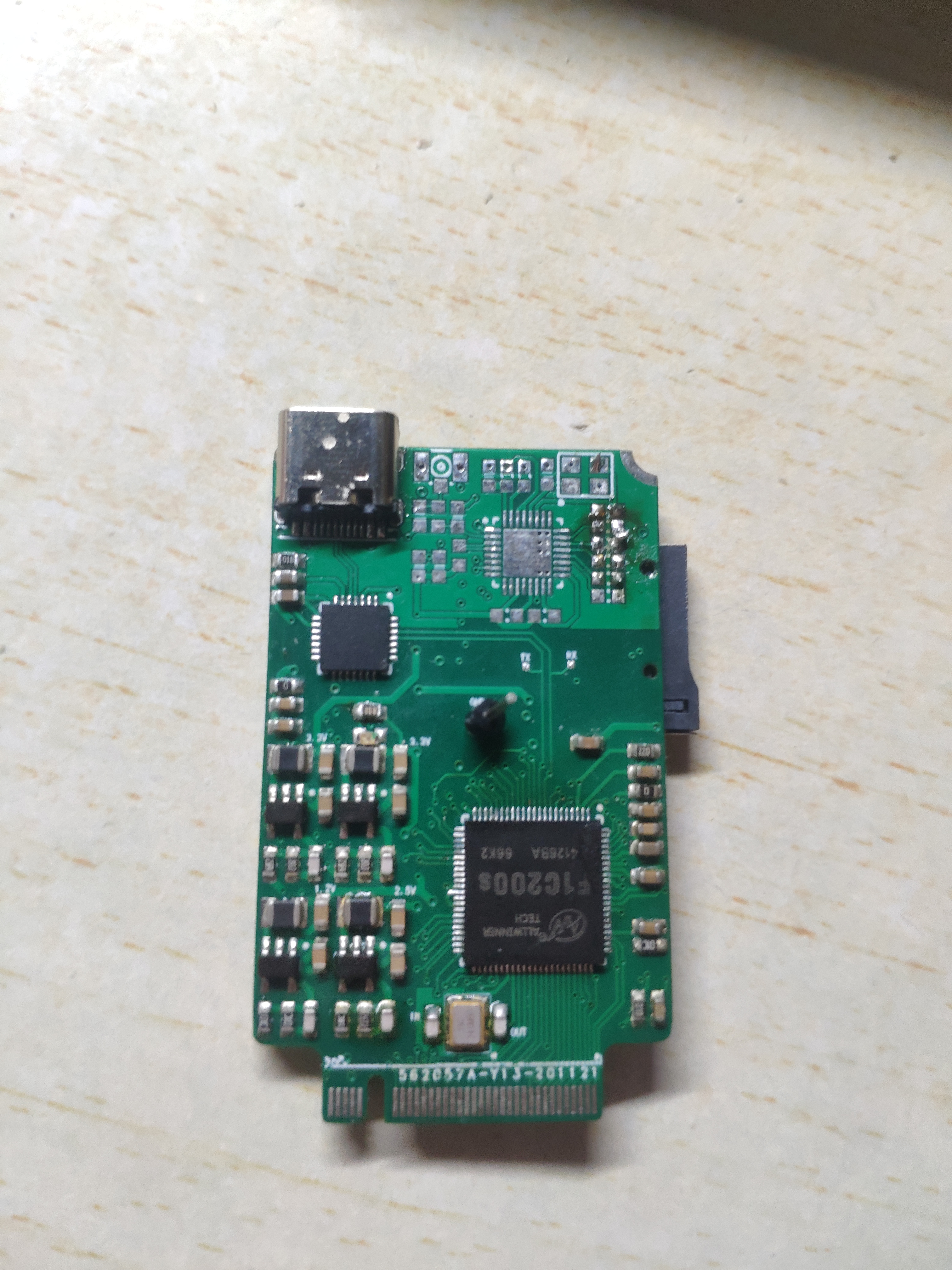
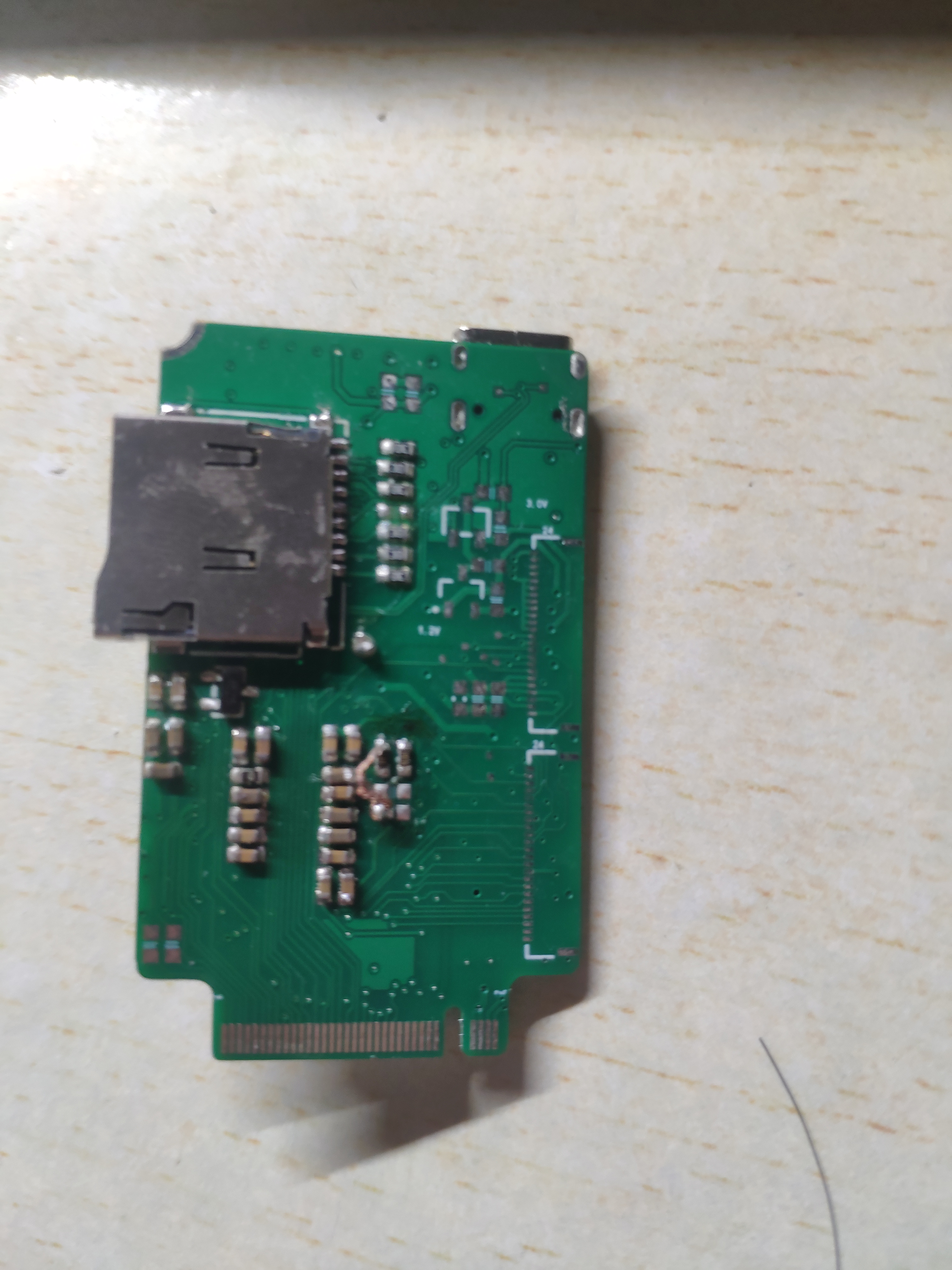
先晒板子图,四层,第二层为地,地层走了电源线,但是没有被分割开,WIFI和晶振下方区域在顶层和底层也覆铜(GND)。

板载CSI摄像头插件接口,SPI屏幕插件接口,ESP8266(ESP8086)-SPI,CP2102N
M.2引出了其余的接口(I2C,SDIO2(1-Pin),音频,多余的GPIO)
Type C双面切换串口和USB
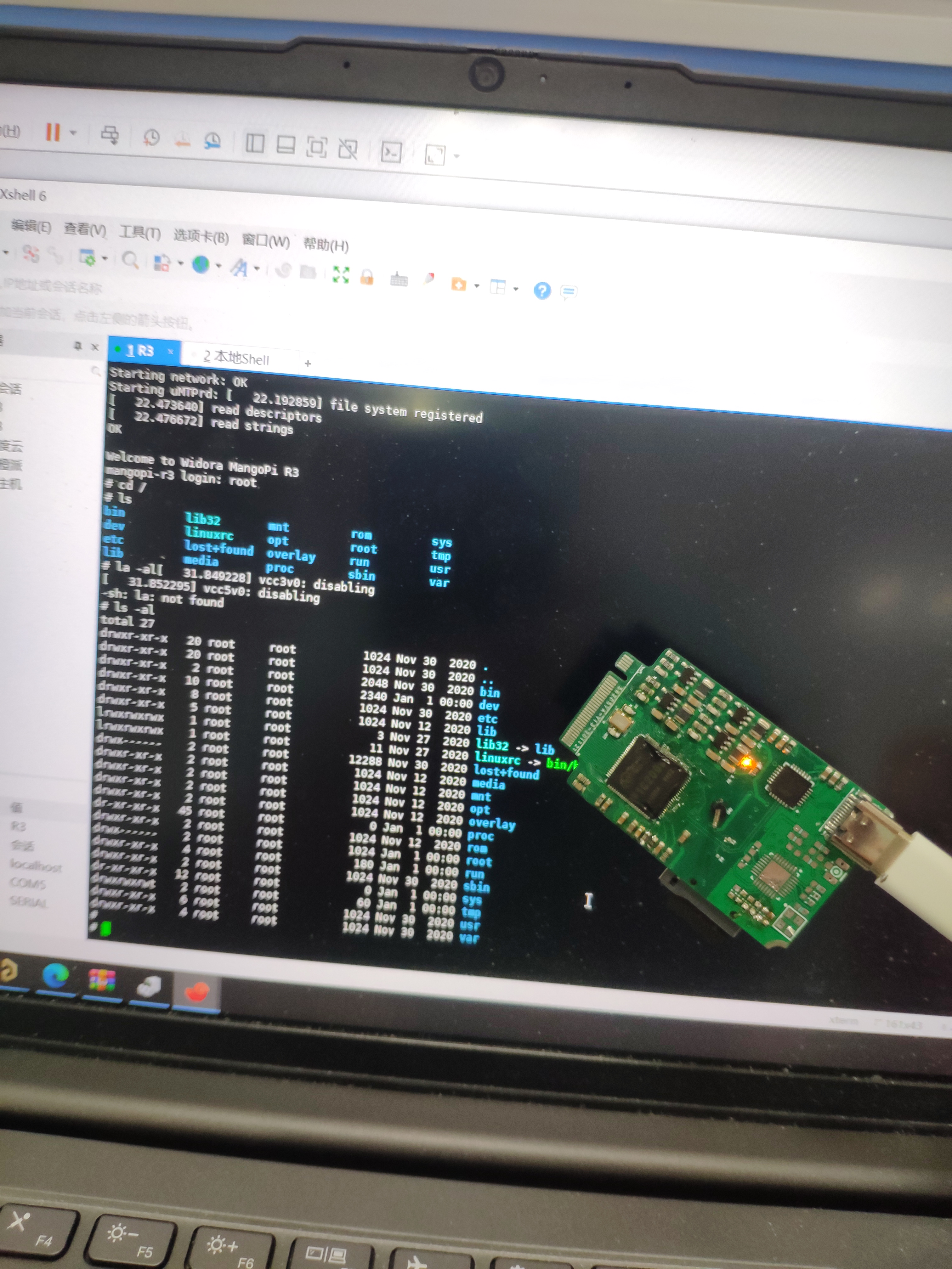
串口(波特115200)打印正常,Type C插上电脑可以识别(乌班图显示检测到Allwiner设备)。
出现的问题1:CNU[(AP92VFU8$RU(13.png)
分析:SD卡座里芯片有点远,还换层了,干扰可能比较重。
解决办法,调低MMC Clock频率为12M并且更换,SD卡(默认为24M)
调低频率后发现MMC没有报错了。
出现的问题2:
Trying to boot mmc0 就无反应了。
分析:Trying to boot mmc0应该是SPL加载U-boot主程序到DRAM中,SPL中成功初始化了MMC,并且SPL运行在芯片内部的RAM中,应该和MMC问题关系不大,重定向到DRAM中发生错误,应该就是芯片DRAM方向的问题了。
尝试解决办法:
1.检查供电,VCC-DRAM供电2.48V,纹波40mv。
2.DDR那 Svref管脚发现PCB中两个电阻和两个电容中少连一根线,导致Svref为80mv,去掉Vref的两个电容,接了根条小跳线后,插上SD卡芯片上电Svref为1.2V左右,但Trying to boot mmc0 后仍无反应。
3.U-boot配置中调低CONFIG_SYS_CLK_FREQ和CONFIG_DRAM_CLK,Trying to boot mmc0 后仍无反应。
初步怀疑是芯片的问题,等新芯片中,板子重画中。
有无大佬可以指点一下还可能是哪方面的问题。
在Debug的过程中,有几个疑问
1.SD卡的上拉电阻应该为多大比较好?我用的是10K,看有人用47K,上拉电阻这块是否有严格的规定?
2.VAR1和VAR2在荔枝派和芒果大佬做的R3板子部分有较大出入,这方面是否有要求?

主要区别在那个消失的200K的电阻
附上原理图原理图
有大佬可以检查一下我的原理图那非常感谢! 原理图我之前已经检查过很多遍了,没想到还是少连Svref那根线。
此贴会一直更新下去,一直到板载外设驱动移植成功。
页次: 1
- 首页
- » 搜索
- » Bosspoi 发表的帖子
太原小智科技有限责任公司 - 东莞哇酷科技有限公司联合开发
