- 首页
- » 搜索
- » guo_felix 发表的帖子
页次: 1
#1 Re: 全志 SOC » F1C100S跑linux如何更改LCD分辨率 » 2019-07-11 15:50:05
请教一下只能在uboot改吗?
我现在是尝试在f1c100s ,sunxi-fel 启动uboot,linux ,用晕哥固件是可以正常启动的,但分辨率不匹配。
尝试自己做uboot发现有如下的问题:
用suniv_f1c100s_tfcard_defconfig,通过改bootargs bootcmd 启动会有bad data CRC的问题:
具体bootargs bootcmd为:
bootargs=console=ttyS0,115200 panic=5 rootwait root=/dev/ram0 rdinit=/linuxrc earlyprintk
bootcmd=bootz 0x80008000 0x80D00000 0x80C00000
log:
   Image Name:
   Image Type:   ARM Linux RAMDisk Image (uncompressed)
   Data Size:    1840554 Bytes = 1.8 MiB
   Load Address: 00000000
   Entry Point:  00000000
   Verifying Checksum ... Bad Data CRC
Ramdisk image is corrupt or invalid
对比了下uboot启动log,晕哥上传的固件中没有 setting up a 272*480 lcd console,所以尝试在uboot中将关于lcd的去除:
ARM architechtur->Enable graphical uboot console on HDMI, LCD or VGA
Device Drivers->Graphics support 下的一些设置。
然后就可以正常启动了,有/dev/fb0 但分辨率为272480(我想改为800480),编译的lvgl例程也是可以显示,只是分辨率不对。
所以是关于显示功能覆盖了写入ramdisk的地方导致了校验问题?应该改源码也是可以的?望大家指教
#2 Re: 全志 SOC » 荔枝派zero/小智极客S3/V3s使用sunxi-fel 借 u-boot 启动 Linux系统, 无需 spi flash / TF 卡 » 2019-07-10 22:24:28
#3 Re: 全志 SOC » 荔枝派zero/小智极客S3/V3s使用sunxi-fel 借 u-boot 启动 Linux系统, 无需 spi flash / TF 卡 » 2019-07-10 20:20:49
晕哥 wrote:
Linux zero-4.13.y 和 buildroot 编译参考这个: 荔枝派Zero V3s开发板入坑记录 (TF/SD卡启动)(主线Linux,主线u-boot)
文件系统打包成 initramfs:
cd /opt/buildroot-2018.08.2/output/target
find . | cpio -o -Hnewc |gzip -9 > ../rootfs.cpio.gz
mkimage -A arm -T ramdisk -C none -n uInitrd -d ../rootfs.cpio.gz /var/www/html/rootfs.cpio.gz.uImage
mkimage -A arm -T ramdisk -C none -n uInitrd -d ../rootfs.cpio.gz ../rootfs.cpio.gz.uImage
(文件已经在一楼附件内)
请教一下晕哥 f1c100s initramfs制作是直接在buildroot中file system勾选 cpio 以及uboot image,然后是在buildroot system configure里面在/dev management里面要选上mdev,是吗?
这种和引用的这种用命令的方式有什么区别吗?因为一开始不知道,按照命令来做f1c100s的文件系统结果是无法挂载。
#4 Re: 全志 SOC » 荔枝派nano(f1c100s)的SPI-Flash系统编译创建全过程 » 2019-07-10 09:46:08
jiangming1399 wrote:
guo_felix wrote:
弱弱的问一句 fakeroot的作用是什么呢?
用fakeroot执行的命令,会被认为是以root用户ID执行的。在这里是为了让文件的所有者变为root,而不是打包时候的用户,防止在新的系统中出现文件权限问题。
对哦 仔细看了下确实有权限的差别,不过好像权限为1000时root也能改里面东西就是了,可能就是因为所有者为打包时的用户,但是在片上启动时文件系统里面又没有这个用户,谢谢解答!
lrwxrwxrwx    1 root     root             7 Jul  9  2019 bin -> usr/bin
drwxr-xr-x    5 root     root          2600 Jan  1 00:00 dev
drwxr-xr-x    5 root     root             0 Jan  1 00:00 etc
lrwxrwxrwx    1 root     root             7 Jul  9  2019 lib -> usr/lib
lrwxrwxrwx    1 root     root             3 Jul  9  2019 lib32 -> lib
lrwxrwxrwx    1 root     root            11 Jul  9  2019 linuxrc -> bin/busybox
drwxr-xr-x    2 root     root             0 Apr 29  2019 media
drwxr-xr-x    2 root     root             0 Apr 29  2019 mnt
drwxr-xr-x    2 root     root             0 Apr 29  2019 opt
dr-xr-xr-x   33 root     root             0 Jan  1 00:00 proc
drwx------    2 root     root             0 Jan  1 00:00 root
drwxr-xr-x    3 root     root           140 Jan  1 00:00 run
lrwxrwxrwx    1 root     root             8 Jul  9  2019 sbin -> usr/sbin
dr-xr-xr-x   12 root     root             0 Jan  1 00:00 sys
drwxrwxrwt    2 root     root            40 Jan  1 00:00 tmp
drwxr-xr-x    6 root     root             0 Jul  9  2019 usr
lrwxrwxrwx 1 1000 root 7 Jul 9 2019 bin -> usr/bin
drwxr-xr-x 5 root root 2600 Jan 1 00:00 dev
drwxr-xr-x 5 1000 root 0 Jan 1 00:00 etc
lrwxrwxrwx 1 1000 root 7 Jul 9 2019 lib -> usr/lib
lrwxrwxrwx 1 1000 root 3 Jul 9 2019 lib32 -> lib
lrwxrwxrwx 1 1000 root 11 Jul 9 2019 linuxrc -> bin/busybox
drwxr-xr-x 2 1000 root 0 Apr 29 2019 media
drwxr-xr-x 2 1000 root 0 Apr 29 2019 mnt
drwxr-xr-x 2 1000 root 0 Apr 29 2019 opt
dr-xr-xr-x 33 root root 0 Jan 1 00:00 proc
drwx------ 2 1000 root 0 Jan 1 00:00 root
drwxr-xr-x 3 root root 140 Jan 1 00:00 run
lrwxrwxrwx 1 1000 root 8 Jul 9 2019 sbin -> usr/sbin
dr-xr-xr-x 12 root root 0 Jan 1 00:00 sys
drwxrwxrwt 2 root root 40 Jan 1 00:00 tmp
drwxr-xr-x 6 1000 root 0 Jul 9 2019 usr
drwxr-xr-x 4 1000 root 0 Jul 9 2019 var#6 Re: 全志 SOC » 请教一下关于lichee nano在官网上电容屏的适配 » 2019-05-24 11:30:24
运行ts_calibrate 也没有问题,可以成功校准,但是只相对于tslib来说有校准,对于littlevgl直接读取/input/event的时候触屏还是会有问题。
在网上看到有方法改写 evdev.c中的几个读取函数,用tslib来实现,这样就可以利用到运行test_calibrate得到的参数。
具体方法如下网址:
[[笔记]在嵌入式linux上运行LittlevGL GUI demo 支持tslib(出处: amoBBS 阿莫电子论坛)](<https://www.amobbs.com/thread-5709606-1-1.html>)
实际就是改evdev_init 以及 evdev_read两个函数
算是分享一下和官网上不同的校准方式吧
#7 Re: 全志 SOC » 请教一下关于lichee nano在官网上电容屏的适配 » 2019-05-23 22:33:53
#8 Re: 全志 SOC » 请教一下关于lichee nano在官网上电容屏的适配 » 2019-05-23 16:28:33
注意到原理图中 电容屏中断口连接的是PE3?
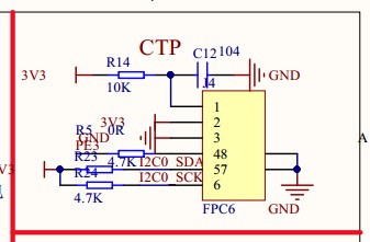
而且实际复位端口也是直接用了RC,即图中1口,实际dts并没有配置到gt911的中断端口以及复位端口?
尝试如下修改,不过好像没什么用处:
	gt911:touchscreen@14{
		compatible = "goodix,gt911";
		reg = <0x14>;
		interrupt-parent = <&pio>;
		interrupts = <4 3 IRQ_TYPE_EDGE_FALLING>;/*(PE3)*/
		pinctrl-names = "default";
		pinctrl-0 = <&ts_reset_pin>;
		irq-gpios = <&pio 4 3 GPIO_ACTIVE_HIGH>;/*(PE3)*/
		reset-gpios = <&pio 4 9 GPIO_ACTIVE_HIGH>; /*RST (PE9)*/
		/*touchscreen-swapped-x-y*/
		};
还想请问一下,如果中断配置成功的话,是不是/dev/下就会有input文件夹,因为现在板上一直是没有这个文件夹
#9 Re: 全志 SOC » 请教一下关于lichee nano在官网上电容屏的适配 » 2019-05-23 15:44:59
谢谢晕哥 之前一直怀疑设备树写得有问题 检测了好几遍,也确实检查出了问题。后来尝试控制PE11 和PE12,发现抓从底板上引出来的PE12没办法拉低,但cat value 又确实是0,最后发现是核心板和底板就这个脚虚焊了 现在i2cdetect:
# i2cdetect -y -r 0
     0  1  2  3  4  5  6  7  8  9  a  b  c  d  e  f
00:          -- -- -- -- -- -- -- -- -- -- -- -- --
10: -- -- -- -- -- -- -- -- -- -- -- -- -- -- -- --
20: -- -- -- -- -- -- -- -- -- -- -- -- -- -- -- --
30: -- -- -- -- -- -- -- -- -- -- -- -- -- -- -- --
40: -- -- -- -- -- -- -- -- -- -- -- -- -- -- -- --
50: -- -- -- -- -- -- -- -- -- -- -- -- -- 5d -- --
60: -- -- -- -- -- -- -- -- -- -- -- -- -- -- -- --
70: -- -- -- -- -- -- -- --
虽然log中好像关于触屏的驱动还是有问题:
[    0.663484] i2c /dev entries driver
[    0.781273] Goodix-TS 0-0014: i2c test failed attempt 1: -6
[    0.821241] Goodix-TS 0-0014: i2c test failed attempt 2: -6
[    0.861061] Goodix-TS 0-0014: I2C communication failure: -6
但至少I2c是没问题的了
#10 Re: 全志 SOC » 请教一下关于lichee nano在官网上电容屏的适配 » 2019-05-23 11:33:47
尝试了一下 确实是 我以为不会自适应宽度 想多了
#11 Re: 全志 SOC » 请教一下关于lichee nano在官网上电容屏的适配 » 2019-05-23 11:32:17
以下为 suniv.dtsi
// SPDX-License-Identifier: (GPL-2.0+ OR X11)
/*
 * Copyright 2018 Icenowy Zheng <icenowy@aosc.io>
 */

#include <dt-bindings/clock/suniv-ccu.h>
#include <dt-bindings/reset/suniv-ccu.h>

/ {
	#address-cells = <1>;
	#size-cells = <1>;
	interrupt-parent = <&intc>;

	clocks {
		#address-cells = <1>;
		#size-cells = <1>;
		ranges;

		osc24M: clk-24M {
			#clock-cells = <0>;
			compatible = "fixed-clock";
			clock-frequency = <24000000>;
			clock-output-names = "osc24M";
		};

		osc32k: clk-32k {
			#clock-cells = <0>;
			compatible = "fixed-clock";
			clock-frequency = <32768>;
			clock-output-names = "osc32k";
		};

		fake100M: clk-100M {
			#clock-cells = <0>;
			compatible = "fixed-clock";
			clock-frequency = <100000000>;
			clock-output-names = "fake-100M";
		};
	};

	cpus {
		#address-cells = <0>;
		#size-cells = <0>;

		cpu {
			compatible = "arm,arm926ej-s";
			device_type = "cpu";
		};
	};

	de: display-engine {
		compatible = "allwinner,suniv-display-engine";
		allwinner,pipelines = <&fe0>;
		status = "disabled";
	};

	soc {
		compatible = "simple-bus";
		#address-cells = <1>;
		#size-cells = <1>;
		ranges;

		sram-controller@1c00000 {
			compatible = "allwinner,sun4i-a10-sram-controller";
			reg = <0x01c00000 0x30>;
			#address-cells = <1>;
			#size-cells = <1>;
			ranges;

			sram_d: sram@10000 {
				compatible = "mmio-sram";
				reg = <0x00010000 0x1000>;
				#address-cells = <1>;
				#size-cells = <1>;
				ranges = <0 0x00010000 0x1000>;

				otg_sram: sram-section@0 {
					compatible = "allwinner,sun4i-a10-sram-d";
					reg = <0x0000 0x1000>;
					status = "disabled";
				};
			};
		};

		spi0: spi@1c05000 {
			compatible = "allwinner,suniv-spi",
				     "allwinner,sun8i-h3-spi";
			reg = <0x01c05000 0x1000>;
			interrupts = <10>;
			clocks = <&ccu CLK_BUS_SPI0>, <&ccu CLK_BUS_SPI0>;
			clock-names = "ahb", "mod";
			resets = <&ccu RST_BUS_SPI0>;
			status = "disabled";
			#address-cells = <1>;
			#size-cells = <0>;
		};

		spi1: spi@1c06000 {
			compatible = "allwinner,suniv-spi",
				     "allwinner,sun8i-h3-spi";
			reg = <0x01c06000 0x1000>;
			interrupts = <11>;
			clocks = <&ccu CLK_BUS_SPI1>, <&ccu CLK_BUS_SPI1>;
			clock-names = "ahb", "mod";
			resets = <&ccu RST_BUS_SPI1>;
			status = "disabled";
			#address-cells = <1>;
			#size-cells = <0>;
		};

		tcon0: lcd-controller@1c0c000 {
			compatible = "allwinner,suniv-tcon";
			reg = <0x01c0c000 0x1000>;
			interrupts = <29>;
			clocks = <&ccu CLK_BUS_LCD>,
				 <&ccu CLK_TCON>,
				 <&osc24M>;	/* Still unknown */
			clock-names = "ahb",
				      "tcon-ch0",
				      "tcon-ch1";
			clock-output-names = "tcon-pixel-clock";
			resets = <&ccu RST_BUS_LCD>;
			reset-names = "lcd";
			status = "disabled";

			ports {
				#address-cells = <1>;
				#size-cells = <0>;

				tcon0_in: port@0 {
					#address-cells = <1>;
					#size-cells = <0>;
					reg = <0>;

					tcon0_in_be0: endpoint@0 {
						reg = <0>;
						remote-endpoint = <&be0_out_tcon0>;
					};
				};

				tcon0_out: port@1 {
					#address-cells = <1>;
					#size-cells = <0>;
					reg = <1>;
				};
			};
		};

		mmc0: mmc@1c0f000 {
			compatible = "allwinner,suniv-mmc",
				     "allwinner,sun7i-a20-mmc";
			reg = <0x01c0f000 0x1000>;
			clocks = <&ccu CLK_BUS_MMC0>,
				 <&ccu CLK_MMC0>,
				 <&ccu CLK_MMC0_OUTPUT>,
				 <&ccu CLK_MMC0_SAMPLE>;
			clock-names = "ahb",
				      "mmc",
				      "output",
				      "sample";
			resets = <&ccu RST_BUS_MMC0>;
			reset-names = "ahb";
			interrupts = <23>;
			pinctrl-names = "default";
			pinctrl-0 = <&mmc0_pins>;
			status = "disabled";
			#address-cells = <1>;
			#size-cells = <0>;
		};

		mmc1: mmc@1c10000 {
			compatible = "allwinner,suniv-mmc",
				     "allwinner,sun7i-a20-mmc";
			reg = <0x01c10000 0x1000>;
			clocks = <&ccu CLK_BUS_MMC1>,
				 <&ccu CLK_MMC1>,
				 <&ccu CLK_MMC1_OUTPUT>,
				 <&ccu CLK_MMC1_SAMPLE>;
			clock-names = "ahb",
				      "mmc",
				      "output",
				      "sample";
			resets = <&ccu RST_BUS_MMC1>;
			reset-names = "ahb";
			interrupts = <24>;
			status = "disabled";
			#address-cells = <1>;
			#size-cells = <0>;
		};

		ccu: clock@1c20000 {
			compatible = "allwinner,suniv-ccu";
			reg = <0x01c20000 0x400>;
			clocks = <&osc24M>, <&osc32k>;
			clock-names = "hosc", "losc";
			#clock-cells = <1>;
			#reset-cells = <1>;
		};

		intc: interrupt-controller@1c20400 {
			compatible = "allwinner,suniv-ic";
			reg = <0x01c20400 0x400>;
			interrupt-controller;
			#interrupt-cells = <1>;
		};

		pio: pinctrl@1c20800 {
			compatible = "allwinner,suniv-pinctrl";
			reg = <0x01c20800 0x400>;
			interrupts = <38>, <39>, <40>;
			clocks = <&ccu CLK_BUS_PIO>, <&osc24M>, <&osc32k>;
			clock-names = "apb", "hosc", "losc";
			gpio-controller;
			interrupt-controller;
			#interrupt-cells = <3>;
			#gpio-cells = <3>;

			spi0_pins_a: spi0-pins-pc {
				pins = "PC0", "PC1", "PC2", "PC3";
				function = "spi0";
			};

			lcd_rgb666_pins: lcd-rgb666-pins {
				pins = "PD1", "PD2", "PD3", "PD4",
				       "PD5", "PD6", "PD7", "PD8", "PD9",
				       "PD10", "PD11", "PD13", "PD14",
				       "PD15", "PD16", "PD17", "PD18", "PD19",
				       "PD20", "PD21";
				function = "lcd";
			};

			uart0_pins_a: uart-pins-pe {
				pins = "PE0", "PE1";
				function = "uart0";
			};

			uart2_pins_a: uart2-pins-pe {
				pins = "PE7", "PE8";
				function = "uart2";
			};

			mmc0_pins: mmc0-pins {
				pins = "PF0", "PF1", "PF2", "PF3", "PF4", "PF5";
				function = "mmc0";
			};
			i2c0_pins: i2c0 {
				pins = "PE11", "PE12";
				function = "i2c0";
			};

		};

		timer@1c20c00 {
			compatible = "allwinner,suniv-timer";
			reg = <0x01c20c00 0x90>;
			interrupts = <13>;
			clocks = <&osc24M>;
		};

		wdt: watchdog@1c20ca0 {
			compatible = "allwinner,sun6i-a31-wdt";
			reg = <0x01c20ca0 0x20>;
		};

		uart0: serial@1c25000 {
			compatible = "snps,dw-apb-uart";
			reg = <0x01c25000 0x400>;
			interrupts = <1>;
			reg-shift = <2>;
			reg-io-width = <4>;
			clocks = <&ccu CLK_BUS_UART0>;
			resets = <&ccu RST_BUS_UART0>;
			status = "disabled";
		};

		uart1: serial@1c25400 {
			compatible = "snps,dw-apb-uart";
			reg = <0x01c25400 0x400>;
			interrupts = <2>;
			reg-shift = <2>;
			reg-io-width = <4>;
			clocks = <&ccu CLK_BUS_UART1>;
			resets = <&ccu RST_BUS_UART1>;
			status = "disabled";
		};

		uart2: serial@1c25800 {
			compatible = "snps,dw-apb-uart";
			reg = <0x01c25800 0x400>;
			interrupts = <3>;
			reg-shift = <2>;
			reg-io-width = <4>;
			clocks = <&ccu CLK_BUS_UART2>;
			resets = <&ccu RST_BUS_UART2>;
			status = "disabled";
		};

		usb_otg: usb@1c13000 {
			compatible = "allwinner,suniv-musb";
			reg = <0x01c13000 0x0400>;
			clocks = <&ccu CLK_BUS_OTG>;
			resets = <&ccu RST_BUS_OTG>;
			interrupts = <26>;
			interrupt-names = "mc";
			phys = <&usbphy 0>;
			phy-names = "usb";
			extcon = <&usbphy 0>;
			allwinner,sram = <&otg_sram 1>;
			status = "disabled";
		};

		usbphy: phy@1c13400 {
			compatible = "allwinner,suniv-usb-phy";
			reg = <0x01c13400 0x10>;
			reg-names = "phy_ctrl";
			clocks = <&ccu CLK_USB_PHY0>;
			clock-names = "usb0_phy";
			resets = <&ccu RST_USB_PHY0>;
			reset-names = "usb0_reset";
			#phy-cells = <1>;
			status = "disabled";
		};

		fe0: display-frontend@1e00000 {
			compatible = "allwinner,suniv-display-frontend";
			reg = <0x01e00000 0x20000>;
			interrupts = <30>;
			clocks = <&ccu CLK_BUS_DE_FE>, <&ccu CLK_DE_FE>,
				 <&ccu CLK_DRAM_DE_FE>;
			clock-names = "ahb", "mod",
				      "ram";
			resets = <&ccu RST_BUS_DE_FE>;
			status = "disabled";

			ports {
				#address-cells = <1>;
				#size-cells = <0>;

				fe0_out: port@1 {
					#address-cells = <1>;
					#size-cells = <0>;
					reg = <1>;

					fe0_out_be0: endpoint@0 {
						reg = <0>;
						remote-endpoint = <&be0_in_fe0>;
					};
				};
			};
		};

		be0: display-backend@1e60000 {
			compatible = "allwinner,suniv-display-backend";
			reg = <0x01e60000 0x10000>;
			reg-names = "be";
			interrupts = <31>;
			clocks = <&ccu CLK_BUS_DE_BE>, <&ccu CLK_DE_BE>,
				 <&ccu CLK_DRAM_DE_BE>;
			clock-names = "ahb", "mod",
				      "ram";
			resets = <&ccu RST_BUS_DE_BE>;
			reset-names = "be";
			assigned-clocks = <&ccu CLK_DE_BE>;
			assigned-clock-rates = <300000000>;

			ports {
				#address-cells = <1>;
				#size-cells = <0>;

				be0_in: port@0 {
					#address-cells = <1>;
					#size-cells = <0>;
					reg = <0>;

					be0_in_fe0: endpoint@0 {
						reg = <0>;
						remote-endpoint = <&fe0_out_be0>;
					};
				};

				be0_out: port@1 {
					#address-cells = <1>;
					#size-cells = <0>;
					reg = <1>;

					be0_out_tcon0: endpoint@0 {
						reg = <0>;
						remote-endpoint = <&tcon0_in_be0>;
					};
				};
			};
		};

		i2c0: i2c@1C27000{

					compatible = "allwinner,sun6i-a31-i2c";
					reg = <0x01c27000 0x400>;
					interrupts = <7>;
					clocks = <&ccu CLK_BUS_I2C0>;
					resets = <&ccu RST_BUS_I2C0>;
					pinctrl-names = "default";
					pinctrl-0 = <&i2c0_pins>;
					status = "disabled";
					#address-cells = <1>;
					#size-cells = <0>;

				};

	};
};
以下为 suniv-f1c100s-licheepi-nano.dts:
// SPDX-License-Identifier: (GPL-2.0+ OR X11)
/*
* Copyright 2018 Icenowy Zheng <icenowy@aosc.io>
*/
/dts-v1/;
#include "suniv-f1c100s.dtsi"
#include <dt-bindings/gpio/gpio.h>
// touch screen
#include <dt-bindings/input/input.h>
#include <dt-bindings/interrupt-controller/irq.h>
/ {
model = "Lichee Pi Nano";
compatible = "licheepi,licheepi-nano", "allwinner,suniv-f1c100s",
"allwinner,suniv";
aliases {
serial0 = &uart0;
spi0 = &spi0;
};
chosen {
stdout-path = "serial0:115200n8";
};
panel: panel {
compatible = "lg,lb070wv8", "simple-panel";
#address-cells = <1>;
#size-cells = <0>;
enable-gpios = <&pio 4 5 GPIO_ACTIVE_HIGH>;
port@0 {
reg = <0>;
#address-cells = <1>;
#size-cells = <0>;
panel_input: endpoint@0 {
reg = <0>;
remote-endpoint = <&tcon0_out_lcd>;
};
};
};
reg_vcc3v3: vcc3v3 {
compatible = "regulator-fixed";
regulator-name = "vcc3v3";
regulator-min-microvolt = <3300000>;
regulator-max-microvolt = <3300000>;
};
};
&de {
status = "okay";
};
&mmc0 {
vmmc-supply = <®_vcc3v3>;
bus-width = <4>;
broken-cd;
status = "okay";
};
&otg_sram {
status = "okay";
};
&spi0 {
pinctrl-names = "default";
pinctrl-0 = <&spi0_pins_a>;
status = "okay";
flash@0 {
#address-cells = <1>;
#size-cells = <1>;
compatible = "winbond,w25q128", "jedec,spi-nor";
reg = <0>;
spi-max-frequency = <40000000>;
};
};
&tcon0 {
pinctrl-names = "default";
pinctrl-0 = <&lcd_rgb666_pins>;
status = "okay";
};
&tcon0_out {
tcon0_out_lcd: endpoint@0 {
reg = <0>;
remote-endpoint = <&panel_input>;
};
};
&uart0 {
pinctrl-names = "default";
pinctrl-0 = <&uart0_pins_a>;
status = "okay";
};
&uart2 {
pinctrl-names = "default";
pinctrl-0 = <&uart2_pins_a>;
status = "okay";
};
&usb_otg {
dr_mode = "otg";
status = "okay";
};
&usbphy {
usb0_id_det-gpio = <&pio 4 2 GPIO_ACTIVE_HIGH>; /* PE2 */
status = "okay";
};
&i2c0{
pinctrl-0 = <&i2c0_pins>;
pinctrl-names = "default";
status = "okay";
gt911:touchscreen@14{
compatible = "goodix,gt911";
reg = <0x14>;
interrupt-parent = <&pio>;
interrupts = <4 10 IRQ_TYPE_EDGE_FALLING>;/*(PE10)*/
pinctrl-names = "default";
pinctrl-0 = <&ts_reset_pin>;
irq-gpios = <&pio 4 10 GPIO_ACTIVE_HIGH>;/*(PE10>*/
reset-gpios = <&pio 4 9 GPIO_ACTIVE_HIGH>; /*RST (PE9)*/
/*touchscreen-swapped-x-y*/
};
};
&pio {
ts_reset_pin:ts_reset_pin@0{
pins = "PE9";
function = "gpio_out";
};
};#12 Re: 全志 SOC » 请教一下关于lichee nano在官网上电容屏的适配 » 2019-05-23 11:27:54
#13 Re: 全志 SOC » 请教一下关于lichee nano在官网上电容屏的适配 » 2019-05-23 11:24:29
#14 全志 SOC » 请教一下关于lichee nano在官网上电容屏的适配 » 2019-05-23 10:51:24
- guo_felix
- 回复: 30
底板 电容屏也是官网的 gt911
大概步骤就是在dtsi中(soc,pio节点)加节点 然后在dts中引用 http://nano.lichee.pro/build_sys/devicetree.html#id5
内核中已经勾选Gooddix I2C touchscreen ,启动log会报如下信息:
[    0.663532] i2c /dev entries driver
[    2.881100] i2c i2c-0: mv64xxx: I2C bus locked, block: 1, time_left: 0
[    2.887655] Goodix-TS 0-0014: i2c test failed attempt 1: -110
[    5.041092] i2c i2c-0: mv64xxx: I2C bus locked, block: 1, time_left: 0
[    5.047634] Goodix-TS 0-0014: i2c test failed attempt 2: -110
[    5.091084] Goodix-TS 0-0014: I2C communication failure: -110
[    5.096951] Goodix-TS: probe of 0-0014 failed with error -110
i2cdetect -l 命令输出如下:
i2c-0 i2c mv64xxx_i2c adapter I2C adapteri2cdetect -r -y 0 输出如下:
# i2cdetect -r -y 0
     0  1  2  3  4  5  6  7  8  9  a  b  c  d  e  f
00:          [ 1116.081094] i2c i2c-0: mv64xxx: I2C bus locked, block: 1, time_left: 0
-- [ 1118.161097] i2c i2c-0: mv64xxx: I2C bus locked, block: 1, time_left: 0
i2cset 也是会报I2C bus locked。
看原理图底板应该是有上拉的
不知道有没有人遇到过同样的情况,是我dts改错了吗?
照这个情况是不是cpu根本就没发出i2c信号?
还是如果根本就没接上也会有这种情况?
#15 Re: 全志 SOC » 各位大神有弄过电容屏的触摸吗 不是电阻屏 » 2019-05-22 15:45:14
#16 Re: 全志 SOC » 各位大神有弄过电容屏的触摸吗 不是电阻屏 » 2019-05-22 09:46:22
#17 Re: 全志 SOC » 各位大神有弄过电容屏的触摸吗 不是电阻屏 » 2019-05-22 09:20:26
晕哥 wrote:
/files/members/3/2019-05-22_081908.png
荔枝派zero核心板pdf: /files/20171005/11/lichee_zero(核心板).pdf
第三页最底下
谢谢晕哥 不好意思 我忘记说了 我用的是nano的板子,文档中I2C如下:
实际是照官方文档添加设备树来的,只是说/dev 下没有input这个文件夹,内核中是直接勾选的触屏,应该也不存在文档中有加载模块的问题。如果说出现I2C bus lock 是不是也会导致/dev/input 不存在?
看控制台输出感觉i2c接口是没有问题的,不过以防万一还是测了下,上电后 SDA SCK是可以被拉高的,是我设备树改得有问题吗
#18 Re: 全志 SOC » 各位大神有弄过电容屏的触摸吗 不是电阻屏 » 2019-05-21 23:09:51
#19 Re: 全志 SOC » 各位大神有弄过电容屏的触摸吗 不是电阻屏 » 2019-05-21 22:47:54
想请教一下 内核启动后 i2c显示这些东西 是我内核没配置好吗
[    2.880959] i2c i2c-0: mv64xxx: I2C bus locked, block: 1, time_left: 0
[    2.887524] Goodix-TS 0-0014: i2c test failed attempt 1: -110
[    5.040934] i2c i2c-0: mv64xxx: I2C bus locked, block: 1, time_left: 0
[    5.047478] Goodix-TS 0-0014: i2c test failed attempt 2: -110
[    5.090934] Goodix-TS 0-0014: I2C communication failure: -110
[ 5.096809] Goodix-TS: probe of 0-0014 failed with error -110#20 Re: 全志 SOC » 请教,在ubuntu上编译了SDL2的一个简单demo程序,该怎么交叉编译到F1C100S上呢? » 2019-05-20 18:57:22
晕哥 wrote:
如果想省事就直接用 buildroot,
开启 BR2_PACKAGE_SDL 编译开关即可,勾选SDL就自动加入了 framebuffer 功能
编译之后就会直接生成文件系统,
请问一下 讲道理是不是buildroot中加了选项 /output/target/lib就会有相应的库 然后直接在交叉编译应用的时候-L进来就好了
#21 Re: 计算机图形/GUI/RTOS/FileSystem/OpenGL/DirectX/SDL2 » 一步一步分享在Windows QtCreator/Mingw平台编译运行调试LittleVGL » 2018-04-12 20:29:22
页次: 1
- 首页
- » 搜索
- » guo_felix 发表的帖子
东莞哇酷科技有限公司开发