- 首页
- » 搜索
- » armstrong 发表的帖子
#6 Re: 全志 SOC » 跟贴从零构建f1c200s硬件开发板 » 2025-03-07 13:05:22
#7 Re: 全志 SOC » f1c200s,经常会死机 » 2025-03-07 12:59:10
#8 Re: 工业芯 匠芯创 » 一维码+二维码识别方案 » 2024-12-11 22:04:57
#10 Re: 全志 SOC » libxnes开源了,这是一款纯C99标准拥有超强的可移植性,可读性,可玩性的高精度NES模拟器库,纯手写打造,感兴趣的可以在这帖子里恰饭。 » 2024-10-22 15:58:45
#11 Re: 计算机图形/GUI/RTOS/FileSystem/OpenGL/DirectX/SDL2 » FreeRTOS运行Lvgl,应该如何设计框架的? » 2024-10-15 11:52:39
#12 Re: 全志 SOC » libxnes开源了,这是一款纯C99标准拥有超强的可移植性,可读性,可玩性的高精度NES模拟器库,纯手写打造,感兴趣的可以在这帖子里恰饭。 » 2024-10-11 14:02:13
#13 Re: 全志 SOC » libxnes开源了,这是一款纯C99标准拥有超强的可移植性,可读性,可玩性的高精度NES模拟器库,纯手写打造,感兴趣的可以在这帖子里恰饭。 » 2024-10-11 13:55:34
#14 Re: 全志 SOC » libxnes开源了,这是一款纯C99标准拥有超强的可移植性,可读性,可玩性的高精度NES模拟器库,纯手写打造,感兴趣的可以在这帖子里恰饭。 » 2024-10-09 21:03:33
#15 Re: 全志 SOC » libxnes开源了,这是一款纯C99标准拥有超强的可移植性,可读性,可玩性的高精度NES模拟器库,纯手写打造,感兴趣的可以在这帖子里恰饭。 » 2024-10-09 21:00:05
#16 Re: 全志 SOC » libxnes开源了,这是一款纯C99标准拥有超强的可移植性,可读性,可玩性的高精度NES模拟器库,纯手写打造,感兴趣的可以在这帖子里恰饭。 » 2024-10-09 20:57:50
armstrong 说:各种mapper是有标准的吗?还是全靠逆向分析出来的?
好全的nes资料啊,多谢分享
#17 Re: 全志 SOC » libxnes开源了,这是一款纯C99标准拥有超强的可移植性,可读性,可玩性的高精度NES模拟器库,纯手写打造,感兴趣的可以在这帖子里恰饭。 » 2024-10-09 15:38:18
#18 Re: 全志 SOC » libxnes开源了,这是一款纯C99标准拥有超强的可移植性,可读性,可玩性的高精度NES模拟器库,纯手写打造,感兴趣的可以在这帖子里恰饭。 » 2024-10-09 15:26:20
#19 Re: 全志 SOC » libxnes开源了,这是一款纯C99标准拥有超强的可移植性,可读性,可玩性的高精度NES模拟器库,纯手写打造,感兴趣的可以在这帖子里恰饭。 » 2024-10-09 14:48:58
#20 Re: 全志 SOC » libxnes开源了,这是一款纯C99标准拥有超强的可移植性,可读性,可玩性的高精度NES模拟器库,纯手写打造,感兴趣的可以在这帖子里恰饭。 » 2024-10-09 14:46:31
#21 Re: 工业芯 匠芯创 » 请教下Linux下研发的工具和各种文档 » 2024-09-18 20:05:02
#22 Re: 工业芯 匠芯创 » 请教下Linux下研发的工具和各种文档 » 2024-09-18 20:04:24
#23 Re: 全志 SOC » 有钱了,咱也能用上64位CPU了,入坑H618 » 2024-09-15 12:39:45
#24 Re: 全志 SOC » F1C100s用DMA加速spiflash启动 » 2024-09-03 19:55:59
DOUT+DMA模式,太快了!若SPI时钟设为100MHZ,能达到25MB/S;保险起见设置SPI为50MHZ,也有12.5MB/S。
启动个RTOS应用简直了。
#include <stdint.h>
#include <string.h>
#include "f1c100s/reg-ccu.h"
#include "io.h"

#define SPI_USE_DMA (1)

enum {
  SPI_GCR = 0x04,
  SPI_TCR = 0x08,
  SPI_IER = 0x10,
  SPI_ISR = 0x14,
  SPI_FCR = 0x18,
  SPI_FSR = 0x1c,
  SPI_WCR = 0x20,
  SPI_CCR = 0x24,
  SPI_MBC = 0x30,
  SPI_MTC = 0x34,
  SPI_BCC = 0x38,
  SPI_TXD = 0x200,
  SPI_RXD = 0x300,
};

#if SPI_USE_DMA > 0

enum {
  DMA0 = 0,
  DMA1,
  DMA2,
  DMA3,
};

enum {
  NDMA = 0,
  DDMA,
};

#define NDMA_TRANS_LEN  (128u*1024)
#define DDMA_TRANS_LEN  (16u*1024*1024)

/********** DMA info *************/
#define DMA_NO        (DMA0)
#define DMA_MODE      (NDMA)  /* SPI only support NDMA */
#define DMA_TRANS_LEN ((DMA_MODE == NDMA) ? (NDMA_TRANS_LEN) : (DDMA_TRANS_LEN))

#define DMA_BASE              (0x01C02000)

#define DMA_ICR               (DMA_BASE + 0x00)
#define DMA_ISR               (DMA_BASE + 0x04)
#define DMA_PCR               (DMA_BASE + 0x08)

#define NDMA_CR(dma_n)        (DMA_BASE + 0x100 + 0x20*dma_n + 0x0)
#define NDMA_SRC_ADDR(dma_n)  (DMA_BASE + 0x100 + 0x20*dma_n + 0x4)
#define NDMA_DES_ADDR(dma_n)  (DMA_BASE + 0x100 + 0x20*dma_n + 0x8)
#define NDMA_BCR(dma_n)       (DMA_BASE + 0x100 + 0x20*dma_n + 0xC)

#define DDMA_CR(dma_n)        (DMA_BASE + 0x300 + 0x20*dma_n + 0x0)
#define DDMA_SRC_ADDR(dma_n)  (DMA_BASE + 0x300 + 0x20*dma_n + 0x4)
#define DDMA_DES_ADDR(dma_n)  (DMA_BASE + 0x300 + 0x20*dma_n + 0x8)
#define DDMA_BCR(dma_n)       (DMA_BASE + 0x300 + 0x20*dma_n + 0xC)
#define DDMA_PR(dma_n)        (DMA_BASE + 0x300 + 0x20*dma_n + 0x18)
#define DDMA_GD(dma_n)        (DMA_BASE + 0x300 + 0x20*dma_n + 0x1C)

static void sdelay(int loops)
{
loop_again:
  __asm volatile {
    SUBS loops, loops, #1
    BNE loop_again
  }
}

static void sys_dma_init(void)
{
  /* Enable gate for DMA clock, and perform softreset */
  write32(F1C100S_CCU_BASE + CCU_BUS_CLK_GATE0, read32(F1C100S_CCU_BASE + CCU_BUS_CLK_GATE0) | (0x1 << 6));
  write32(F1C100S_CCU_BASE + CCU_BUS_SOFT_RST0, read32(F1C100S_CCU_BASE + CCU_BUS_SOFT_RST0) & (~(0x1 << 6)));
  sdelay(20);
  write32(F1C100S_CCU_BASE + CCU_BUS_SOFT_RST0, read32(F1C100S_CCU_BASE + CCU_BUS_SOFT_RST0) | (0x1 << 6));
}

static void sys_dma_deinit(void)
{
  write32(F1C100S_CCU_BASE + CCU_BUS_CLK_GATE0, read32(F1C100S_CCU_BASE + CCU_BUS_CLK_GATE0) & (~(0x1 << 6)));
}

static uint32_t sys_dma_transfer_len_get(void)
{
  return DMA_TRANS_LEN;
}

static void sys_spi_dma_set(void* dst, void* src, uint32_t len)
{
  uint32_t val;

  write32(NDMA_SRC_ADDR(DMA_NO), (uint32_t)src);
  write32(NDMA_DES_ADDR(DMA_NO), (uint32_t)dst);
  write32(NDMA_BCR(DMA_NO), len);

  val = (1u << 31) | (0x11 << 16) | (0x1 << 5) | (0x4 << 0);
  write32(NDMA_CR(DMA_NO), val);
}

static void sys_spi_dma_start(uint32_t len)
{
  uint32_t reg_base = 0x01c05000;
  uint32_t val;

  write32(reg_base + SPI_MBC, len);
  write32(reg_base + SPI_MTC, 0);
  write32(reg_base + SPI_BCC, (1 << 28)); // dual-mode

  val = read32(reg_base + SPI_FCR);
  val |= (1 << 8) | (1 << 0);
  write32(reg_base + SPI_FCR, val);

  write32(reg_base + SPI_TCR, read32(reg_base + SPI_TCR) | (1u << 31));
}

static void sys_dma_wait_end(void)
{
  /* when the dma end, it clear this bit automatically */
  while (read32(NDMA_CR(DMA_NO)) & (1u << 31));
}

#endif

void sys_spi_flash_init(void)
{
  uint32_t addr;
  uint32_t val;

  /* Config GPIOC0, GPIOC1, GPIOC2 and GPIOC3 */
  addr = 0x01c20848 + 0x00;
  val = read32(addr);
  val &= ~(0xf << ((0 & 0x7) << 2));
  val |= ((0x2 & 0x7) << ((0 & 0x7) << 2));
  write32(addr, val);

  val = read32(addr);
  val &= ~(0xf << ((1 & 0x7) << 2));
  val |= ((0x2 & 0x7) << ((1 & 0x7) << 2));
  write32(addr, val);

  val = read32(addr);
  val &= ~(0xf << ((2 & 0x7) << 2));
  val |= ((0x2 & 0x7) << ((2 & 0x7) << 2));
  write32(addr, val);

  val = read32(addr);
  val &= ~(0xf << ((3 & 0x7) << 2));
  val |= ((0x2 & 0x7) << ((3 & 0x7) << 2));
  write32(addr, val);

  /* Deassert spi0 reset */
  addr = 0x01c202c0;
  val = read32(addr);
  val |= (1 << 20);
  write32(addr, val);

  /* Open the spi0 bus gate */
  addr = 0x01c20000 + 0x60;
  val = read32(addr);
  val |= (1 << 20);
  write32(addr, val);

  /* Set spi clock rate control register, divided by 4 */
  addr = 0x01c05000;
  write32(addr + SPI_CCR, 0x00001001);

  /* Enable spi0 and do a soft reset */
  addr = 0x01c05000;
  val = read32(addr + SPI_GCR);
  val |= (1UL << 31) | (1 << 7) | (1 << 1) | (1 << 0);  // Transmit Pause Enable (TP_EN)
  write32(addr + SPI_GCR, val);
  while (read32(addr + SPI_GCR) & (1UL << 31));

  val = read32(addr + SPI_TCR);
  val &= ~(0x3 << 0);
  val |= (1 << 6) | (1 << 2);
  write32(addr + SPI_TCR, val);

  val = read32(addr + SPI_FCR);
  val |= (1UL << 31) | (1 << 15);
  write32(addr + SPI_FCR, val);

#if SPI_USE_DMA > 0
  sys_dma_init();
#endif
}

void sys_spi_flash_exit(void)
{
  uint32_t addr = 0x01c05000;
  uint32_t val;

  /* Disable the spi0 controller */
  val = read32(addr + SPI_GCR);
  val &= ~((1 << 1) | (1 << 0));
  write32(addr + SPI_GCR, val);

#if SPI_USE_DMA > 0
  sys_dma_deinit();
#endif
}

static void sys_spi_select(void)
{
  uint32_t addr = 0x01c05000;
  uint32_t val;

  val = read32(addr + SPI_TCR);
  val &= ~((0x3 << 4) | (0x1 << 7));
  val |= ((0 & 0x3) << 4) | (0x0 << 7);
  write32(addr + SPI_TCR, val);
}

static void sys_spi_deselect(void)
{
  uint32_t addr = 0x01c05000;
  uint32_t val;

  val = read32(addr + SPI_TCR);
  val &= ~((0x3 << 4) | (0x1 << 7));
  val |= ((0 & 0x3) << 4) | (0x1 << 7);
  write32(addr + SPI_TCR, val);
}

static void sys_spi_write_txbuf(uint8_t* buf, int len)
{
  uint32_t addr = 0x01c05000;
  int i;

  if (!buf)
    len = 0;

  write32(addr + SPI_MTC, len & 0xffffff);
  write32(addr + SPI_BCC, len & 0xffffff);
  for (i = 0; i < len; ++i)
    write8(addr + SPI_TXD, *buf++);
}

static int sys_spi_transfer(void* txbuf, void* rxbuf, int len)
{
  uint32_t addr = 0x01c05000;
  int count = len;
  uint8_t* tx = txbuf;
  uint8_t* rx = rxbuf;
  uint8_t val;
  int n, i;

  while (count > 0) {
    n = (count <= 64) ? count : 64;
    write32(addr + SPI_MBC, n);
    sys_spi_write_txbuf(tx, n);
    write32(addr + SPI_TCR, read32(addr + SPI_TCR) | (1UL << 31));

    while ((read32(addr + SPI_FSR) & 0xff) < n);
    for (i = 0; i < n; i++) {
      val = read8(addr + SPI_RXD);
      if (rx)
        *rx++ = val;
    }

    if (tx)
      tx += n;
    count -= n;
  }
  return len;
}

static int sys_spi_write_then_read(void* txbuf, int txlen, void* rxbuf, int rxlen)
{
  if (sys_spi_transfer(txbuf, NULL, txlen) != txlen)
    return -1;
  if (sys_spi_transfer(NULL, rxbuf, rxlen) != rxlen)
    return -1;
  return 0;
}

void sys_spi_flash_read(int addr, void* buf, int count)
{
  uint8_t tx[4];

  tx[0] = 0x03;
  tx[1] = (uint8_t)(addr >> 16);
  tx[2] = (uint8_t)(addr >> 8);
  tx[3] = (uint8_t)(addr >> 0);
  sys_spi_select();
  sys_spi_write_then_read(tx, 4, buf, count);
  sys_spi_deselect();
}

void sys_spi_flash_read_dualout(int addr, void* buf, int count)
{
  uint32_t reg_base = 0x01c05000;
  uint8_t* rxbuf = buf;
  uint8_t tx[5];
  int n, i, c;

  n = 0;
  tx[n++] = 0x3b;   // fast read dual-output
  tx[n++] = (uint8_t)(addr >> 16);
  tx[n++] = (uint8_t)(addr >> 8);
  tx[n++] = (uint8_t)(addr >> 0);
  tx[n++] = 0;
  sys_spi_select();
  write32(reg_base + SPI_MBC, n);
  write32(reg_base + SPI_MTC, n);
  write32(reg_base + SPI_BCC, n);
  for (i = 0; i < n; i++) {
    write8(reg_base + SPI_TXD, tx[i]);
  }
  write32(reg_base + SPI_TCR, read32(reg_base + SPI_TCR) | (1u << 31));
  while (read32(reg_base + SPI_TCR) & (1u << 31));
  write32(reg_base + SPI_FCR, read32(reg_base + SPI_FCR) | 0x80008000u);
  while (count > 0) {
    n = ((count <= 4096) ? count : 4096);
    write32(reg_base + SPI_MBC, n);
    write32(reg_base + SPI_MTC, 0);
    write32(reg_base + SPI_BCC, (1 << 28)); // dual-mode
    write32(reg_base + SPI_TCR, read32(reg_base + SPI_TCR) | (1u << 31));
    for (i = n; i > 0;) {
      if ((c = (read32(reg_base + SPI_FSR) & 0xff)) > 0) {
        i -= c;
        while (c-- > 0) {
          *rxbuf++ = read8(reg_base + SPI_RXD);
        }
      }
    }
    count -= n;
  }
  sys_spi_deselect();
}

#if SPI_USE_DMA > 0

void sys_spi_flash_read_dma(int addr, void* buf, uint32_t count)
{
  uint32_t reg_base = 0x01c05000;
  uint32_t dma_max_len;
  uint8_t* rxbuf = buf;
  uint8_t tx[5];
  uint32_t n, i;

  n = 0;
  tx[n++] = 0x3b;   // fast read dual-output
  tx[n++] = (uint8_t)(addr >> 16);
  tx[n++] = (uint8_t)(addr >> 8);
  tx[n++] = (uint8_t)(addr >> 0);
  tx[n++] = 0;
  sys_spi_select();
  write32(reg_base + SPI_MBC, n);
  write32(reg_base + SPI_MTC, n);
  write32(reg_base + SPI_BCC, n);
  for (i = 0; i < n; i++) {
    write8(reg_base + SPI_TXD, tx[i]);
  }
  write32(reg_base + SPI_TCR, read32(reg_base + SPI_TCR) | (1u << 31));
  while (read32(reg_base + SPI_TCR) & (1u << 31));
  write32(reg_base + SPI_FCR, read32(reg_base + SPI_FCR) | 0x80008000u);
  dma_max_len = sys_dma_transfer_len_get();
  while (count > 0) {
    n = ((count <= dma_max_len) ? count : dma_max_len);
    sys_spi_dma_set(rxbuf, (void*)(reg_base + SPI_RXD), n);
    sys_spi_dma_start(n);
    sys_dma_wait_end();
    rxbuf += n;
    count -= n;
  }
  sys_spi_deselect();
}

#endif#26 Re: 全志 SOC » F133B DDR初始化 » 2024-06-23 09:44:12
#28 Re: 全志 SOC » F1C100S DMA » 2024-05-16 17:18:04
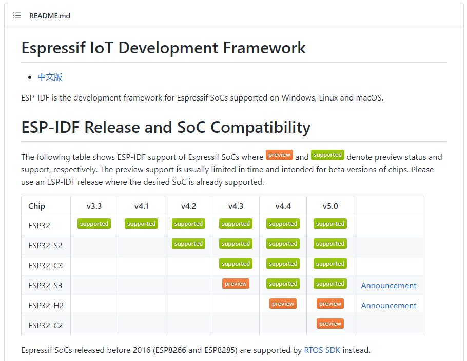
#29 Re: ESP32/ESP8266 » 乐鑫的工具链做得好吗? » 2024-05-11 12:40:35
#30 Re: ESP32/ESP8266 » 乐鑫的工具链做得好吗? » 2024-05-11 11:31:31
#32 Re: 工业芯 匠芯创 » 请问,rgb888和argb8888,区别大吗? » 2024-05-11 10:34:45
#33 Re: 全志 SOC » Linux时间戳到2038年后怎办? » 2024-05-09 19:09:21
#34 Re: 全志 SOC » Linux时间戳到2038年后怎办? » 2024-05-09 11:39:46
#35 全志 SOC » F1C100s启动应用加速:SPI启用DOUT模式(无需启用DMA) » 2024-05-06 19:23:59
- armstrong
- 回复: 1
在spl代码中,用下面的代码替代sys_spi_flash_read函数,就可以最大速度加载app到ram执行。
我的AHB频率是200MHZ,SPI配置为50Mhz(100Mhz不太稳定),下面的代码启用DOUT模式传输,所以理论读取速度是12.5MB/秒。
BROM加载SPL大约150ms,而这段代码加载3MB的app代码仅需250ms,总共400毫秒就能启动3MB的应用程序。
void sys_spi_flash_read_dualout(int addr, void* buf, int count)
{
  uint32_t reg_base = 0x01c05000;
  uint8_t* rxbuf = buf;
  uint8_t tx[5];
  int n, i, c;

  n = 0;
  tx[n++] = 0x3b;   // fast read dual-output
  tx[n++] = (uint8_t)(addr >> 16);
  tx[n++] = (uint8_t)(addr >> 8);
  tx[n++] = (uint8_t)(addr >> 0);
  tx[n++] = 0;
  sys_spi_select();
  write32(reg_base + SPI_MBC, n);
  write32(reg_base + SPI_MTC, n);
  write32(reg_base + SPI_BCC, n);
  for (i = 0; i < n; i++) {
    write8(reg_base + SPI_TXD, tx[i]);
  }
  write32(reg_base + SPI_TCR, read32(reg_base + SPI_TCR) | (1u << 31));
  while (read32(reg_base + SPI_TCR) & (1u << 31));
  write32(reg_base + SPI_FCR, read32(reg_base + SPI_FCR) | 0x80008000u);
  while (count > 0) {
    n = ((count <= 4096) ? count : 4096);
    write32(reg_base + SPI_MBC, n);
    write32(reg_base + SPI_MTC, 0);
    write32(reg_base + SPI_BCC, (1 << 28)); // dual-mode
    write32(reg_base + SPI_TCR, read32(reg_base + SPI_TCR) | (1u << 31));
    for (i = n; i > 0;) {
      // 这里代码看起来很累赘,但是这样却能快速读空RXFIFO!
      if ((c = (read32(reg_base + SPI_FSR) & 0xff)) > 0) {
        i -= c;
        while (c-- > 0) {
          *rxbuf++ = read8(reg_base + SPI_RXD);
        }
      }
    }
    count -= n;
  }
  sys_spi_deselect();
}#36 Re: 全志 SOC » 对于V3s 和 H3 上面 Jtag 的疑问 » 2024-04-30 12:26:38
#37 Re: 工业芯 匠芯创 » 5款Linux桌面环境推荐,你最爱哪个? » 2024-04-29 19:27:44
#38 Re: 工业芯 匠芯创 » 5款Linux桌面环境推荐,你最爱哪个? » 2024-04-29 16:20:36
#39 Re: 全志 SOC » T113-S3 开源双核 FunKey 掌机硬件和系统 » 2024-04-26 11:36:49
#40 Re: 全志 SOC » sunxi-fel uboot到底是怎么样的过程 » 2024-04-25 01:21:27
#41 Re: ESP32/ESP8266 » esp32s3带rgb屏问题 » 2024-04-24 15:06:51
@gaoda
看这个:好多人喜欢开源的LVGL,那就随手加个演示吧,代码在gitee上。
#42 Re: 工业芯 匠芯创 » 工业级芯片之三问三答:可靠性和稳定性是匠芯创产品在软件端的核心指标 » 2024-04-24 14:39:53
文档还是在线的好。官方可以直接修改和增加内容,变更直达用户,不会碎片化。
像乐鑫这样的在线文档系统可以借鉴以下:
https://docs.espressif.com/projects/esp-idf/zh_CN/latest/esp32/index.html
#43 Re: 全志 SOC » 哇酷网友都乐于分享:为大家制作了F1C100s的RTX4+emWin5稳定项目! » 2024-04-24 13:41:37
好多人喜欢开源的LVGL,那就随手加个演示吧,代码在gitee上。
https://gitee.com/xuyao2020/F1C100s_with_Keil_RTX4_emWin5.git
(打开FELinside-LVGL.uvproj项目文件编译得到如下视频演示的bin)
#44 Re: 全志 SOC » f1c200s自制 win10 USB显示屏 » 2024-04-21 18:10:09
#46 Re: 全志 SOC » OOM炸了,DRAM不够,SWAP来凑 » 2024-04-20 11:33:28
#47 Re: 全志 SOC » OOM炸了,DRAM不够,SWAP来凑 » 2024-04-19 11:09:09
#48 Re: 全志 SOC » 模仿stm32标准库风格写的库文件(f1c100s/f1c200s),且已移植了rt-thread、lvgl、fatfs、cherryusb » 2024-04-11 20:51:18
gcc编译环境对于习惯了STM32的老人真是太难了,抽空移植到了keil,有需要的可以联系,目前因boot跟公司其他产品通用,暂时没有开源
https://whycan.com/files/members/8049/微信截图_20240329133209.jpg
大佬,请给我一份你截图中的工程,谢谢!我的邮箱是:26750452@qq.com
#52 Re: RK3288/RK3399/RK1108 » 为什么瑞芯微公开资料这么少呢 » 2024-01-09 22:57:33
#53 Re: RK3288/RK3399/RK1108 » 为什么瑞芯微公开资料这么少呢 » 2024-01-09 17:11:44
#54 Re: RK3288/RK3399/RK1108 » 为什么瑞芯微公开资料这么少呢 » 2024-01-09 17:09:01
#55 Re: RK3288/RK3399/RK1108 » 为什么瑞芯微公开资料这么少呢 » 2024-01-09 17:04:29
#58 Re: 全志 SOC » 模仿stm32标准库风格写的库文件(f1c100s/f1c200s),且已移植了rt-thread、lvgl、fatfs、cherryusb » 2023-12-29 13:33:45
#59 Re: DIY/综合/Arduino/写字机/3D打印机/智能小车/平衡车/四轴飞行/MQTT/物联网 » 花了小半天 搭了个全新版本 eclipse + gcc ... » 2023-12-27 12:24:12
#60 Re: DIY/综合/Arduino/写字机/3D打印机/智能小车/平衡车/四轴飞行/MQTT/物联网 » 花了小半天 搭了个全新版本 eclipse + gcc ... » 2023-12-26 13:54:13
#63 Re: Qt/MSVC/MINGW/C++/MFC/GTK+/Delphi/BCB » 今天一个群友发出来的一段代码(判断两个数相加是否溢出),大家讨论。 » 2023-01-09 19:57:31
#66 Re: DIY/综合/Arduino/写字机/3D打印机/智能小车/平衡车/四轴飞行/MQTT/物联网 » “微软雅黑”不可商用!为了避免日后被字体公司索(qiao)赔(zha), 请尽快改用商业免费字体. » 2022-11-19 00:03:22
#68 Re: 全志 SOC » 最近做的F1C100S运行LVGL8的效果视频,提供源代码,开源硬件,方便需要的同学。 » 2022-11-07 09:55:24
楼主,这个emWin5.32版的ARM9版库是从哪里抠出来的呢?NXP?
#69 Re: 全志 SOC » 为什么看到大家用F1C100s比用V3s的多呢? » 2022-10-21 09:08:18
#70 Re: 全志 SOC » 随便水一贴,电阻触摸屏校正 » 2022-07-07 22:08:28
#72 Re: 全志 SOC » 发现一个有意思的东西,4.3寸触摸屏,用的F1C200S » 2022-04-28 16:58:39
#73 Re: RISC-V » 自制小型操作系统内核nxos支持risc-v架构64位系统 » 2022-04-13 08:24:40
#74 Re: DIY/综合/Arduino/写字机/3D打印机/智能小车/平衡车/四轴飞行/MQTT/物联网 » 启明云端分享| 采用 B to B设计的RK3399核心板【邮票孔,支持4K、H.265 硬解码】 » 2022-04-10 21:39:03
#75 Re: DIY/综合/Arduino/写字机/3D打印机/智能小车/平衡车/四轴飞行/MQTT/物联网 » 启明云端分享| 采用 B to B设计的RK3399核心板【邮票孔,支持4K、H.265 硬解码】 » 2022-04-10 21:37:31
#76 Re: 全志 SOC » F1C200S显示问题 » 2022-04-02 16:53:47
#79 Re: Cortex M0/M3/M4/M7 » 一个GD32的CAN外设硬件bug » 2022-03-12 19:12:58
#81 Re: 技术人生/软件使用技巧/破解经验/技术吐槽/灌水 » 有没有人想创业? » 2022-01-21 14:34:04
#82 Re: 全志 SOC » f1c100s跑rttt+lvgl画面有撕裂感 » 2021-12-16 17:31:16
lvgl\examples\porting\lv_port_disp_template.c
void lv_port_disp_init(void)
{
    /*-------------------------
     * Initialize your display
     * -----------------------*/
    disp_init();

    /*-----------------------------
     * Create a buffer for drawing
     *----------------------------*/

    /**
     * LVGL requires a buffer where it internally draws the widgets.
     * Later this buffer will passed to your display driver's `flush_cb` to copy its content to your display.
     * The buffer has to be greater than 1 display row
     *
     * There are 3 buffering configurations:
     * 1. Create ONE buffer:
     *      LVGL will draw the display's content here and writes it to your display
     *
     * 2. Create TWO buffer:
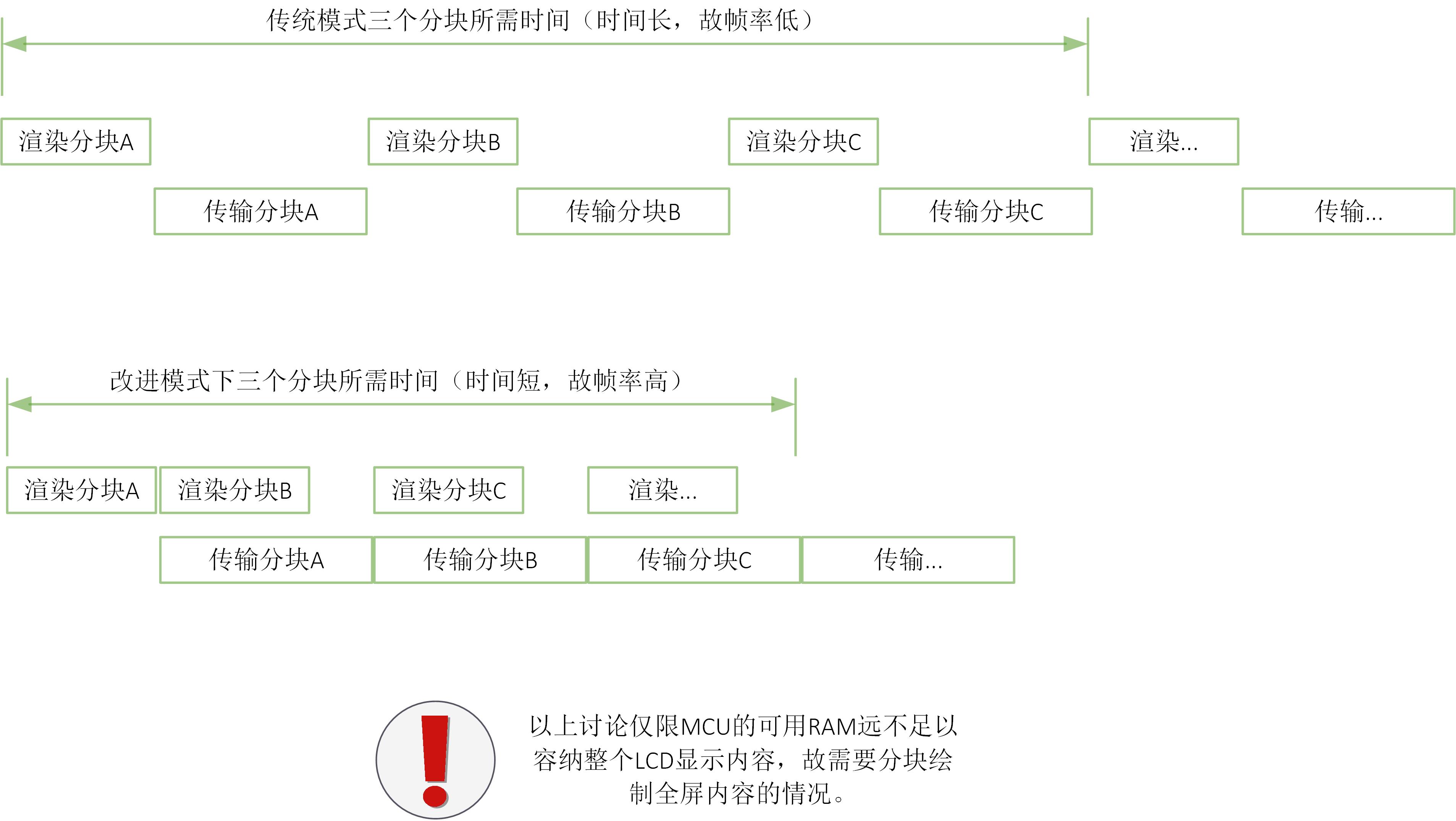
     *      LVGL will draw the display's content to a buffer and writes it your display.
     *      You should use DMA to write the buffer's content to the display.
     *      It will enable LVGL to draw the next part of the screen to the other buffer while
     *      the data is being sent form the first buffer. It makes rendering and flushing parallel.
     *
     * 3. Double buffering
     *      Set 2 screens sized buffers and set disp_drv.full_refresh = 1.
     *      This way LVGL will always provide the whole rendered screen in `flush_cb`
     *      and you only need to change the frame buffer's address.
     */

    /* Example for 1) */
    static lv_disp_draw_buf_t draw_buf_dsc_1;
    static lv_color_t buf_1[MY_DISP_HOR_RES * 10];                          /*A buffer for 10 rows*/
    lv_disp_draw_buf_init(&draw_buf_dsc_1, buf_1, NULL, MY_DISP_HOR_RES * 10);   /*Initialize the display buffer*/

    /* Example for 2) */
    static lv_disp_draw_buf_t draw_buf_dsc_2;
    static lv_color_t buf_2_1[MY_DISP_HOR_RES * 10];                        /*A buffer for 10 rows*/
    static lv_color_t buf_2_1[MY_DISP_HOR_RES * 10];                        /*An other buffer for 10 rows*/
    lv_disp_draw_buf_init(&draw_buf_dsc_2, buf_2_1, buf_2_1, MY_DISP_HOR_RES * 10);   /*Initialize the display buffer*/

    /* Example for 3) also set disp_drv.full_refresh = 1 below*/
    static lv_disp_draw_buf_t draw_buf_dsc_3;
    static lv_color_t buf_3_1[MY_DISP_HOR_RES * MY_DISP_VER_RES];            /*A screen sized buffer*/
    static lv_color_t buf_3_1[MY_DISP_HOR_RES * MY_DISP_VER_RES];            /*An other screen sized buffer*/
    lv_disp_draw_buf_init(&draw_buf_dsc_3, buf_3_1, buf_3_2, MY_DISP_VER_RES * LV_VER_RES_MAX);   /*Initialize the display buffer*/

    /*-----------------------------------
     * Register the display in LVGL
     *----------------------------------*/

    static lv_disp_drv_t disp_drv;                         /*Descriptor of a display driver*/
    lv_disp_drv_init(&disp_drv);                    /*Basic initialization*/

    /*Set up the functions to access to your display*/

    /*Set the resolution of the display*/
    disp_drv.hor_res = 480;
    disp_drv.ver_res = 320;

    /*Used to copy the buffer's content to the display*/
    disp_drv.flush_cb = disp_flush;

    /*Set a display buffer*/
    disp_drv.draw_buf = &draw_buf_dsc_1;

    /*Required for Example 3)*/
    //disp_drv.full_refresh = 1

    /* Fill a memory array with a color if you have GPU.
     * Note that, in lv_conf.h you can enable GPUs that has built-in support in LVGL.
     * But if you have a different GPU you can use with this callback.*/
    //disp_drv.gpu_fill_cb = gpu_fill;

    /*Finally register the driver*/
    lv_disp_drv_register(&disp_drv);
}#83 Re: 全志 SOC » f1c100s跑rttt+lvgl画面有撕裂感 » 2021-12-16 17:22:57
#84 Re: 全志 SOC » f1c100s跑rttt+lvgl画面有撕裂感 » 2021-12-16 17:16:51
#85 Re: 全志 SOC » f1c100s性能和stm32哪个型号性能差不多啊 » 2021-12-15 12:28:30
#87 Re: 全志 SOC » 网站需要改革,放开文件下载权限(不需要与积分挂钩) » 2021-12-09 19:01:54
#88 Re: 全志 SOC » 网站需要改革,放开文件下载权限(不需要与积分挂钩) » 2021-12-09 17:02:52
#89 Re: 全志 SOC » 网站需要改革,放开文件下载权限(不需要与积分挂钩) » 2021-12-09 17:00:25
#91 Re: 全志 SOC » Debian 9.9 (stretch) 文件系统制作 » 2021-12-06 10:20:17
#92 Re: 全志 SOC » 开源一个6000行的2D矢量图形库libcg,零依赖,API接口类似cairo,在某些场景可以代替cairo,特别适合裸奔场景。 » 2021-12-04 22:52:05
#93 Re: PikaPython(嵌入式Python引擎) » 【pikascript】超轻量级的跨平台嵌入式Python解释器,可以在STM32G030等小资源MCU运行 » 2021-12-02 16:30:28
#94 Re: 计算机图形/GUI/RTOS/FileSystem/OpenGL/DirectX/SDL2 » 请教大家,fb RGB565 color key与ARGB1555问题 » 2021-11-22 20:09:47
#95 Re: 计算机图形/GUI/RTOS/FileSystem/OpenGL/DirectX/SDL2 » 请教大家,fb RGB565 color key与ARGB1555问题 » 2021-11-22 16:07:43
#96 Re: 全志 SOC » f1c100s+lvgl 渐变色显示效果那么差的吗, » 2021-11-22 15:20:58
#97 Re: 全志 SOC » f1c100s+lvgl 渐变色显示效果那么差的吗, » 2021-11-22 12:36:23
#103 Re: RISC-V » 联盛德W806 MCU使用LVGLv8 刷8bit ST7789屏 » 2021-11-15 15:48:28
#104 Re: 全志 SOC » 小白自制Linux开发板(F1C200s)整理系列,持续更新中 » 2021-11-10 15:10:43
#105 Re: 全志 SOC » XFEL已支持spi nand flash烧写 » 2021-11-03 10:54:59
#106 Re: 全志 SOC » XFEL已支持spi nand flash烧写 » 2021-11-02 09:50:24
#107 Re: Cortex M0/M3/M4/M7 » GD32F1x0的非零等待闪存运行速度测试 » 2021-10-26 11:30:58
#108 Re: Cortex M0/M3/M4/M7 » GD32F1x0的非零等待闪存运行速度测试 » 2021-10-26 11:30:01
#109 Re: Cortex M0/M3/M4/M7 » GD32F1x0的非零等待闪存运行速度测试 » 2021-10-26 11:27:02
#110 Re: BLDC电机驱动 » 这板块人好少,想问问大家现在对变频器开发的看法。 » 2021-10-25 19:18:43
#113 Re: 全志 SOC » debian10自动添加了屏幕终端? » 2021-10-05 20:43:12
#115 Re: ESP32/ESP8266 » ESP_MASTER 开源一个地表最强ESP32-CAM » 2021-09-09 17:15:21
#116 Re: 全志 SOC » f1c200s(tiny200) linux+emwin稳定运行 » 2021-08-16 13:54:31
#117 Re: Nuvoton N32905/N32926/NUC972/N9H20/N9H26/N9H30 » 请问一下NUC972上跑linux应用串口响应时间最短为时间为多少?? » 2021-07-20 13:18:13
#118 Re: 全志 SOC » 乡下老鼠与城里老鼠交了个朋友,我来试试PWM直驱喇叭 » 2021-07-15 12:18:03
#119 Re: 全志 SOC » 乡下老鼠与城里老鼠交了个朋友,我来试试PWM直驱喇叭 » 2021-07-14 23:03:12
#120 Re: 全志 SOC » 利用xfel及mkz工具实现一机一镜像量产方案 » 2021-06-28 11:53:49
#121 Re: 全志 SOC » 发现一个各种体系架构windows平台GNU/GCC工具链的网站,包括 RISC-V,跑个xboot的d1-baremetal.bin试一试 » 2021-06-21 18:27:16
#122 Re: 全志 SOC » f1c200s(tiny200) linux+emwin稳定运行 » 2021-06-17 19:12:58
#124 Re: 全志 SOC » V3S 成功运行dotnet core 5.0 » 2021-05-25 22:10:06
#125 Re: 全志 SOC » VGA module & baremetal programming » 2021-05-25 08:56:45
#126 Re: RISC-V » 神奇的x0寄存器 ---- 说说RISC-V的x0寄存器(转) » 2021-05-14 13:25:09
#127 Re: 站务公告/网站建设 » 说话都时刻有人监控了?恐慌到如此地步? » 2021-05-07 14:36:16
#128 Re: 全志 SOC » 用F1C100S开发了一个项目,原始技术实现,裸奔XUI GUI框架 » 2021-04-25 11:57:54
#129 Re: DIY/综合/Arduino/写字机/3D打印机/智能小车/平衡车/四轴飞行/MQTT/物联网 » Linux串口实时接收二进制数据流的探讨 » 2021-03-26 17:08:20
#130 Re: 计算机图形/GUI/RTOS/FileSystem/OpenGL/DirectX/SDL2 » ucgui3.98源码【转】 » 2021-03-14 14:27:03
uc/gui-3.98在15年前就网上轻易能下载到了,而且没有内存设备和抗锯齿字体支持的。对目前来说已经太古老了。
还是用这个吧,emWin5.06源代码,组件更多代码更新:
emWin506-Src.7z
#131 Re: 计算机图形/GUI/RTOS/FileSystem/OpenGL/DirectX/SDL2 » 不明白rtt的这个for迭代是如何实现的。 » 2021-03-14 10:33:59
#132 Re: 全志 SOC » v3s 怎么做一个离线识别功能? » 2021-03-09 10:11:33
#133 Re: 技术人生/软件使用技巧/破解经验/技术吐槽/灌水 » 技术人的误区 » 2021-03-08 19:49:58
#134 Re: 技术人生/软件使用技巧/破解经验/技术吐槽/灌水 » 技术人的误区 » 2021-03-08 19:22:31
#135 Re: 全志 SOC » 想用F1C500S 替代F1C100S 跑裸机,发现跑不起来。 » 2021-03-04 11:52:41
#136 Re: 全志 SOC » F1c100S 的性能到底如何?怎么看天梯图ARM9只相当于M0的性能 » 2021-03-03 09:04:14
#138 Re: DIY/综合/Arduino/写字机/3D打印机/智能小车/平衡车/四轴飞行/MQTT/物联网 » 嫌全字库ttf文件太肥的朋友,可以进来看看了,按需剪裁, 减肥/瘦身/不留赘肉 » 2021-02-08 15:40:11
#141 Re: 全志 SOC » 这果然很linux » 2021-01-27 20:18:42
#144 Re: 全志 SOC » 新作F1C200S,打算百分之百开源,给大家的新年礼物。 » 2021-01-23 20:34:41
#145 Re: 全志 SOC » 求助:f1c100s vscode下驱动编写 老是编译不过, » 2021-01-21 18:47:36
#146 Re: 计算机图形/GUI/RTOS/FileSystem/OpenGL/DirectX/SDL2 » 试一试 直接用 win32 api 运行 OpenGL 程序 » 2021-01-18 18:53:48
搬出我多年前的收藏给楼主助威吧,NEHE OpenGL 教学例程,例程个个精美:
nehegl.zip
#148 Re: 计算机图形/GUI/RTOS/FileSystem/OpenGL/DirectX/SDL2 » RT-Thread Smart移植初体验有奖活动 » 2021-01-12 22:39:41
#149 Re: 技术人生/软件使用技巧/破解经验/技术吐槽/灌水 » 从今天起我要加倍重视自己的价值 » 2021-01-09 16:03:27
#150 Re: 全志 SOC » 嵌入式linux是做驱动好还是应用好? » 2021-01-05 11:00:30
#151 Re: 全志 SOC » [慢更]小白探索如何使用V3s播放音乐 » 2021-01-04 19:31:42
#155 Re: ESP32/ESP8266 » esp32s2移植VSF,顺便跑起USB主机协议栈 » 2020-12-24 15:14:15
#156 Re: ESP32/ESP8266 » esp32s2移植VSF,顺便跑起USB主机协议栈 » 2020-12-24 15:06:47
#157 Re: ESP32/ESP8266 » esp32s2移植VSF,顺便跑起USB主机协议栈 » 2020-12-24 15:05:42
#158 Re: 全志 SOC » F1C100S U盘速度 » 2020-12-17 18:46:41
#159 Re: 计算机图形/GUI/RTOS/FileSystem/OpenGL/DirectX/SDL2 » 研究了1天,终于搞清楚如何在LVGL上显示GBK字串,分享一下让大家少踩坑 » 2020-12-16 20:23:41
#161 Re: DIY/综合/Arduino/写字机/3D打印机/智能小车/平衡车/四轴飞行/MQTT/物联网 » 关于Ubuntu 18.04下编译 SSD202D(卖家给的SDK)的文件无法通过uboot更新到nand上的问题 » 2020-12-08 20:23:57
#162 Re: 全志 SOC » 有没有大佬有SSD201 EVK的原理图??有的大佬能分享一吓吗? » 2020-12-08 18:41:06
#164 Re: DIY/综合/Arduino/写字机/3D打印机/智能小车/平衡车/四轴飞行/MQTT/物联网 » 一个跨越5年的业余项目LineWatch » 2020-10-26 16:15:40
#165 Re: 计算机图形/GUI/RTOS/FileSystem/OpenGL/DirectX/SDL2 » 这种数码管字体 littlevgl / lvgl 计时器/倒计时器 界面如何? » 2020-10-26 13:52:18
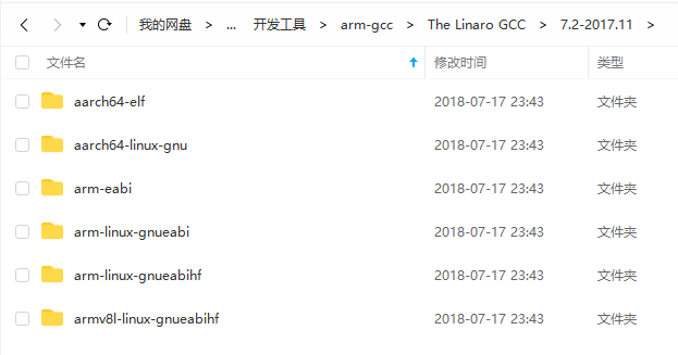
#167 Re: 全志 SOC » codesourcery的gcc toolchain停更了,linaro的gcc工具链没有arm926ej-s/armv5te的版本 » 2020-10-09 12:05:23
https://developer.arm.com/tools-and-software/open-source-software/developer-tools/gnu-toolchain
以上A配置和RM配置的都支持armv5te,内置none-eabi的newlib库用于生成裸机程序。
能编译linux内核和uboot,但不能编译linux应用程序和rootfs工具集。
#168 Re: Php/Nodejs/Web/HTML5/Javascript/微信开发/Python » 请问公司架设apache2网页服务器,只允许下载pdf文件,其他文件一律禁止,conf文件应该如何配置? » 2020-09-19 17:00:25
#169 Re: 全志 SOC » 能裸机调用GPU吗? » 2020-09-18 16:47:13
#170 Re: Php/Nodejs/Web/HTML5/Javascript/微信开发/Python » 微信支付成功后, 这个服务器通知本机(notify)协议, 感觉不合理 » 2020-09-18 08:06:18
#171 Re: 全志 SOC » F1C100S Dram 出错 » 2020-09-09 10:48:48
#172 Re: Php/Nodejs/Web/HTML5/Javascript/微信开发/Python » 跟上时代,记录一下刚刚看视频学会的 php + 微信公众号开发 » 2020-08-31 21:22:50
深表赞同!
不久的新闻有人微信被封,付出了生命的代价,还不放弃微信。不要过渡依赖微信,要是经营多年的公众号哪天被封搞个鸡儿。
什么平台都不要过渡依赖。那年渣浪被整改,清空了所有用户网盘存的东西,我多年在渣浪积累的无形资产文档都没了。
网友存档
https://info.williamlong.info/2016/04/blog-post_25.html
不要徒方便把自己的无形资产交给平台,搞公众号不如学哇酷站长搞个网站,牢牢拽在自己手里的无形资产。
#173 Re: 全志 SOC » 为了V3S不吃灰,移植NES游戏 » 2020-08-20 21:21:03
#175 Re: 全志 SOC » f1c200s(tiny200) linux+emwin稳定运行 » 2020-06-28 08:40:24
#178 Re: 全志 SOC » 荔枝派Nano联网???? » 2020-06-17 08:33:34
https://whycan.cn/files/members/4270/22_20200617-0127.png
为什么明明在里面也不能。颜色有什么含义吗
是不是应该这样“./iwlist”
#179 Re: 全志 SOC » 基于RTThread的F1C100s开发(带boot启动+硬件多图层+硬件游标+LVGL+SDIO) » 2020-06-15 19:04:30
执行mksunxi.exe 时候 报出找不到MSVCR120D.dll,找了个msvcr120d.dll和mksunxi.exe放到一块,弄好了。。。。。
换个版本的mksunxi.exe吧,你这个不是mingw编译的;mingw编译的不会依赖这个dll。
用这个:
mksunxi.7z
#182 Re: 计算机图形/GUI/RTOS/FileSystem/OpenGL/DirectX/SDL2 » 在emWin中,如果摁住一个button不释放,同时再摁屏幕其他区域然后释放时,发现摁住的button被执行。 » 2020-06-09 21:16:56
#183 Re: 全志 SOC » f1c100s spi不能使用burst模式??? » 2020-06-04 12:50:18
#184 Re: 全志 SOC » f1c100s spi不能使用burst模式??? » 2020-06-03 10:09:06
可以用类似我开头那种做法,完全可以一次性读完,不需要64字节分组收发嘛,就是不知道为何不对:(
试试看这样写行不?
void sys_spi_flash_read(int addr, void* buf, int count)
{
    uint8_t *p = (uint8_t *)buf;

    sys_spi_select();

    SPI0->MBC = 4;
    SPI0->MTC = 4;
    SPI0->BCC = 4;
    SPI0->TXD = 0x03 | util_rev(addr);
    SPI0->TCR |= SPI_TCR_XCH;
    while (SPI0->FSR & 0xff) < 4);
    read8((uint32_t)&SPI0->RXD);
    read8((uint32_t)&SPI0->RXD);
    read8((uint32_t)&SPI0->RXD);
    read8((uint32_t)&SPI0->RXD);

    SPI0->MBC = count;
    SPI0->MTC = 0;
    SPI0->BCC = 0;
    SPI0->TCR |= SPI_TCR_XCH;
    while (count > 0) {
      if((SPI0->FSR & 0xFF) > 0)
      {
          *p++ = read8((uint32_t)&SPI0->RXD);
          count -= 1;
      }
    }

    sys_spi_deselect();
}#185 Re: 全志 SOC » f1c100s spi不能使用burst模式??? » 2020-06-02 17:28:37
读FIFO时,SPI是停止的;这里的确浪费了传输机会。
不过,count循环中并不会重复发送4字节命令和地址,因为在读取数据时,sys_spi_transfer函数的txbuf参数是NULL,所以循环内的sys_spi_write_txbuf函数会立即返回,没有实际数据发送的。
https://whycan.cn/files/members/1592/2020-05-29_100040.png
我还没用逻辑分析仪测量过。要把这些时间省下来,就只能靠DMA了。
#186 Re: 全志 SOC » f1c100s spi不能使用burst模式??? » 2020-05-29 12:06:42
#187 Re: 全志 SOC » f1c100s spi不能使用burst模式??? » 2020-05-29 10:07:54
感谢Armstrong的亲临指导,我今天再去测试一下原来代码spi读写的情况,spi频率太高了示波器太烂丢脉冲,不过应该可以发现问题的
原来的代码相当于将总的数据收发切割成64字节成组收发,并且读取rxfifo时候还是spi停止的
64+4字节收发->读rxfiofo,然后再重复这个过程
读FIFO时,SPI是停止的;这里的确浪费了传输机会。
不过,count循环中并不会重复发送4字节命令和地址,因为在读取数据时,sys_spi_transfer函数的txbuf参数是NULL,所以循环内的sys_spi_write_txbuf函数会立即返回,没有实际数据发送的。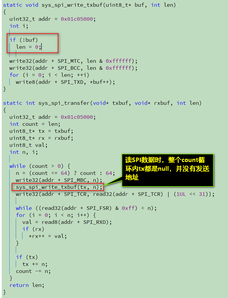
上层的flash读函数实际上这样解释:
static int sys_spi_write_then_read(void* txbuf, int txlen, void* rxbuf, int rxlen)
{
  // 发送命令+地址
  if (sys_spi_transfer(txbuf, NULL, txlen) != txlen)
    return -1;
  // 连续接收纯数据
  if (sys_spi_transfer(NULL, rxbuf, rxlen) != rxlen)
    return -1;
  return 0;
}#189 Re: 全志 SOC » f1c100s spi不能使用burst模式??? » 2020-05-28 21:32:20
#190 Re: 技术人生/软件使用技巧/破解经验/技术吐槽/灌水 » 求版主开放下载权限 » 2020-05-27 14:34:17
#199 Re: 计算机图形/GUI/RTOS/FileSystem/OpenGL/DirectX/SDL2 » 谁有emwin的arm9 gcc linux版本的静态库? » 2020-05-13 18:23:05
#200 Re: 计算机图形/GUI/RTOS/FileSystem/OpenGL/DirectX/SDL2 » 谁有emwin的arm9 gcc linux版本的静态库? » 2020-05-13 18:06:34
用链接器的redirect功能,把库里的某几个函数旁路掉,自己写函数代替。
或者索性自己写个GUI_DEVICE_API,别用内置<GUIDRV_Lin.h>文件里的驱动就行。
自定义驱动形式如下,有模板的,不难实现,针对内存操作的更简单:
const GUI_DEVICE_API GUIDRV_Template_API = {
  //
  // Data
  //
  DEVICE_CLASS_DRIVER,
  //
  // Drawing functions
  //
  _DrawBitmap,
  _DrawHLine,
  _DrawVLine,
  _FillRect,
  _GetPixelIndex,
  _SetPixelIndex,
  _XorPixel,
  //
  // Set origin
  //
  _SetOrg,
  //
  // Request information
  //
  _GetDevFunc,
  _GetDevProp,
  _GetDevData,
  _GetRect,
};- 首页
- » 搜索
- » armstrong 发表的帖子
太原小智科技有限责任公司 - 东莞哇酷科技有限公司联合开发
