- 首页
- » 搜索
- » HongSang 发表的帖子
页次: 1
#3 Re: 全志 SOC » ①用 xfel.exe 初始化 F1C100s DDR, ②把可执行文件下载到DDR ③执行程序 » 2022-01-18 15:14:08
@哇酷小二
OK!!! 这似乎是解决问题的关键所在 我buildroot编译完固件也有看到这样的信息
INFO: cmd: "find '/home/linux/mango/buildroot-tiny200/output/build/genimage.tmp/root' -depth -type d -printf '%P\0' | xargs -0 -I {} touch -r '/tmp/tmp.pBLtte62uT/{}' '/home/linux/mango/buildroot-tiny200/output/build/genimage.tmp/root/{}'" (stderr):
INFO: cmd: "mkdir -p "/home/linux/mango/buildroot-tiny200/output/images"" (stderr):
INFO: flash(sysimage-nor.img): writing image partition 'u-boot' (0x80000@0x0)
INFO: flash(sysimage-nor.img): writing image partition 'splash' (0x80000@0x80000)
INFO: flash(sysimage-nor.img): writing image partition 'kernel' (0x500000@0x100000)
INFO: flash(sysimage-nor.img): writing image partition 'rom' (0xa00000@0x600000)
board/allwinner/generic/genimage-nand.cfg:33: no sub-section title/index for 'config'
INFO: cmd: "mkdir -p "/home/linux/mango/buildroot-tiny200/output/build/genimage.tmp"" (stderr):
INFO: cmd: "rm -rf "/home/linux/mango/buildroot-tiny200/output/build/genimage.tmp"/*" (stderr):
INFO: cmd: "mkdir -p "/home/linux/mango/buildroot-tiny200/output/build/genimage.tmp"" (stderr):
INFO: cmd: "cp -a "/tmp/tmp.1SJGd7hvCu" "/home/linux/mango/buildroot-tiny200/output/build/genimage.tmp/root"" (stderr):
INFO: cmd: "find '/home/linux/mango/buildroot-tiny200/output/build/genimage.tmp/root' -depth -type d -printf '%P\0' | xargs -0 -I {} touch -r '/tmp/tmp.1SJGd7hvCu/{}' '/home/linux/mango/buildroot-tiny200/output/build/genimage.tmp/root/{}'" (stderr):
INFO: cmd: "mkdir -p "/home/linux/mango/buildroot-tiny200/output/images"" (stderr):
INFO: flash(sysimage-nand.img): writing image partition 'u-boot' (0x80000@0x0)
INFO: flash(sysimage-nand.img): writing image partition 'splash' (0x80000@0x80000)
INFO: flash(sysimage-nand.img): writing image partition 'kernel' (0x500000@0x100000)
INFO: flash(sysimage-nand.img): writing image partition 'rom' (0x7a00000@0x600000)
我的执行指令是这样的
xfel  spinand
xfel spinand erase 0x000000 134217728
 xfel spinand write 0x000000 u-boot-sunxi-with-nand-spl.bin
 xfel spinand write 0x80000 splash.bmp
 xfel spinand write 0x100000 kernel.itb
 xfel spinand write 0x600000 rootfs.squashfs
晕哥yyds!xfel yyds!
之前是换成120nand想用芒果派r3的固件但是在fel->dfu分区的时候我这里出了点小问题,幸亏有了xboot的xfel!
#4 Re: 全志 SOC » ①用 xfel.exe 初始化 F1C100s DDR, ②把可执行文件下载到DDR ③执行程序 » 2022-01-18 11:06:16
哇酷小二 wrote:
@HongSang
建议把dtb和zImage读到内存之后,再校验一次crc32,确认数据没有问题。
	partitions {
			compatible = "fixed-partitions";
			#address-cells = <1>;
			#size-cells = <1>;

			partition@0 {
				label = "u-boot";
				reg = <0x000000 0x100000>;
				read-only;
			};

			partition@1 {
				label = "kernel";
				reg = <0x100000 0x500000>;
				read-only;
			};

			partition@2 {
				label = "rom";
				reg = <0x600000 0x2a00000>;
				read-only;
			};

			partition@3 {
				label = "vendor";
				reg = <0x3000000 0x1000000>;
			};

			partition@4 {
				label = "overlay";
				reg = <0x4000000 0x3000000>;
			};
		};
现在问题是我不知道如何将dtb和rootfs读进nand分区,那么读到ddr分区也不知道它的<address>, 这个分区在设备树中这样定义的
#5 Re: 全志 SOC » ①用 xfel.exe 初始化 F1C100s DDR, ②把可执行文件下载到DDR ③执行程序 » 2022-01-18 10:08:05
哇酷小二 wrote:
现在烧uboot能不能跑起来?
可以跑起来的 log ↓:
U-Boot 2020.07 (Jan 18 2022 - 09:53:19 +0800) Allwinner Technology

CPU:   Allwinner F Series (SUNIV)
Model: Allwinner F1C100s Generic Device
DRAM:  64 MiB
MMC:   mmc@1c0f000: 0, mmc@1c10000: 1
Setting up a 480x480 lcd console (overscan 0x0)
In:    serial
Out:   serial
Err:   serial
Allwinner mUSB OTG (Peripheral)
Hit any key to stop autoboot:  0
Card did not respond to voltage select!
Card did not respond to voltage select!
unrecognized JEDEC id bytes: ff, c8, f1
Failed to initialize SPI flash at 0:0 (error -2)
List of MTD devices:
* spi-nand0
  - device: spi-nand@1
  - parent: spi@1c05000
  - driver: spi_nand
  - type: NAND flash
  - block size: 0x20000 bytes
  - min I/O: 0x800 bytes
  - OOB size: 64 bytes
  - OOB available: 31 bytes
  - 0x000000000000-0x000008000000 : "spi-nand0"
=========================
Boot Device: spi
Boot Slot 0: empty
Boot Slot 1: spi-nand
=========================
Reading 524288 byte(s) (256 page(s)) at offset 0x00080000
Unknown command 'bmp' - try 'help'
gpio: pin 134 (gpio 134) value is 1
DFU waiting on SPI-NAND...
musb-hdrc: peripheral reset irq lost!
Booting from SPI-NAND...
Reading 5242880 byte(s) (2560 page(s)) at offset 0x00100000
Wrong Image Format for bootm command
ERROR: can't get kernel image!
DFU waiting on SPI-NAND...
烧写zImage后
U-Boot SPL 2020.07 (Jan 18 2022 - 09:53:19 +0800)
board init start
DRAM: 64 MiB
board init start
Start GPIO Testing
Trying to boot from MMC1
Card did not respond to voltage select!
spl: mmc init failed with error: -95
Trying to boot from MMC2
Card did not respond to voltage select!
spl: mmc init failed with error: -95
Trying to boot from sunxi SPI
SPI-NAND: GigaDevice GD5F1GQ4UAYIG
SPI-NAND: U-Boot address: 53248

U-Boot 2020.07 (Jan 18 2022 - 09:53:19 +0800) Allwinner Technology

CPU:   Allwinner F Series (SUNIV)
Model: Allwinner F1C100s Generic Device
DRAM:  64 MiB
MMC:   mmc@1c0f000: 0, mmc@1c10000: 1
Setting up a 480x480 lcd console (overscan 0x0)
In:    serial
Out:   serial
Err:   serial
Allwinner mUSB OTG (Peripheral)
Hit any key to stop autoboot:  0
=> FU waiting on SPI-NAND...
Unknown command 'FU' - try 'help'
=>#6 Re: 全志 SOC » ①用 xfel.exe 初始化 F1C100s DDR, ②把可执行文件下载到DDR ③执行程序 » 2022-01-17 18:43:52
	partitions {
			compatible = "fixed-partitions";
			#address-cells = <1>;
			#size-cells = <1>;

			partition@0 {
				label = "u-boot";
				reg = <0x000000 0x100000>;
				read-only;
			};

			partition@1 {
				label = "kernel";
				reg = <0x100000 0x500000>;
				read-only;
			};

			partition@2 {
				label = "rom";
				reg = <0x600000 0x2a00000>;
				read-only;
			};

			partition@3 {
				label = "vendor";
				reg = <0x3000000 0x1000000>;
			};

			partition@4 {
				label = "overlay";
				reg = <0x4000000 0x3000000>;
			};
		};
晕哥请问 芒果派r3 是这样分区的 后面的设备树和文件系统该怎么填地址呢 好像是用的overlay分区
xfel spinand write 0x000000 uboot.bin
xfel spinand write 0x100000 zImage
还有我这里如果有一个镜像文件system-nand.img,已经包含了uboot、kernel、dtb、rootfs 该怎么烧写呢
xfel spinand write 0x000000 system-nand.img 试过了没有用 只有uboot能起来
#7 Re: 全志 SOC » XFEL已支持spi nand flash烧写 » 2022-01-17 17:23:24
thank you very much
#8 Re: 全志 SOC » XFEL已支持spi nand flash烧写 » 2022-01-17 16:30:24
#9 Re: 全志 SOC » ①用 xfel.exe 初始化 F1C100s DDR, ②把可执行文件下载到DDR ③执行程序 » 2022-01-17 15:26:05
@哇酷小二
晕哥我再请假下 这里的<address>是指烧入分区的起始地址吗?就是在如下设备树中的定义的 reg?
例如烧写uboot xfel spinor write 0x000000 u-boot.bin
烧写dtb xfel spinor write 0x100000 .dtb
烧写zImage xfel spinor write 0x110000 zIamge
            partition@0 {
                label = "u-boot";
                reg = <0x000000 0x100000>;
                read-only;
            };

            partition@100000 {
                label = "dtb";
                reg = <0x100000 0x10000>;
                read-only;
            };

            partition@110000 {
                label = "kernel";
                reg = <0x110000 0x400000>;
                read-only;
            };

            partition@510000 {
                label = "rootfs";
                reg = <0x510000 0xAF0000>;
				//reg = <0x510000 0xBF0000>;
            };
<length>是指文件的大小吗?
#10 Re: 全志 SOC » XFEL已支持spi nand flash烧写 » 2022-01-17 15:14:54
#14 Re: 全志 SOC » 求助 F1C100s使用 gpio模拟spi 驱动ST7701s spi9bit+rgb屏的问题 屏幕不亮 逻辑分析仪波形不对 » 2021-11-04 09:24:11
哇酷小二 wrote:
现在可以显示了吗?
不行 颜色显示不对,另外屏幕有些花边 由panel生成的/dev/fb1可以控制
cat /dev/urandom > /dev/fb1
cat /dev/zero > /dev/fb1
另外uboot bootargs设置tty0让屏幕显示系统开机 屏幕没有任何显示
uboot
=> print bootargs
bootargs=console=tty0 console=ttyS0,115200 panic=5 rootwait root=/dev/mtdblock3 rw rootfstype=jffs2
/etc/inittab
# Put a getty on the serial port
ttyS0::respawn:/sbin/getty -L  ttyS0 115200 vt100 # GENERIC_SERIAL
tty0::respawn:-/bin/sh
/dev/console::respawn:-/bin/sh#15 Re: 全志 SOC » F1C100s如何初始化LCD引脚 ?24bit如何修改成18bit。RGB666如何修改成565.。。。。 » 2021-11-03 19:20:01
达克罗德 wrote:
我记得是uboot配置的,Linux没有去配置
linux源码里我配置了/driver/gpu/drm/panel/panel-simple.c一个屏幕,并且设备树里panel节点引用了这个屏幕.但是现在屏幕颜色不对 感觉颜色还是888
linux里实在找不到修改的地方了,在uboot menuconfig配置的时候看到了ARM architecture ‣ Enable graphical uboot console on HDMI, LCD or VGA这里设置了x:800,y:480,depth:18,pclk_khz:33000,le:87,ri:40,up:31,lo:13,hs:1,vs:1,sync:3,vmode:0这一行参数,感觉这里屏幕的rgb初始化是在uboot完成的。https://blog.csdn.net/b7376811/article/details/112525402
请问您在uboot哪里配置rgb相关的参数
#16 Re: 全志 SOC » f1c100s调起4.3寸800x480液晶屏 » 2021-11-03 19:08:44
#17 Re: 全志 SOC » F1c100s是否成功启动SPI屏(st7789v)!? » 2021-11-03 09:38:05
#18 全志 SOC » F1C100s如何初始化LCD引脚 ?24bit如何修改成18bit。RGB666如何修改成565.。。。。 » 2021-11-03 09:35:57
- HongSang
- 回复: 7
1、设备树里的LCD这组引脚是如何传参的,定义的顺序是什么
	lcd_rgb565_pins: lcd-rgb565-pins {
				pins = "PD0","PD1", "PD2", "PD3", "PD4",
				       "PD5", "PD6", "PD7", "PD8", "PD9",
				       "PD10", "PD11",  "PD12","PD13", "PD14",
				       "PD15", "PD16", "PD17", "PD18", "PD19",
				       "PD20", "PD21";
				function = "lcd";
			};
2、RGB的初始化是否需要uboot里面配置?和设备树无关
#19 Re: 全志 SOC » f1c100s驱动st7789v的问题 » 2021-11-03 09:22:10
#21 Re: 全志 SOC » 求助 F1C100s使用 gpio模拟spi 驱动ST7701s spi9bit+rgb屏的问题 屏幕不亮 逻辑分析仪波形不对 » 2021-11-02 16:15:43
哇酷小二 wrote:
@HongSang
对, 时序就是 panel-simple 里面配置,参考 aodzip 那个 sdk即可,示波器检测到 PCLK, VSYNC, HSYNC 理论上屏幕显示就稳了。
晕哥,对panel的配置是否需要在uboot里配置?看到了如下链接
新版本主线内核上的并行RGB LCD适配(解决启动过程中屏幕变白问题)
https://whycan.com/t_5873.html#p58350
uboot里按照荔枝派官方文档会配置uboot的 Enable graphical uboot console on HDMI, LCD or VGA 这里也会用到simplefb的配置。。是否需要修改呢
#23 Re: 全志 SOC » 荔枝派zero全志v3s驱动SPILCD屏幕(st7789) » 2021-11-02 10:50:08
#24 Re: 全志 SOC » 求助 F1C100s使用 gpio模拟spi 驱动ST7701s spi9bit+rgb屏的问题 屏幕不亮 逻辑分析仪波形不对 » 2021-11-01 19:52:24
#25 Re: 全志 SOC » 求助 F1C100s使用 gpio模拟spi 驱动ST7701s spi9bit+rgb屏的问题 屏幕不亮 逻辑分析仪波形不对 » 2021-11-01 19:43:12
@哇酷小二
还是一样,cat /dev/urandom > /dev/fb0或者fb1没有反应 都没有出现雪花或者黑屏 cat: write error: No space left on device
现在还是两个fb设备 第一个是spi节点下的st7701s 生成的fb0,第二个是panel节点改地simple-panel和之前一样。
感觉是不是驱动的流程有问题,spi总线下是一个fb panel节点又是一个fb 两个没有关联?
dmesg
# dmesg
[    0.000000] Booting Linux on physical CPU 0x0
[    0.000000] Linux version 4.15.0-rc8-licheepi-nano+ (linux@ubuntu) (gcc version 7.2.1 20171011 (Linaro GCC 7.2-2017.11)) #44 Mon Nov 1 18:48:40 CST 2021
[    0.000000] CPU: ARM926EJ-S [41069265] revision 5 (ARMv5TEJ), cr=0005317f
[    0.000000] CPU: VIVT data cache, VIVT instruction cache
[    0.000000] OF: fdt: Machine model: Lichee Pi Nano
[    0.000000] Memory policy: Data cache writeback
[    0.000000] On node 0 totalpages: 16384
[    0.000000]   Normal zone: 128 pages used for memmap
[    0.000000]   Normal zone: 0 pages reserved
[    0.000000]   Normal zone: 16384 pages, LIFO batch:3
[    0.000000] random: fast init done
[    0.000000] pcpu-alloc: s0 r0 d32768 u32768 alloc=1*32768
[    0.000000] pcpu-alloc: [0] 0
[    0.000000] Built 1 zonelists, mobility grouping on.  Total pages: 16256
[    0.000000] Kernel command line: console=ttyS0,115200 panic=5 rootwait root=/dev/mtdblock3 rw rootfstype=jffs2
[    0.000000] Dentry cache hash table entries: 8192 (order: 3, 32768 bytes)
[    0.000000] Inode-cache hash table entries: 4096 (order: 2, 16384 bytes)
[    0.000000] Memory: 55176K/65536K available (6144K kernel code, 235K rwdata, 1348K rodata, 1024K init, 233K bss, 10360K reserved, 0K cma-reserved, 0K highmem)
[    0.000000] Virtual kernel memory layout:
[    0.000000]     vector  : 0xffff0000 - 0xffff1000   (   4 kB)
[    0.000000]     fixmap  : 0xffc00000 - 0xfff00000   (3072 kB)
[    0.000000]     vmalloc : 0xc4800000 - 0xff800000   ( 944 MB)
[    0.000000]     lowmem  : 0xc0000000 - 0xc4000000   (  64 MB)
[    0.000000]     pkmap   : 0xbfe00000 - 0xc0000000   (   2 MB)
[    0.000000]     modules : 0xbf000000 - 0xbfe00000   (  14 MB)
[    0.000000]       .text : 0x(ptrval) - 0x(ptrval)   (7136 kB)
[    0.000000]       .init : 0x(ptrval) - 0x(ptrval)   (1024 kB)
[    0.000000]       .data : 0x(ptrval) - 0x(ptrval)   ( 236 kB)
[    0.000000]        .bss : 0x(ptrval) - 0x(ptrval)   ( 234 kB)
[    0.000000] SLUB: HWalign=32, Order=0-3, MinObjects=0, CPUs=1, Nodes=1
[    0.000000] NR_IRQS: 16, nr_irqs: 16, preallocated irqs: 16
[    0.000044] sched_clock: 32 bits at 24MHz, resolution 41ns, wraps every 89478484971ns
[    0.000107] clocksource: timer: mask: 0xffffffff max_cycles: 0xffffffff, max_idle_ns: 79635851949 ns
[    0.000630] Console: colour dummy device 80x30
[    0.000717] Calibrating delay loop... 203.16 BogoMIPS (lpj=1015808)
[    0.070227] pid_max: default: 32768 minimum: 301
[    0.070551] Mount-cache hash table entries: 1024 (order: 0, 4096 bytes)
[    0.070600] Mountpoint-cache hash table entries: 1024 (order: 0, 4096 bytes)
[    0.072153] CPU: Testing write buffer coherency: ok
[    0.073968] Setting up static identity map for 0x80100000 - 0x80100058
[    0.076581] devtmpfs: initialized
[    0.083900] clocksource: jiffies: mask: 0xffffffff max_cycles: 0xffffffff, max_idle_ns: 19112604462750000 ns
[    0.083970] futex hash table entries: 256 (order: -1, 3072 bytes)
[    0.084246] pinctrl core: initialized pinctrl subsystem
[    0.086512] NET: Registered protocol family 16
[    0.088335] DMA: preallocated 256 KiB pool for atomic coherent allocations
[    0.090114] cpuidle: using governor menu
[    0.115444] SCSI subsystem initialized
[    0.115797] usbcore: registered new interface driver usbfs
[    0.115949] usbcore: registered new interface driver hub
[    0.116189] usbcore: registered new device driver usb
[    0.116673] pps_core: LinuxPPS API ver. 1 registered
[    0.116700] pps_core: Software ver. 5.3.6 - Copyright 2005-2007 Rodolfo Giometti <giometti@linux.it>
[    0.116758] PTP clock support registered
[    0.117250] Advanced Linux Sound Architecture Driver Initialized.
[    0.118733] clocksource: Switched to clocksource timer
[    0.147192] NET: Registered protocol family 2
[    0.148566] TCP established hash table entries: 1024 (order: 0, 4096 bytes)
[    0.148643] TCP bind hash table entries: 1024 (order: 0, 4096 bytes)
[    0.148692] TCP: Hash tables configured (established 1024 bind 1024)
[    0.149199] UDP hash table entries: 256 (order: 0, 4096 bytes)
[    0.149280] UDP-Lite hash table entries: 256 (order: 0, 4096 bytes)
[    0.149806] NET: Registered protocol family 1
[    0.152014] NetWinder Floating Point Emulator V0.97 (double precision)
[    0.154049] Initialise system trusted keyrings
[    0.154637] workingset: timestamp_bits=30 max_order=14 bucket_order=0
[    0.170845] jffs2: version 2.2. (NAND) (SUMMARY)  漏 2001-2006 Red Hat, Inc.
[    0.186455] Key type asymmetric registered
[    0.186499] Asymmetric key parser 'x509' registered
[    0.186721] Block layer SCSI generic (bsg) driver version 0.4 loaded (major 251)
[    0.186756] io scheduler noop registered
[    0.186774] io scheduler deadline registered
[    0.187590] io scheduler cfq registered (default)
[    0.187624] io scheduler mq-deadline registered
[    0.187642] io scheduler kyber registered
[    0.188961] sun4i-usb-phy 1c13400.phy: Couldn't request ID GPIO
[    0.199436] suniv-pinctrl 1c20800.pinctrl: initialized sunXi PIO driver
[    0.381669] Serial: 8250/16550 driver, 8 ports, IRQ sharing disabled
[    0.388671] console [ttyS0] disabled
[    0.409013] 1c25000.serial: ttyS0 at MMIO 0x1c25000 (irq = 25, base_baud = 6250000) is a 16550A
[    0.848786] console [ttyS0] enabled
[    0.859835] panel-simple panel: panel supply power not found, using dummy regulator
[    0.890517] loop: module loaded
[    0.894499] SCSI Media Changer driver v0.25
[    0.899964] spi_gpio_dt_init dts is ok
[    0.903802] spi dts is ok
[    0.907127] spi_gpio 1c06000.spi: registered master spi1
[    0.907601] spi spi1.0: spi_bitbang_setup, 332 nsec/bit
[    0.907642] spi spi1.0: setup mode 3, 8 bits/w, 3000000 Hz max --> 0
[    0.908168] spi_gpio 1c06000.spi: registered child spi1.0
[    0.909936] sun6i-spi 1c05000.spi: registered master spi0
[    0.910418] spi spi0.0: setup mode 0, 8 bits/w, 50000000 Hz max --> 0
[    0.911371] m25p80 spi0.0: found w25q128, expected xt25f128b
[    0.917080] m25p80 spi0.0: w25q128 (16384 Kbytes)
[    0.921973] 4 ofpart partitions found on MTD device spi0.0
[    0.927456] Creating 4 MTD partitions on "spi0.0":
[    0.932333] 0x000000000000-0x000000100000 : "u-boot"
[    0.940319] 0x000000100000-0x000000110000 : "dtb"
[    0.947616] 0x000000110000-0x000000510000 : "kernel"
[    0.955407] 0x000000510000-0x000001000000 : "rootfs"
[    0.963261] sun6i-spi 1c05000.spi: registered child spi0.0
[    0.963778] ehci_hcd: USB 2.0 'Enhanced' Host Controller (EHCI) Driver
[    0.970445] ehci-platform: EHCI generic platform driver
[    0.976025] ohci_hcd: USB 1.1 'Open' Host Controller (OHCI) Driver
[    0.982347] ohci-platform: OHCI generic platform driver
[    0.988011] usbcore: registered new interface driver usb-storage
[    0.995127] udc-core: couldn't find an available UDC - added [g_cdc] to list of pending drivers
[    1.004292] i2c /dev entries driver
[    1.068873] sunxi-mmc 1c0f000.mmc: base:0x9ce90c21 irq:21
[    1.076486] usbcore: registered new interface driver usbhid
[    1.082195] usbhid: USB HID core driver
[    1.086290] fbtft_of_value: buswidth = 9
[    1.090329] fbtft_of_value: debug = 1
[    1.093998] fbtft_of_value: fps = 30
[    1.101253] fb_st7701s spi1.0: fbtft_request_one_gpio: 'reset-gpios' = GPIO133
[    1.108562] fb_st7701s spi1.0: fbtft_request_one_gpio: 'dc-gpios' = GPIO130
[    1.115720] hello123
[    1.275449] test start
[    1.275465] test over
[    8.444223] Console: switching to colour frame buffer device 60x30
[    8.458612] graphics fb0: fb_st7701s frame buffer, 480x480, 450 KiB video memory, 4 KiB buffer memory, fps=33, spi1.0 at 3 MHz
[    8.517300] NET: Registered protocol family 17
[    8.522006] Key type dns_resolver registered
[    8.528625] Loading compiled-in X.509 certificates
[   15.624898] sun4i-usb-phy 1c13400.phy: Couldn't request ID GPIO
[   15.631112] sun4i-usb-phy: probe of 1c13400.phy failed with error -16
[   15.640867] sun4i-drm display-engine: bound 1e60000.display-backend (ops 0xc0736c38)
[   15.649764] sun4i-drm display-engine: bound 1c0c000.lcd-controller (ops 0xc0735f1c)
[   15.657428] [drm] Supports vblank timestamp caching Rev 2 (21.10.2013).
[   15.664145] [drm] No driver support for vblank timestamp query.
[   15.674335] sun4i-drm display-engine: fb1:  frame buffer device
[   15.681512] [drm] Initialized sun4i-drm 1.0.0 20150629 for display-engine on minor 0
[   15.691476] cfg80211: Loading compiled-in X.509 certificates for regulatory database
[   15.712479] cfg80211: Loaded X.509 cert 'sforshee: 00b28ddf47aef9cea7'
[   15.719312] ALSA device list:
[   15.722292]   #0: Loopback 1
[   15.726063] platform regulatory.0: Direct firmware load for regulatory.db failed with error -2
[   15.734820] cfg80211: failed to load regulatory.db
[   15.917869] random: crng init done
[   17.590050] jffs2: notice: (1) jffs2_build_xattr_subsystem: complete building xattr subsystem, 0 of xdatum (0 unchecked, 0 orphan) and 0 of xref (0 dead, 0 orphan) found.
[   17.608709] VFS: Mounted root (jffs2 filesystem) on device 31:3.
[   17.647817] devtmpfs: mounted
[ 17.657627] Freeing unused kernel memory: 1024K#27 Re: 全志 SOC » 求助 F1C100s使用 gpio模拟spi 驱动ST7701s spi9bit+rgb屏的问题 屏幕不亮 逻辑分析仪波形不对 » 2021-11-01 17:45:11
#28 Re: 全志 SOC » 求助 F1C100s使用 gpio模拟spi 驱动ST7701s spi9bit+rgb屏的问题 屏幕不亮 逻辑分析仪波形不对 » 2021-11-01 17:38:34
#29 Re: 全志 SOC » 求助 F1C100s使用 gpio模拟spi 驱动ST7701s spi9bit+rgb屏的问题 屏幕不亮 逻辑分析仪波形不对 » 2021-11-01 17:27:47
屏幕的手册和st7701s的手册
屏幕:spi9bit 480x480 rgb.pdf
st7701:ST7701.pdf
#30 Re: 全志 SOC » 求助 F1C100s使用 gpio模拟spi 驱动ST7701s spi9bit+rgb屏的问题 屏幕不亮 逻辑分析仪波形不对 » 2021-11-01 17:24:32
#31 Re: 全志 SOC » 求助 F1C100s使用 gpio模拟spi 驱动ST7701s spi9bit+rgb屏的问题 屏幕不亮 逻辑分析仪波形不对 » 2021-11-01 16:28:22
#32 Re: 全志 SOC » 求助 F1C100s使用 gpio模拟spi 驱动ST7701s spi9bit+rgb屏的问题 屏幕不亮 逻辑分析仪波形不对 » 2021-11-01 16:06:46
尝试显示图片。。。1-2-3-4步骤后还是插入不了图片.
下面是st7701s初始化成功的log
# dmesg | grep spi
[    0.901276] spi_gpio_dt_init dts is ok
[    0.905102] spi dts is ok
[    0.908439] spi_gpio 1c06000.spi: registered master spi1
[    0.908907] spi spi1.0: spi_bitbang_setup, 332 nsec/bit
[    0.908947] spi spi1.0: setup mode 3, 8 bits/w, 3000000 Hz max --> 0
[    0.909616] spi_gpio 1c06000.spi: registered child spi1.0
[    0.911284] sun6i-spi 1c05000.spi: registered master spi0
[    0.911772] spi spi0.0: setup mode 0, 8 bits/w, 50000000 Hz max --> 0
[    0.912715] m25p80 spi0.0: found w25q128, expected xt25f128b
[    0.918421] m25p80 spi0.0: w25q128 (16384 Kbytes)
[    0.923311] 4 ofpart partitions found on MTD device spi0.0
[    0.928796] Creating 4 MTD partitions on "spi0.0":
[    0.964519] sun6i-spi 1c05000.spi: registered child spi0.0
[    1.104103] fb_st7701s spi1.0: fbtft_request_one_gpio: 'reset-gpios' = GPIO133
[    1.111607] fb_st7701s spi1.0: fbtft_request_one_gpio: 'dc-gpios' = GPIO130
[    8.461956] graphics fb0: fb_st7701s frame buffer, 480x480, 450 KiB video memory, 4 KiB buffer memory, fps=33, spi1.0 at 3 MHz
现在到了rgb初始化
但是现在有个问题就是之前我的屏幕
设备树下:
panel: panel {
		compatible = "lg,lb070wv8", "simple-panel";
		//compatible = "sitronix,st7701s";
		#address-cells = <1>;
		#size-cells = <0>;
		enable-gpios = <&pio 4 6 GPIO_ACTIVE_HIGH>;

		port@0 {
			reg = <0>;
			#address-cells = <1>;
			#size-cells = <0>;

			panel_input: endpoint@0 {
				reg = <0>;
				remote-endpoint = <&tcon0_out_lcd>;
			};
		};

	};
会生成/dev/fb0设备
而之后我spi1节点下挂载的st7701s(使用的驱动文件是/driver/staging/fbtfb/fb_st7701s.c)使用的fbtfb驱动会生成新的/dev/fb1设备
设备树:
&spi1 {
compatible = "spi-gpio";
pinctrl-names = "default";
pintrcl-0 = <&spi1_pins_a>;
status = "okay";
spi-max-frequency = <3000000>;
num-chipselects = <1>;
//#address-cells = <0x1>;
//ranges;
gpio-sck = <&pio 0 1 0>;
gpio-mosi = <&pio 4 9 0>;
gpio-miso = <&pio 4 10 0>;
cs-gpios = <&pio 0 0 0>;
//led-gpios = <&pio 4 5 GPIO_ACTIVE_LOW>;
bias-pull-up;
st7701s@0 {
status = "okay";
compatible = "sitronix,st7701s";
reg = <0>;
spi-max-frequency =<3000000>;
//rotate =<90>; //屏幕旋转90度
spi-cpol;
spi-cpha;
rgb; //颜色格式RGB
fps =<30>;
buswidth =<9>;
reset-gpios=<&pio 4 5 GPIO_ACTIVE_HIGH>;
dc-gpios =<&pio 4 2 GPIO_ACTIVE_HIGH>;
debug =<1>; //调试
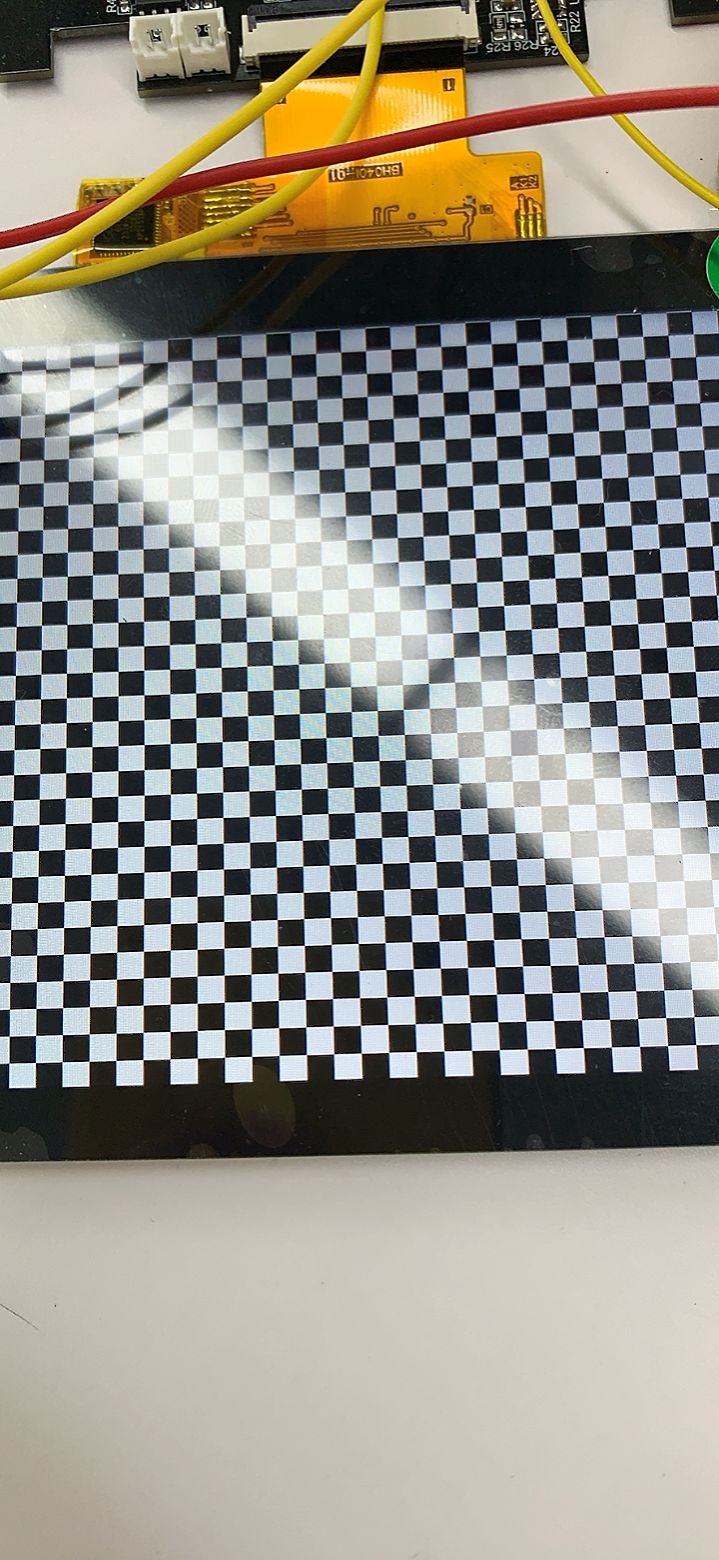
};现在如果我把panel这个"lg,lb070wv8", "simple-panel";节点注释掉的话,或者修改/drivers/gpu/drm/panel/panel-simple.c下lg,lb070wv8这个函数里的一些参数(比如把800x480修改成480x480),屏幕并不会显示我上面的黑白格demo。
所以我接下来的设备树该怎么使用,继续使用spi下面的st7701s节点还是在panel节点中添加st7701s驱动?
#33 Re: 全志 SOC » 求助 F1C100s使用 gpio模拟spi 驱动ST7701s spi9bit+rgb屏的问题 屏幕不亮 逻辑分析仪波形不对 » 2021-11-01 15:47:10
#35 Re: 全志 SOC » 求助 F1C100s使用 gpio模拟spi 驱动ST7701s spi9bit+rgb屏的问题 屏幕不亮 逻辑分析仪波形不对 » 2021-11-01 10:48:53
#38 全志 SOC » 求助 F1C100s使用 gpio模拟spi 驱动ST7701s spi9bit+rgb屏的问题 屏幕不亮 逻辑分析仪波形不对 » 2021-10-30 17:50:00
- HongSang
- 回复: 27
论坛的各位大哥们,小弟最近在f1c100s上调st7701s这个LCD驱动芯片,由于荔枝派的源码里没有/driver/staging/fbtfb/fb_st7701s.c驱动,所以仿照fb_st7789v.c修改了一个st7701s,只修改了 init_display()里面的初始化和一些匹配名字.spi总线使用的gpio模拟的.linux自带的spi-gpio.
个人的理解是 st7701s芯片挂载到gpio模拟的spi总线下面.然后使用spi总线通讯使芯片初始化并刷进去LCD参数,之后在使用fbfbt驱动生成fb设备.现在这个流程似乎都走通了...但是驱动的加载有些问题
问题描述:
现在设备开机能生成fb1设备,gpio模拟的spi的时钟和数据位也能收到波形(看data位的数据应该是不对的), 屏幕没有亮.
分析是st7701s驱动的问题.想请教下是不是仿照的/driver/staging/fbtfb/fb_st7701s.c驱动的原因.还有一个问题dmesg看到spi总线加载的log是使用的8bit.应该怎么样设备才能使用到9bit???是要在spi-gpio里设备还是st7701s驱动里会使用的9bit写入(比如 init_display()里的write_reg函数)
还有一点疑惑的是这两个驱动文件的区别是什么该用哪一个修改....
drivers/staging/fbtft/fb_st7789v.c
drivers/gpu/drm/panel/panel-sitronix-st7789v.c
请教下大佬们,我在源码里使用哪份驱动文件让st7701s芯片初始化.小弟卡在这好几天没有进展,现在脑子晕乎乎的....
请求指导 感动常在!
贴相关代码
设备树:
&spi1 {
	compatible = "spi-gpio";
	pinctrl-names = "default";
	pintrcl-0 = <&spi1_pins_a>;
	status = "okay";
	spi-max-frequency = <5000>; //这里用gpio模拟的spi总线所以我频率没有设置很高
	num-chipselects = <1>;

	gpio-sck = <&pio 0 1 0>;
	gpio-mosi = <&pio 4 9 0>;   //因为只需要写所以只用了一根数据线
	//gpio-miso = <&pio 4 10 0>; PE10
	cs-gpios = <&pio 0 0 0>; PA0
	//dc-gpios   直接供电不需要io配置供电

	bias-pull-up;

	st7701s@0 {
        status = "okay";
        compatible = "sitronix,st7701s";
        reg = <0>;
        spi-max-frequency =<5000>;
        rotate =<90>;
        spi-cpol;
        spi-cpha;
        rgb;
        fps =<30>;
        buswidth =<8>;
	reset-gpios=<&pio 4 5 GPIO_ACTIVE_HIGH>;
        debug =<1>;
};
PIO:
			spi1_pins_a: spi1-pins-pc {
				pins = "PA0", "PA1", "PE9", "PE10" , "PE5";
				function = "gpio_out";

			};
dmesg
# dmesg | grep spi
[    0.907933] spi_gpio_dt_init dts is ok //这句是自己加的
[    0.911901] spi dts is ok
[    0.915248] spi_gpio 1c06000.spi: registered master spi1
[    0.915657] spi spi1.0: spi_bitbang_setup, 200000 nsec/bit
[    0.915796] spi spi1.0: setup mode 3, 8 bits/w, 5000 Hz max --> 0 这里看出来没有使用到9bit
[    0.916295] spi_gpio 1c06000.spi: registered child spi1.0
[    0.917875] sun6i-spi 1c05000.spi: registered master spi0
[    0.918355] spi spi0.0: setup mode 0, 8 bits/w, 50000000 Hz max --> 0
[    0.919450] m25p80 spi0.0: found w25q128, expected xt25f128b  //////soiflash
[    0.925160] m25p80 spi0.0: w25q128 (16384 Kbytes)
[    0.930010] 4 ofpart partitions found on MTD device spi0.0
[    0.935494] Creating 4 MTD partitions on "spi0.0":                       /////spiflash
[    0.971392] sun6i-spi 1c05000.spi: registered child spi0.0
[    1.115866] fb_st7701s spi1.0: fbtft_request_one_gpio: 'reset-gpios' = GPIO133
[    1.123327] fb_st7701s spi1.0: fbtft_request_one_gpio: 'dc-gpios' = GPIO130
[    7.593663] graphics fb0: fb_st7701s frame buffer, 480x480, 450 KiB video memory, 4 KiB buffer memory, fps=33, spi1.0 at 0 MHz
drivers/staging/fbtft/fb_st7701s.c
#include <linux/bitops.h>
#include <linux/delay.h>
#include <linux/init.h>
#include <linux/kernel.h>
#include <linux/module.h>
#include <video/mipi_display.h>

#include "fbtft.h"

#define DRVNAME "fb_st7701s"

#define DEFAULT_GAMMA \
	"70 2C 2E 15 10 09 48 33 53 0B 19 18 20 25\n" \
	"70 2C 2E 15 10 09 48 33 53 0B 19 18 20 25"

enum st7701s_command {
	PORCTRL = 0xB2,
	GCTRL = 0xB7,
	VCOMS = 0xBB,
	VDVVRHEN = 0xC2,
	VRHS = 0xC3,
	VDVS = 0xC4,
	VCMOFSET = 0xC5,
	PWCTRL1 = 0xD0,
	PVGAMCTRL = 0xE0,
	NVGAMCTRL = 0xE1,
};

#define MADCTL_BGR BIT(3) /* bitmask for RGB/BGR order */
#define MADCTL_MV BIT(5) /* bitmask for page/column order */
#define MADCTL_MX BIT(6) /* bitmask for column address order */
#define MADCTL_MY BIT(7) /* bitmask for page address order */

static int init_display(struct fbtft_par *par)
{
	#if 0
	/* turn off sleep mode */
	write_reg(par, MIPI_DCS_EXIT_SLEEP_MODE);
	mdelay(120);

	/* set pixel format to RGB-565 */
	write_reg(par, MIPI_DCS_SET_PIXEL_FORMAT, MIPI_DCS_PIXEL_FMT_16BIT);

	write_reg(par, PORCTRL, 0x08, 0x08, 0x00, 0x22, 0x22);

	/*
	 * VGH = 13.26V
	 * VGL = -10.43V
	 */
	write_reg(par, GCTRL, 0x35);

	/*
	 * VDV and VRH register values come from command write
	 * (instead of NVM)
	 */
	write_reg(par, VDVVRHEN, 0x01, 0xFF);

	/*
	 * VAP =  4.1V + (VCOM + VCOM offset + 0.5 * VDV)
	 * VAN = -4.1V + (VCOM + VCOM offset + 0.5 * VDV)
	 */
	write_reg(par, VRHS, 0x0B);

	/* VDV = 0V */
	write_reg(par, VDVS, 0x20);

	/* VCOM = 0.9V */
	write_reg(par, VCOMS, 0x20);

	/* VCOM offset = 0V */
	write_reg(par, VCMOFSET, 0x20);

	/*
	 * AVDD = 6.8V
	 * AVCL = -4.8V
	 * VDS = 2.3V
	 */
	write_reg(par, PWCTRL1, 0xA4, 0xA1);

	write_reg(par, MIPI_DCS_SET_DISPLAY_ON);
	#endif
	par->fbtftops.reset(par);
	write_reg(par, 0xFF, 0x77, 0x01, 0x00, 0x00, 0x13);
	write_reg(par, 0xEF, 0x08);
	write_reg(par, 0xFF, 0x77, 0x01, 0x00, 0x00, 0x10);
	write_reg(par, 0xC0, 0x3B, 0x00);
	write_reg(par, 0xC1, 0x0D, 0x02);
	write_reg(par, 0xC2, 0x21, 0x08);
	.................
	return 0;
}

/**
 * set_var() - apply LCD properties like rotation and BGR mode
 *
 * @par: FBTFT parameter object
 *
 * Return: 0 on success, < 0 if error occurred.
 */
static int set_var(struct fbtft_par *par)
{
	u8 madctl_par = 0;

	if (par->bgr)
		madctl_par |= MADCTL_BGR;
	switch (par->info->var.rotate) {
	case 0:
		break;
	case 90:
		madctl_par |= (MADCTL_MV | MADCTL_MY);
		break;
	case 180:
		madctl_par |= (MADCTL_MX | MADCTL_MY);
		break;
	case 270:
		madctl_par |= (MADCTL_MV | MADCTL_MX);
		break;
	default:
		return -EINVAL;
	}
	write_reg(par, MIPI_DCS_SET_ADDRESS_MODE, madctl_par);
	return 0;
}

/**
 * set_gamma() - set gamma curves
 *
 * @par: FBTFT parameter object
 * @curves: gamma curves
 *
 * Before the gamma curves are applied, they are preprocessed with a bitmask
 * to ensure syntactically correct input for the display controller.
 * This implies that the curves input parameter might be changed by this
 * function and that illegal gamma values are auto-corrected and not
 * reported as errors.
 *
 * Return: 0 on success, < 0 if error occurred.
 */
static int set_gamma(struct fbtft_par *par, u32 *curves)
{
	int i;
	int j;
	int c; /* curve index offset */

	/*
	 * Bitmasks for gamma curve command parameters.
	 * The masks are the same for both positive and negative voltage
	 * gamma curves.
	 */
	static const u8 gamma_par_mask[] = {
		0xFF, /* V63[3:0], V0[3:0]*/
		0x3F, /* V1[5:0] */
		0x3F, /* V2[5:0] */
		0x1F, /* V4[4:0] */
		0x1F, /* V6[4:0] */
		0x3F, /* J0[1:0], V13[3:0] */
		0x7F, /* V20[6:0] */
		0x77, /* V36[2:0], V27[2:0] */
		0x7F, /* V43[6:0] */
		0x3F, /* J1[1:0], V50[3:0] */
		0x1F, /* V57[4:0] */
		0x1F, /* V59[4:0] */
		0x3F, /* V61[5:0] */
		0x3F, /* V62[5:0] */
	};

	for (i = 0; i < par->gamma.num_curves; i++) {
		c = i * par->gamma.num_values;
		for (j = 0; j < par->gamma.num_values; j++)
			curves[c + j] &= gamma_par_mask[j];
		write_reg(
			par, PVGAMCTRL + i,
			curves[c + 0], curves[c + 1], curves[c + 2],
			curves[c + 3], curves[c + 4], curves[c + 5],
			curves[c + 6], curves[c + 7], curves[c + 8],
			curves[c + 9], curves[c + 10], curves[c + 11],
			curves[c + 12], curves[c + 13]);
	}
	return 0;
}

/**
 * blank() - blank the display
 *
 * @par: FBTFT parameter object
 * @on: whether to enable or disable blanking the display
 *
 * Return: 0 on success, < 0 if error occurred.
 */
static int blank(struct fbtft_par *par, bool on)
{
	if (on)
		write_reg(par, MIPI_DCS_SET_DISPLAY_OFF);
	else
		write_reg(par, MIPI_DCS_SET_DISPLAY_ON);
	return 0;
}

static void write_register(struct fbtft_par *par, int len, ...)
{
	va_list args;
	int i;

	va_start(args, len);

	for (i = 0; i < len; i++)
		par->buf[i] = va_arg(args, unsigned int);

	/* keep DC low for all command bytes to transfer */
	fbtft_write_spi_emulate_9(par, par->buf, len, 0);

	va_end(args);
}

static struct fbtft_display display = {
	.regwidth = 8,
	.width = 480,
	.height = 480,
	.gamma_num = 2,
	.gamma_len = 14,
	.gamma = DEFAULT_GAMMA,
	.fbtftops = {
		.init_display = init_display,
		.set_var = set_var,
		.set_gamma = set_gamma,
		.blank = blank,
		.write_reg = write_register,
	},
};

FBTFT_REGISTER_DRIVER(DRVNAME, "sitronix,st7701s", &display);

MODULE_ALIAS("spi:" DRVNAME);
MODULE_ALIAS("platform:" DRVNAME);
MODULE_ALIAS("spi:st7701s");
MODULE_ALIAS("platform:st7701s");#39 Re: 全志 SOC » 请教ST7789V,不显示,发现波形完全不对!请高手指点一二!! » 2021-10-30 14:46:23
晕哥请问下这两个驱动程序有什么区别 都是生成fb设备的吗
#40 Re: 全志 SOC » F1C100 使用GPIO模拟SPI 驱动 st7789手表屏 » 2021-10-29 19:43:55
页次: 1
- 首页
- » 搜索
- » HongSang 发表的帖子
东莞哇酷科技有限公司开发