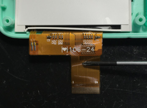
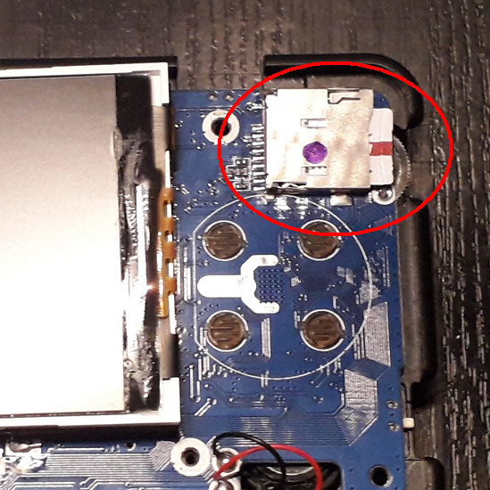
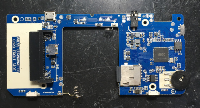
楼主 #804 2022-04-07 13:19:18 分享评论
#805 2022-04-07 13:55:28 分享评论
- kendling
- 会员
- 注册时间: 2022-03-04
- 已发帖子: 94
- 积分: 105
Re: 研究FC3000掌機的開源可行性
@kendling
我新買的IPS FC3000是V2版本,然後測試下你的fc3000_ips_od_jutleys_no_roms.img.7z,發現進入OD後,背光跟聲音都有,但是,屏沒有顯示~@zjzixuan
感謝你的好意,目前不需要~
@司徒 那就是屏幕初始化资料不同了,你那个 IPS 屏有点像旧的 TN 屏。你确定可视角度是 IPS ? 我看了你的 IPS 版拆机页面没有拍可视角度。
@zjzixuan 感謝你的好意,就目前的情况来看:就算新买一部 IPS ,屏幕也未必和你手上的一致。如果屏幕不一样,重新抓屏幕初始化资料还是不能适配你手上的那部 FC3000 。
离线
#806 2022-04-07 14:01:38 分享评论
- kendling
- 会员
- 注册时间: 2022-03-04
- 已发帖子: 94
- 积分: 105
Re: 研究FC3000掌機的開源可行性

@zjzixuan 你可以拆开看看,屏幕是否和我的一样,有个 35to24 的板子。如果一样可以试试下面这个包是否能驱动屏:
https://github.com/kendling/my_bin_file/releases/download/v1.0/fc3000_ips_od_jutleys_no_roms.img.7z
离线
#807 2022-04-07 14:30:54 分享评论
- kendling
- 会员
- 注册时间: 2022-03-04
- 已发帖子: 94
- 积分: 105
Re: 研究FC3000掌機的開源可行性
@司徒 指导一下那个电流声要怎么分析原因?我尝试解决。
离线
#808 2022-04-08 07:28:02 分享评论
- zjzixuan
- 会员
- 注册时间: 2022-04-04
- 已发帖子: 14
- 积分: 15
Re: 研究FC3000掌機的開源可行性
@kendling 我的屏和你的一模一样 用了你提供的固件可以正常使用 不完美的地方是屏的亮度不调到最大声音就有电流声
离线
#809 2022-04-08 07:34:25 分享评论
- kendling
- 会员
- 注册时间: 2022-03-04
- 已发帖子: 94
- 积分: 105
Re: 研究FC3000掌機的開源可行性
@zjzixuan
更正一下,usb 插座下面的小芯片应该是丝印 SL ,5V1A 的二极管。
参考这个链接:https://item.taobao.com/item.htm?id=671743757933

离线
#810 2022-04-09 08:20:53 分享评论
- kendling
- 会员
- 注册时间: 2022-03-04
- 已发帖子: 94
- 积分: 105
Re: 研究FC3000掌機的開源可行性
@kendling 我的屏和你的一模一样 用了你提供的固件可以正常使用 不完美的地方是屏的亮度不调到最大声音就有电流声
那我换一下 v1_v2_flash 的内核试试。
离线
#811 2022-04-09 09:26:42 分享评论
- zjzixuan
- 会员
- 注册时间: 2022-04-04
- 已发帖子: 14
- 积分: 15
Re: 研究FC3000掌機的開源可行性
@kendling 我用万能表测试了一下那个sl二极管 正反测试结果是178和870 应该是好的 我先买那个电源管理芯片关上看看
我的屏是RB411-11A
Q021E
最近编辑记录 zjzixuan (2022-04-09 09:30:15)
离线
#812 2022-04-09 22:59:49 分享评论
- kendling
- 会员
- 注册时间: 2022-03-04
- 已发帖子: 94
- 积分: 105
Re: 研究FC3000掌機的開源可行性
@kendling 我用万能表测试了一下那个sl二极管 正反测试结果是178和870 应该是好的 我先买那个电源管理芯片关上看看
我的屏是RB411-11A
Q021E
@zjzixuan
你用 fc3000_ips_od_jutleys_no_roms.img.7z 可以正常显示就说明屏幕和我的使用相同的初始化资料。
刚看了一下 v1_v2_flash.img,司徒把所有文档都写到预留给 uboot 的未分区空间里了。
我没有这些文档,暂时无法更新这个包。
离线
#813 2022-04-10 03:30:06 分享评论
- sionwave
- 会员
- 注册时间: 2022-04-10
- 已发帖子: 1
- 积分: 1
Re: 研究FC3000掌機的開源可行性
这个机器最大的槽点就是屏幕实在太烂了!
离线
#814 2022-04-10 09:32:41 分享评论
- kendling
- 会员
- 注册时间: 2022-03-04
- 已发帖子: 94
- 积分: 105
Re: 研究FC3000掌機的開源可行性
这个机器最大的槽点就是屏幕实在太烂了!
我觉得 ips 屏还好吧,拆开看显示效果很好。整机看交易差估计是封装的问题,改全贴合肯定可以提升显示效果。
另外还可以换高分辨率的屏。
离线
#815 2022-04-10 11:01:50 分享评论
- fullniz
- 会员
- 注册时间: 2021-09-17
- 已发帖子: 14
- 积分: 12.5
Re: 研究FC3000掌機的開源可行性
劳驾问下小横米的喇叭规格淘宝如何搜啊
不知道什么情况不响了,这也太脆弱了,也可能是我运气好
要是买不到大小一样的 我就买个小的,就是不知道怎么搜索这个喇叭
离线
楼主 #816 2022-04-10 16:48:50 分享评论
Re: 研究FC3000掌機的開源可行性
@fullniz
喇叭應該是找個形狀類似的就可以,小横米的喇叭规格不知道~
@kendling
我新買的FC3000 IPS屏(韌體是V2版本)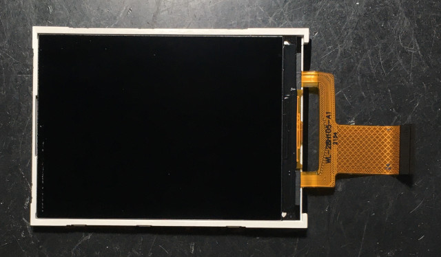
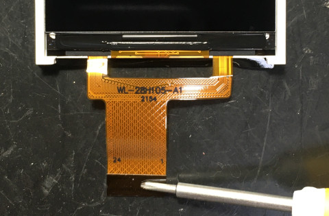
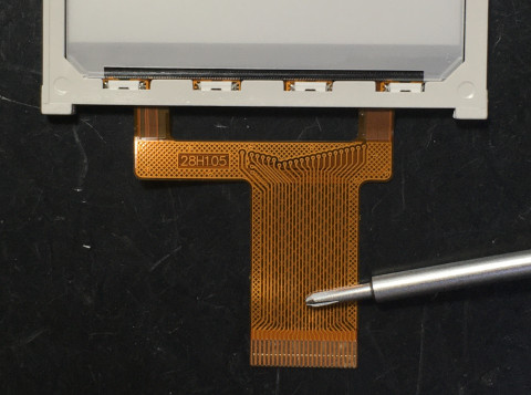
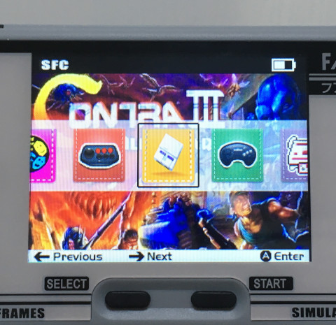
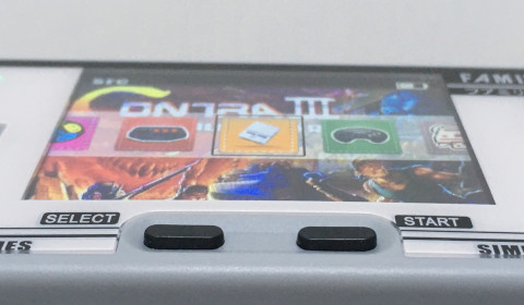
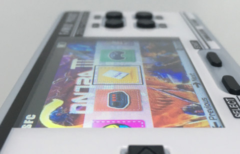
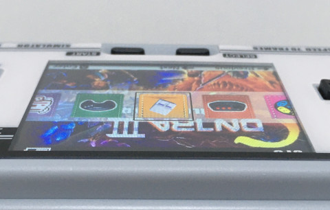
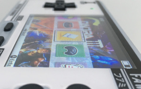
嘗試解析電流聲問題
依據網友測試,發現電流聲音跟LCD背光設定有關係,只要將LCD背光亮度調到100%,就不會有電流聲音,於是,司徒看一下PCB線路,發現聲音輸出是走在LCD背光電路旁邊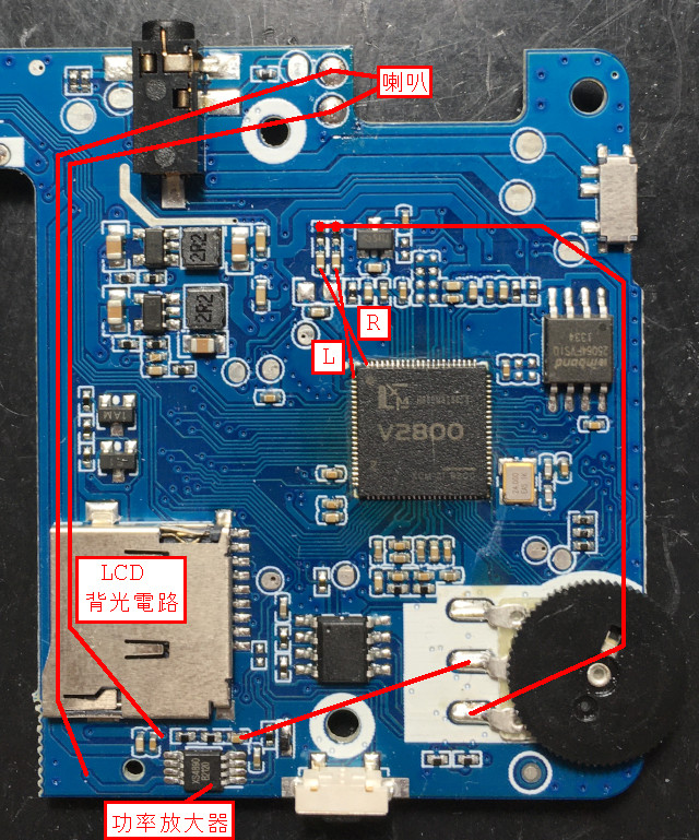
LCD背光使用PWM方式控制,亮度在100%時,輸出固定維持在高電位狀態,因此,不會有干擾的狀況發生,這也是為何原廠系統是固定在此亮度的原因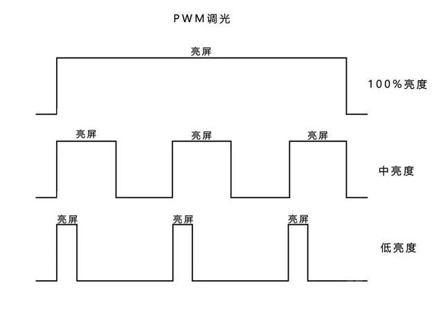
XS4890(LM4890)腳位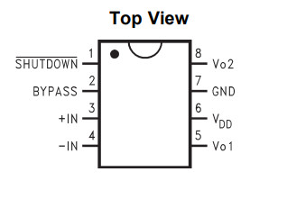
司徒看了一下PCB,發現FC3000使用的電路如下: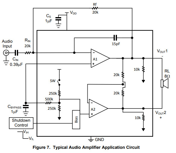
雖然目前看來,應該是輸出遭到EM干擾所造成的問題,不過,如果是輸入源遭到干擾,可以考慮改造成差分放大電路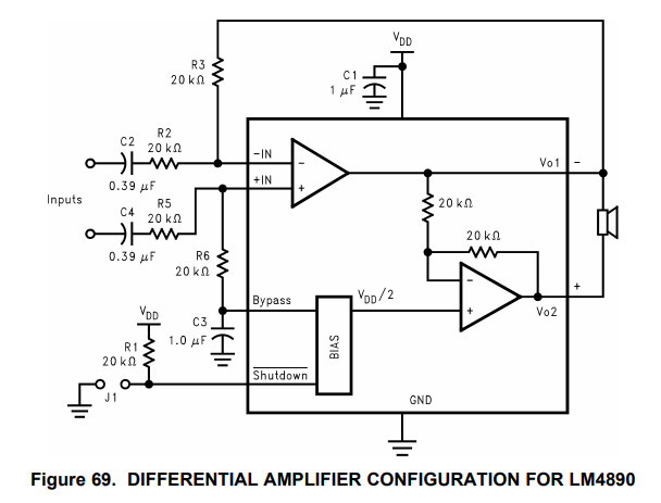
解法,大約有幾個思路:
軟體思考:
1. 可以依據LCD背光的頻率,疊加對應的波形,類似主動式噪音消除法,可以在聲音驅動實作
硬體思考:
1. 將啦叭輸出線路切斷(PCB),使用外圍有接地包覆的線材取代
2. 使用鐵片包覆LCD背光電路並且將鐵片接地
3. 將喇叭移到下方
离线
#817 2022-04-10 18:55:46 分享评论
#818 2022-04-10 22:02:29 分享评论
- kendling
- 会员
- 注册时间: 2022-03-04
- 已发帖子: 94
- 积分: 105
Re: 研究FC3000掌機的開源可行性
@司徒 ![]() 分析得好深入,可以当教学案例了。
分析得好深入,可以当教学案例了。
离线
楼主 #819 2022-04-11 13:04:38 分享评论
#820 2022-04-11 15:16:05 分享评论
- kendling
- 会员
- 注册时间: 2022-03-04
- 已发帖子: 94
- 积分: 105
Re: 研究FC3000掌機的開源可行性
@aozima
頻率跟亮度呈現正比,所以越高頻率,代表越亮,如果要固定亮度,則代表PWM失去作用~@kendling
我們需要勇者幫忙做實驗~
@司徒
我看看啥时候有空做做实验吧。
离线
楼主 #821 2022-04-11 18:18:38 分享评论
#822 2022-04-11 19:39:09 分享评论
- kendling
- 会员
- 注册时间: 2022-03-04
- 已发帖子: 94
- 积分: 105
Re: 研究FC3000掌機的開源可行性
@kendling
OK,不用有壓力~
@司徒![]() 学习状态,没压力。我本来是想尝试移植最新版 uboot 的(用现有的 uboot 代码参照修改,目前还没编译通过),现在先来做实验吧。
学习状态,没压力。我本来是想尝试移植最新版 uboot 的(用现有的 uboot 代码参照修改,目前还没编译通过),现在先来做实验吧。
离线
#823 2022-04-12 18:41:11 分享评论
- fjswxl
- 会员
- 注册时间: 2021-09-14
- 已发帖子: 3
- 积分: 2.5
Re: 研究FC3000掌機的開源可行性
小miyoo 的 ps1模拟器能更新下吗 玩不了nbalive99会卡界面, 看大米的ps模拟器就能玩
离线
楼主 #824 2022-04-13 13:16:30 分享评论
#825 2022-04-13 18:39:34 分享评论
- kendling
- 会员
- 注册时间: 2022-03-04
- 已发帖子: 94
- 积分: 105
Re: 研究FC3000掌機的開源可行性
@司徒
FC3000 十字键垫高的 STL 文件可以提供一下吗?
离线
楼主 #826 2022-04-13 20:09:33 分享评论
Re: 研究FC3000掌機的開源可行性
离线
#827 2022-04-13 22:06:38 分享评论
- kendling
- 会员
- 注册时间: 2022-03-04
- 已发帖子: 94
- 积分: 105
Re: 研究FC3000掌機的開源可行性
谢谢,我看看去某创打样要多少钱。
离线
#828 2022-04-14 10:56:11 分享评论
- kendling
- 会员
- 注册时间: 2022-03-04
- 已发帖子: 94
- 积分: 105
Re: 研究FC3000掌機的開源可行性
谢谢,我看看去某创打样要多少钱。
![]() 某创打样 2元/件,邮费至少要 6 元。。还是算了。
某创打样 2元/件,邮费至少要 6 元。。还是算了。
离线
楼主 #829 2022-04-14 13:14:13 分享评论
#830 2022-04-14 14:02:32 分享评论
- kendling
- 会员
- 注册时间: 2022-03-04
- 已发帖子: 94
- 积分: 105
Re: 研究FC3000掌機的開源可行性
可以考慮買一台便宜的FDM 3D Printer,這樣比較有樂趣,會開啟你很多奇特製作的想法~
感谢推荐,这个后面再说吧。FC3000 电流声的问题我要周六才有时间做实验。
离线
#831 2022-04-14 22:46:57 分享评论
- kendling
- 会员
- 注册时间: 2022-03-04
- 已发帖子: 94
- 积分: 105
Re: 研究FC3000掌機的開源可行性
@司徒
对了,那个外国友人成功点亮他的 ips 屏了没?
离线
#832 2022-04-15 23:31:29 分享评论
- fjswxl
- 会员
- 注册时间: 2021-09-14
- 已发帖子: 3
- 积分: 2.5
Re: 研究FC3000掌機的開源可行性
q90 刷这个横米修复系统 卡开机蓝屏
离线
#833 2022-04-17 20:20:05 分享评论
- kendling
- 会员
- 注册时间: 2022-03-04
- 已发帖子: 94
- 积分: 105
Re: 研究FC3000掌機的開源可行性
@司徒
第一个测试结果:
直接从功率放大器引线到喇叭,电流声还是存在,没有变化。
这个是不是代表和背光电路相关性不大了?
还是说,进入功率放大器之前就已经被干扰了?
离线
楼主 #834 2022-04-18 13:04:02 分享评论
#835 2022-04-18 14:42:25 分享评论
- kendling
- 会员
- 注册时间: 2022-03-04
- 已发帖子: 94
- 积分: 105
Re: 研究FC3000掌機的開源可行性
@kendling
後來老外應該是沒有點亮IPS屏,不然我應該是可以知道~哈~
直接从功率放大器引线到喇叭,但是,你PCB線有斷開嗎 ?原本拉出去的PCB線也要斷開,不然,還是會被干擾回去~
@司徒
PCB 倒是没有断开哦。:) 我原来是想做无损实验,所以只是用测试夹在功率放大器引线出来而已。那我再试试割断 PCB 之后还会不会有影响吧。
离线
#836 2022-04-19 01:06:37 分享评论
- leonierx
- 会员
- 注册时间: 2022-04-19
- 已发帖子: 1
- 积分: 1
Re: 研究FC3000掌機的開源可行性
报告个问题,我的ips版fc3000用fc3000_ips_od_jutleys_no_roms.img.7z可以启动可以玩,就是屏幕有时有残影,而且目视刷新率没有60hz,画面有撕裂,和tft lcd版比较非常明显。
离线
楼主 #837 2022-04-19 12:40:16 分享评论
#838 2022-04-20 13:43:51 分享评论
- kit0072
- 会员
- 注册时间: 2021-07-08
- 已发帖子: 10
- 积分: 8
Re: 研究FC3000掌機的開源可行性
我后悔没备份此贴子,很多图片都死图了 。
离线
#839 2022-04-21 11:00:40 分享评论
- kendling
- 会员
- 注册时间: 2022-03-04
- 已发帖子: 94
- 积分: 105
Re: 研究FC3000掌機的開源可行性
我后悔没备份此贴子,很多图片都死图了 。
司徒的个人网站有有他的研究记录。
离线
#840 2022-04-21 14:59:31 分享评论
- zjzixuan
- 会员
- 注册时间: 2022-04-04
- 已发帖子: 14
- 积分: 15
Re: 研究FC3000掌機的開源可行性
@kendling 哪个模拟器可以玩igs三国战纪3
离线
#841 2022-04-21 16:51:40 分享评论
#842 2022-04-21 17:19:57 分享评论
- kendling
- 会员
- 注册时间: 2022-03-04
- 已发帖子: 94
- 积分: 105
Re: 研究FC3000掌機的開源可行性
@kendling 哪个模拟器可以玩igs三国战纪3
@zjzixuan
你试试 MAME 。
离线
楼主 #843 2022-04-21 21:12:13 分享评论
#844 2022-04-21 22:42:31 分享评论
- kendling
- 会员
- 注册时间: 2022-03-04
- 已发帖子: 94
- 积分: 105
Re: 研究FC3000掌機的開源可行性
@司徒
测试二:
功率放大器输出割断之后直接引线到喇叭没有声音了,是否线路后面还有元件?
我测过两条引线有大概有 20 千欧电阻,应该没有引错(我用测试夹引线)。
我看再找时间焊接引线试试吧。
离线
楼主 #845 2022-04-22 20:30:25 分享评论
#846 2022-04-23 01:51:23 分享评论
- sswater
- 会员
- 注册时间: 2022-02-11
- 已发帖子: 2
- 积分: 42
Re: 研究FC3000掌機的開源可行性
信息量太大,收藏备用!
离线
#847 2022-04-24 10:28:01 分享评论
- kendling
- 会员
- 注册时间: 2022-03-04
- 已发帖子: 94
- 积分: 105
Re: 研究FC3000掌機的開源可行性
@kendling
應該不會,官方也是建議這樣接的,你拍下你的PCB~
@司徒
昨天末没空,我晚上拍一下。我
测量了一下,接喇叭的是功率放大器向着电池方向最外面 2 个引脚。
我就是所这两个引脚外面的引线割断了,直接在引脚处接喇叭。
离线
#848 2022-04-24 23:34:07 分享评论
- kendling
- 会员
- 注册时间: 2022-03-04
- 已发帖子: 94
- 积分: 105
Re: 研究FC3000掌機的開源可行性
@司徒
我割的时候没有留意靠 tf 卡这边的引脚是连着电阻的。
离线
#849 2022-04-29 19:49:07 分享评论
- k3355792
- 会员
- 注册时间: 2022-04-29
- 已发帖子: 3
- 积分: 3
Re: 研究FC3000掌機的開源可行性
@司徒
问一下大大,我的横米miyoo的屏幕漏液可以用这个屏幕代替吗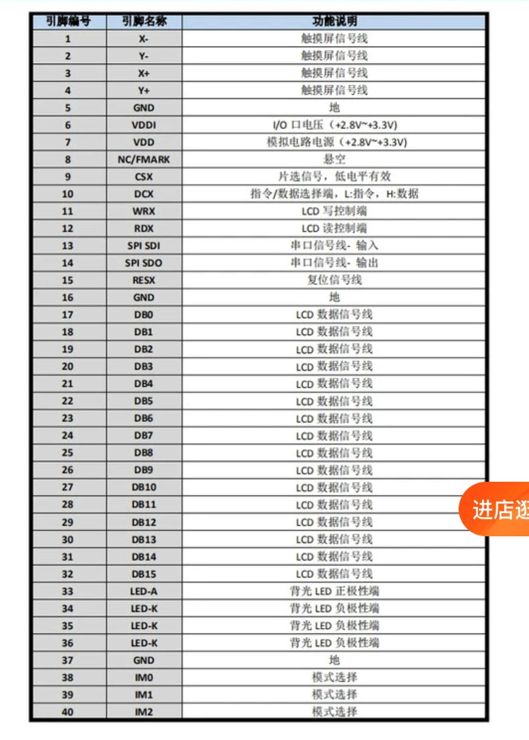
最近编辑记录 k3355792 (2022-04-29 19:49:36)
离线
#850 2022-04-30 08:33:15 分享评论
- huanxing
- 会员
- 注册时间: 2021-06-27
- 已发帖子: 33
- 积分: 34.5
Re: 研究FC3000掌機的開源可行性
还要看屏IC是否7789,有否TE同步脚位,没有的只能用回之前原机的旧系统且画面会撕裂,还要制作排线接口转接的PCB小板子,绝不是直插上能用的。司徒后期的新系统需TE配合。但尺寸、IC、信号类型符合并有TE的屏不易找的,基本是要定制
最近编辑记录 huanxing (2022-04-30 08:44:31)
离线
#851 2022-04-30 15:50:17 分享评论
- kendling
- 会员
- 注册时间: 2022-03-04
- 已发帖子: 94
- 积分: 105
Re: 研究FC3000掌機的開源可行性
@司徒
测试三:
还是有电流声!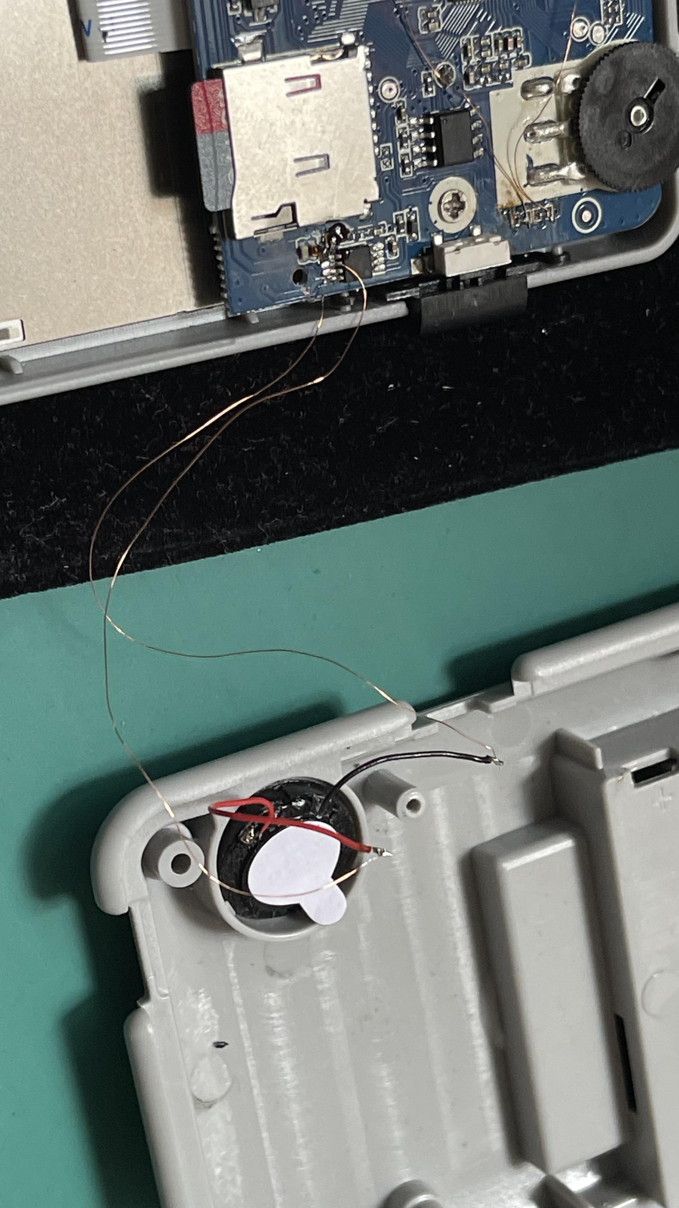
离线
楼主 #852 2022-05-03 13:17:29 分享评论
Re: 研究FC3000掌機的開源可行性
@kendling
感謝你的測試,PCB部分是從功放IC連接到耳機孔,所以耳機孔那端也要斷開,因為餘線還是靠在LCD背光旁邊,會從餘線導回耳機孔,耳機孔是連接到F1C100S的LR音頻腳位~
@k3355792
你這個屏的腳位不對,你可以看下這個原理圖:
https://github.com/steward-fu/pocketgo/releases/download/v1.0/schematic.pdf
离线
#853 2022-05-04 13:50:15 分享评论
- k3355792
- 会员
- 注册时间: 2022-04-29
- 已发帖子: 3
- 积分: 3
Re: 研究FC3000掌機的開源可行性
@司徒
感谢大大,理解了
离线
#854 2022-05-08 10:01:50 分享评论
- kendling
- 会员
- 注册时间: 2022-03-04
- 已发帖子: 94
- 积分: 105
Re: 研究FC3000掌機的開源可行性
@司徒
测试四:
电流声依旧!
下面是我割 PCB 的位置,不知道是不是位置有错?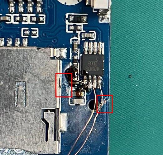
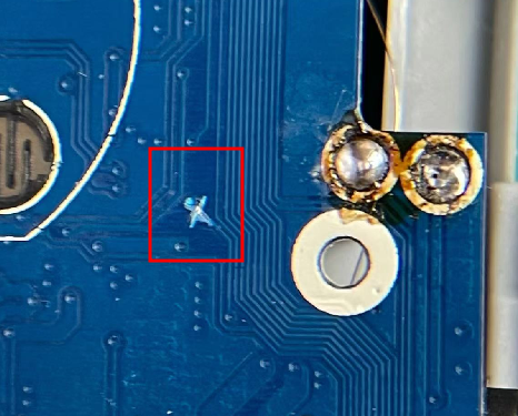
离线
楼主 #855 2022-05-12 22:48:17 分享评论
Re: 研究FC3000掌機的開源可行性
@kendling
相當感謝你的實驗,我原本的用意只是想把你機器搞壞,然後,你就自我放棄,想不到你是殺不死的蟑螂,感動上天,馬祖託夢叫司徒需要關心一下~
接著司徒開始嘗試解決噪音問題,首先,標注相關線路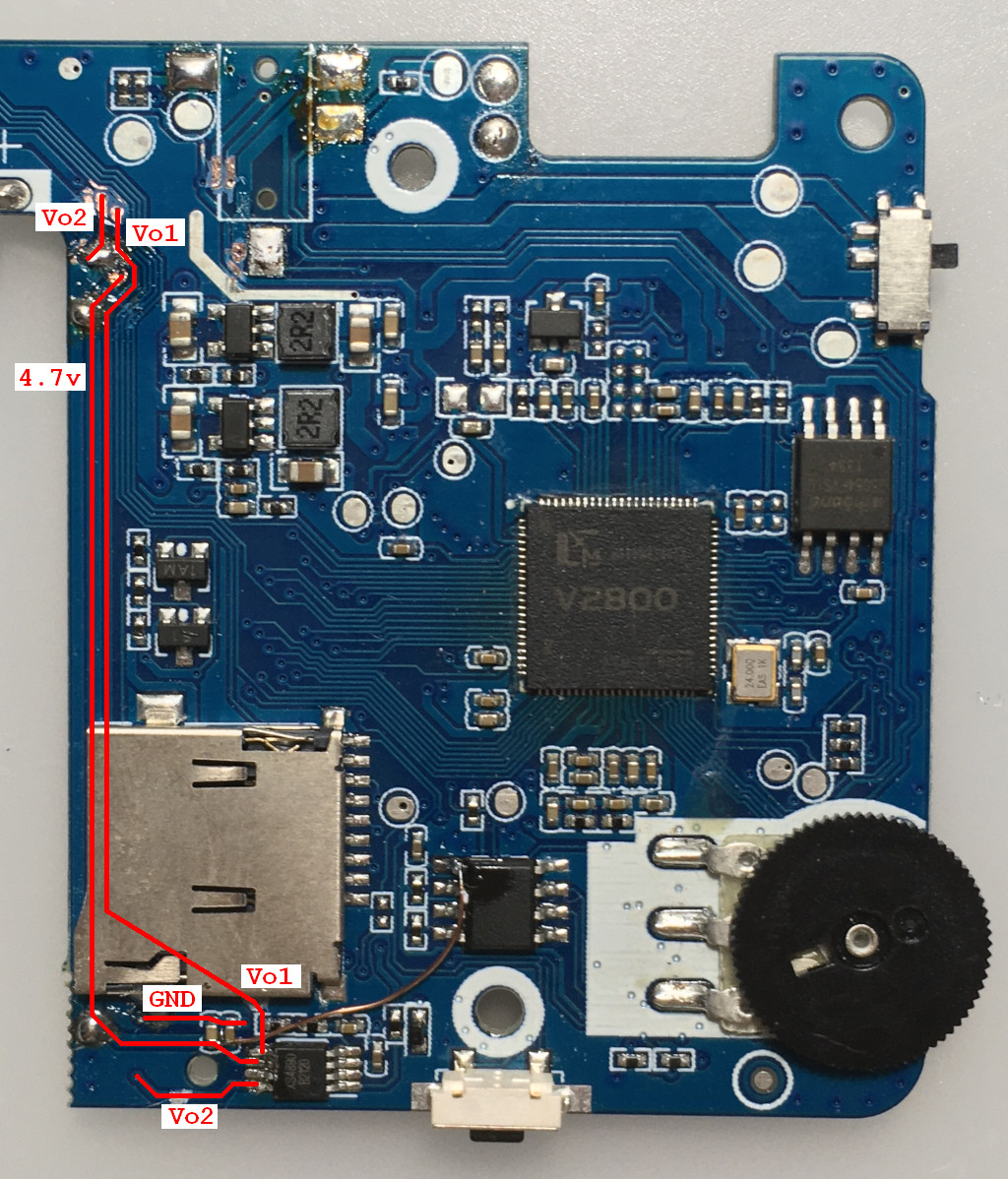
背面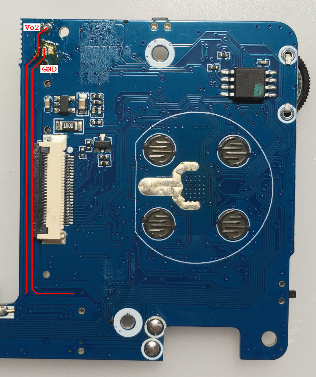
1:Vo2割斷,下半部份接地
2:Vo1割斷,下半部份接地
3:Vo2、Vo1、GND接在一起
4:4.7v割斷
5:4.7v下半部份接地
6:4.7v下半部份接地
7:GND接MicroSD的GND(這個可以省略)
8:Vo1割斷
9:Vo2割斷
LM4890第5腳接喇叭
LM4890第6腳連接到加密IC第一腳位3.3V
LM4890第8腳接喇叭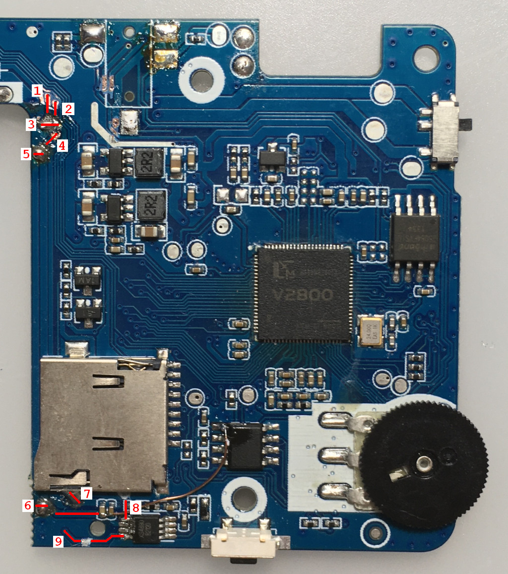
Vo2下半部份接地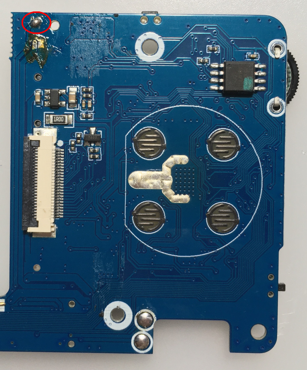
連接示波器量測訊號(需要掛上喇叭負載)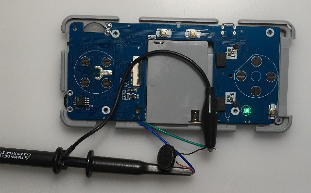
官方系統開機後,量測的喇叭訊號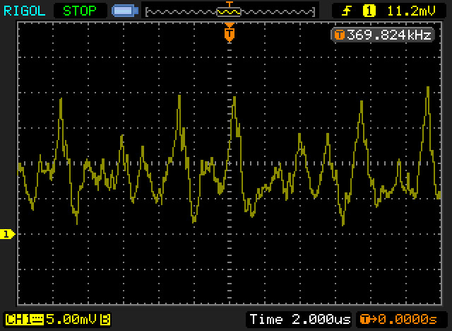
OD系統開機後,量測的喇叭訊號(4.7v割斷,但是沒有接地)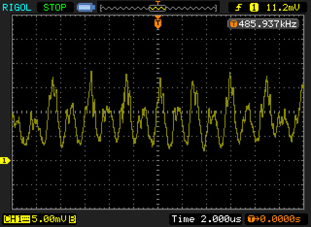
OD系統開機後,量測的喇叭訊號(4.7v割斷,餘線部份接地)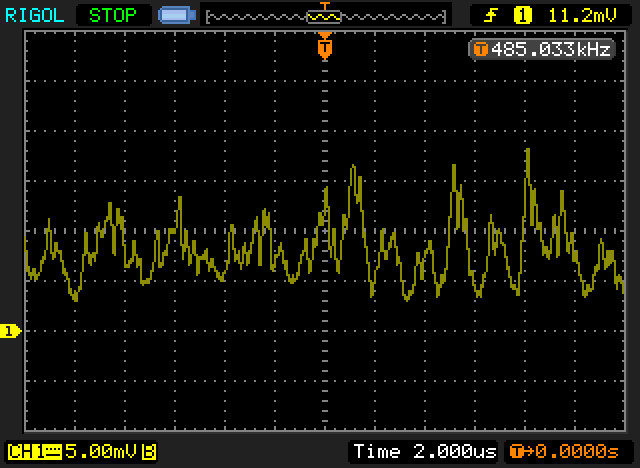
從量測到的訊號,可以發現4.7v那根線是一個關鍵性的影響,因為有一個很穩定影響波形,這個波形應該就是LCD背光震盪電路,因此,玩家也可以先從4.7v割斷開始改造,目前司徒測試改造後的電流聲音,已經跟原廠系統幾乎一樣
离线
#856 2022-05-12 23:16:12 分享评论
- fullniz
- 会员
- 注册时间: 2021-09-17
- 已发帖子: 14
- 积分: 12.5
Re: 研究FC3000掌機的開源可行性
横米玩着玩着会时不时出"噗"的一声音量很大的杂音:不知道是喇叭不好还是像这个一样或其他干扰?
我拆开看到主芯片f1c100s上方还有一个8管脚芯片空白未焊,
不知道是否为了节省成本少焊了些应有原件和使用了些低端原件,
要是有办法提高音质减少杂音尤其是那很突兀的"噗"就好了
离线
楼主 #857 2022-05-13 12:24:00 分享评论
#858 2022-05-13 13:03:58 分享评论
- kendling
- 会员
- 注册时间: 2022-03-04
- 已发帖子: 94
- 积分: 105
Re: 研究FC3000掌機的開源可行性
@司徒
感谢回答!果然还是我没做够。
电路基础薄弱啊,是该补补了。
离线
#859 2022-05-13 14:54:12 分享评论
- liozeng
- 会员
- 注册时间: 2022-04-11
- 已发帖子: 25
- 积分: 0
Re: 研究FC3000掌機的開源可行性
@aozima
頻率跟亮度呈現正比,所以越高頻率,代表越亮,如果要固定亮度,則代表PWM失去作用~@kendling
我們需要勇者幫忙做實驗~
大神,一般情况下: 屏幕亮度应该跟PWM的占空比成正比吧
离线
楼主 #860 2022-05-13 15:47:21 分享评论
#861 2022-05-16 10:32:45 分享评论
- kendling
- 会员
- 注册时间: 2022-03-04
- 已发帖子: 94
- 积分: 105
Re: 研究FC3000掌機的開源可行性
@司徒
对了,司徒,你找到的这个 4.7v 是不是屏幕的供电电压?直接接地会不会影响屏幕的供电?
离线
楼主 #862 2022-05-16 12:53:00 分享评论
Re: 研究FC3000掌機的開源可行性
屏幕供電(LED或核心電壓)一般來說不會使用不穩定的電壓(如:電池會隨著使用時間下降電壓),一般都是使用背光IC或者電源切換IC,省電路元件的可能會使用MOSFET(適用於並聯LED),而且根據之前量測的結果,FC3000的屏不是使用電池的4.7v,而根據LM4890手冊描述,LM4890可以工作的電壓是2.2~5.5v,LM4890手冊有做一些詳細測試數據,對於FC3000來說,把LM4890電壓接到3.3v,是可行的,所以目前看來,這個雜訊,很大一部分是從背光電路經由4.7v電源線灌入LM4890供放IC,所以我把電源線割斷,中間部分接地做屏蔽用途~
离线
#863 2022-05-17 13:56:54 分享评论
- kendling
- 会员
- 注册时间: 2022-03-04
- 已发帖子: 94
- 积分: 105
Re: 研究FC3000掌機的開源可行性
@司徒
感谢回答。学习了。
另外:如果不把 LM4890 的电压接到 3.3v,在其 4.7v 引入 LM4890 之前增加电容进行滤波,理论上是否可解决此问题?
离线
#864 2022-05-17 23:12:33 分享评论
- xiaoyu356
- 会员
- 注册时间: 2022-05-17
- 已发帖子: 7
- 积分: 7
Re: 研究FC3000掌機的開源可行性
真是强到全宇宙了啊 。。。。各种飞线 对于我这种手残党来说 只能看看图片了 呵呵
离线
楼主 #865 2022-05-19 07:20:41 分享评论
#866 2022-05-20 10:04:20 分享评论
- kendling
- 会员
- 注册时间: 2022-03-04
- 已发帖子: 94
- 积分: 105
Re: 研究FC3000掌機的開源可行性
@kendling
對~這個可以測試下~
接多大的电容应该怎么计算?
离线
楼主 #867 2022-05-22 21:31:43 分享评论
#868 2022-05-24 15:59:50 分享评论
- kendling
- 会员
- 注册时间: 2022-03-04
- 已发帖子: 94
- 积分: 105
Re: 研究FC3000掌機的開源可行性
@kendling
一般旁路電容使用1uF、0.1uF、0.01uF,你可以在功放的電源接腳做測試~
好,我抽空测试一下。
离线
#869 2022-05-28 02:03:04 分享评论
- tiopex
- 会员
- 注册时间: 2022-05-28
- 已发帖子: 5
- 积分: 1
Re: 研究FC3000掌機的開源可行性
@geekchun this link with modified steward source for q8 LCD has expired https://pan.baidu.com/s/19snjAws6KQ8AXpDDyKzs_g
提取码:r2yy
Could you reupload these sources?
Thanks
离线
#870 2022-05-28 14:31:17 分享评论
- geekchun
- 会员
- 注册时间: 2020-11-11
- 已发帖子: 75
- 积分: 105
Re: 研究FC3000掌機的開源可行性
@tiopex
当然可以
链接:https://pan.baidu.com/s/1qOgtu5qJJO5_W9pS6_wRYA
提取码:grko
离线
#871 2022-05-28 22:42:59 分享评论
- tiopex
- 会员
- 注册时间: 2022-05-28
- 已发帖子: 5
- 积分: 1
Re: 研究FC3000掌機的開源可行性
@geekchun
Thank you very much.
Do you have also uboot sources used in this img, or diff (patch) with fix video?
I'm working on open source cfw for q8 and sup m3 console basing on miyoo cfw, everything's works fine (keymap, volume control) except video problem with q8.
Here is the kernel source on which I'm working: https://github.com/tiopex/kernel
Thanks.
最近编辑记录 tiopex (2022-05-28 22:50:53)
离线
楼主 #872 2022-05-28 23:29:37 分享评论
#873 2022-05-29 00:43:20 分享评论
- tiopex
- 会员
- 注册时间: 2022-05-28
- 已发帖子: 5
- 积分: 1
离线
楼主 #874 2022-05-29 11:41:17 分享评论
Re: 研究FC3000掌機的開源可行性
@tiopex
May I know LCD works or not on your Q8 handheld after uses the image file provided by geekchun ?
If not work, according to the image you provided, I guess the model should be GC9306 or ST7789.
In your GitHub repo, the initialization code of ST7789 was located in panel_init() in r61520fb.c file.
You can try it firstly.
离线
楼主 #875 2022-05-29 11:53:59 分享评论
Re: 研究FC3000掌機的開源可行性
The LCD model is same as https://whycan.com/t_6647_2.html#p65793
离线
#876 2022-05-29 13:28:36 分享评论
- tiopex
- 会员
- 注册时间: 2022-05-28
- 已发帖子: 5
- 积分: 1
Re: 研究FC3000掌機的開源可行性
@司徒
Yes, it's works with R61520 but some colors are saturated with grain. On img from @geekchun all colors are fine with no issues. Also when I use uboot from @geekchun img and my kernel, colors also are fine.
On uboot from https://github.com/steward-fu/q8 also same colors issues saturated with grain
离线
楼主 #877 2022-05-29 14:11:00 分享评论
#878 2022-05-29 14:20:47 分享评论
- lzgame02
- 会员
- 注册时间: 2021-07-08
- 已发帖子: 45
- 积分: 47.5
Re: 研究FC3000掌機的開源可行性
The LCD model is same as https://whycan.com/t_6647_2.html#p65793
Which one is better you think ? IDA Pro or Ollydbg ?
离线
#879 2022-05-29 15:47:34 分享评论
- geekchun
- 会员
- 注册时间: 2020-11-11
- 已发帖子: 75
- 积分: 105
Re: 研究FC3000掌機的開源可行性
@司徒
司徒先生好,代码在我笔记本上,没有带回家,明天上班我会发出来
离线
#880 2022-05-29 15:53:53 分享评论
- geekchun
- 会员
- 注册时间: 2020-11-11
- 已发帖子: 75
- 积分: 105
Re: 研究FC3000掌機的開源可行性
@司徒
如您所说,驱动IC正是GC9306,我参考的初始化序列如下,我记得只修改了旋转方向,您可以先参考下,修改后的我明天发出来
    //------------- display control setting -----------------------//
    LCD_WR_REG(0xfe);
    LCD_WR_REG(0xef);
    LCD_WR_REG(0x36);
    //  LCD_WR_DATA(0x48);      //   Y=0 X=1 V=0 L=0     0x48
    LCD_WR_DATA(0x98);      //  Y=1 X=0 V=0 L=1    0x98
    LCD_WR_REG(0x3a);
    LCD_WR_DATA(0x05);

    LCD_WR_REG(0x35);
    LCD_WR_DATA(0x00);
    LCD_WR_REG(0x44);
    LCD_WR_DATA(0x00);
    LCD_WR_DATA(0x60);

    //------end display control setting----//
    //------Power Control Registers Initial----//
    LCD_WR_REG(0xa4);
    LCD_WR_DATA(0x44);
    LCD_WR_DATA(0x44);
    LCD_WR_REG(0xa5);
    LCD_WR_DATA(0x42);
    LCD_WR_DATA(0x42);
    LCD_WR_REG(0xaa);
    LCD_WR_DATA(0x88);
    LCD_WR_DATA(0x88);
    LCD_WR_REG(0xe8);
    LCD_WR_DATA(0x11);
    LCD_WR_DATA(0x71);
    LCD_WR_REG(0xe3);
    LCD_WR_DATA(0x01);
    LCD_WR_DATA(0x10);
    LCD_WR_REG(0xff);
    LCD_WR_DATA(0x61);
    LCD_WR_REG(0xAC);
    LCD_WR_DATA(0x00);

    LCD_WR_REG(0xAe);
    LCD_WR_DATA(0x2b);

    LCD_WR_REG(0xAd);
    LCD_WR_DATA(0x33);
    LCD_WR_REG(0xAf);
    LCD_WR_DATA(0x55);
    LCD_WR_REG(0xa6);
    LCD_WR_DATA(0x2a);
    LCD_WR_DATA(0x2a);
    LCD_WR_REG(0xa7);
    LCD_WR_DATA(0x2b);
    LCD_WR_DATA(0x2b);
    LCD_WR_REG(0xa8);
    LCD_WR_DATA(0x18);
    LCD_WR_DATA(0x18);
    LCD_WR_REG(0xa9);
    LCD_WR_DATA(0x2a);
    LCD_WR_DATA(0x2a);
    //-----display window 240X320---------//
    LCD_WR_REG(0x2a);
    LCD_WR_DATA(0x00);
    LCD_WR_DATA(0x00);
    LCD_WR_DATA(0x00);
    LCD_WR_DATA(0xef);
    LCD_WR_REG(0x2b);       // 0x002B = 239
    LCD_WR_DATA(0x00);
    LCD_WR_DATA(0x00);
    LCD_WR_DATA(0x01);
    LCD_WR_DATA(0x3f);      // 0x013F = 319
    //    LCD_WR_REG(0x2c);
    //--------end display window --------------//
    //------------gamma setting------------------//
    LCD_WR_REG(0xf0);
    LCD_WR_DATA(0x02);
    LCD_WR_DATA(0x01);
    LCD_WR_DATA(0x00);
    LCD_WR_DATA(0x00);
    LCD_WR_DATA(0x02);
    LCD_WR_DATA(0x09);

    LCD_WR_REG(0xf1);
    LCD_WR_DATA(0x01);
    LCD_WR_DATA(0x02);
    LCD_WR_DATA(0x00);
    LCD_WR_DATA(0x11);
    LCD_WR_DATA(0x1c);
    LCD_WR_DATA(0x15);

    LCD_WR_REG(0xf2);
    LCD_WR_DATA(0x0a);
    LCD_WR_DATA(0x07);
    LCD_WR_DATA(0x29);
    LCD_WR_DATA(0x04);
    LCD_WR_DATA(0x04);
    LCD_WR_DATA(0x38);//v43n  39

    LCD_WR_REG(0xf3);
    LCD_WR_DATA(0x15);
    LCD_WR_DATA(0x0d);
    LCD_WR_DATA(0x55);
    LCD_WR_DATA(0x04);
    LCD_WR_DATA(0x03);
    LCD_WR_DATA(0x65);//v43p 66

    LCD_WR_REG(0xf4);
    LCD_WR_DATA(0x0f);//v50n
    LCD_WR_DATA(0x1d);//v57n
    LCD_WR_DATA(0x1e);//v59n
    LCD_WR_DATA(0x0a);//v61n 0b
    LCD_WR_DATA(0x0d);//v62n 0d
    LCD_WR_DATA(0x0f);

    LCD_WR_REG(0xf5);
    LCD_WR_DATA(0x05);//v50p
    LCD_WR_DATA(0x12);//v57p
    LCD_WR_DATA(0x11);//v59p
    LCD_WR_DATA(0x34);//v61p 35
    LCD_WR_DATA(0x34);//v62p 34
    LCD_WR_DATA(0x0f);
    //-------end gamma setting----//
    LCD_WR_REG(0x11);       // SleepOut
    HAL_Delay(120);
    LCD_WR_REG(0x29);       // Display ON
    LCD_WR_REG(0x2c);
最近编辑记录 geekchun (2022-05-29 15:55:18)
离线
#881 2022-05-29 18:12:31 分享评论
- lzgame02
- 会员
- 注册时间: 2021-07-08
- 已发帖子: 45
- 积分: 47.5
Re: 研究FC3000掌機的開源可行性
@geekchun
只改旋轉方向 , 該不會是我之前貼地去改的吧 .....
那個有的刷完的確是上下顛倒的 ....
离线
#882 2022-05-29 19:34:01 分享评论
- geekchun
- 会员
- 注册时间: 2020-11-11
- 已发帖子: 75
- 积分: 105
Re: 研究FC3000掌機的開源可行性
@lzgame02
不太明白你说的
离线
#883 2022-05-30 01:30:41 分享评论
- tiopex
- 会员
- 注册时间: 2022-05-28
- 已发帖子: 5
- 积分: 1
Re: 研究FC3000掌機的開源可行性
@geekchun @司徒
Thank you very much for your help, everything works fine.
离线
#884 2022-05-30 08:28:41 分享评论
楼主 #885 2022-05-30 10:25:15 分享评论
Re: 研究FC3000掌機的開源可行性
@lzgame02
小強~好久不見了~IDA Pro比適合用於靜態分析,OllyDbg比較適合用於Windows PE檔案做動態分析,兩個都是很經典好用,如果可以不要逆向,那是最好,因為太花時間了,對於時間上來說,不見得划算,當然,不得已,那只能逆向了~
@tiopex
Welcome~
I am happy you can find the solution in this website.
The latest revised kernel source has been uploaded by geekchun today.
You can download and test it to see whether it has more better than previous one or not.
Backup source code has been put on: https://github.com/steward-fu/q8/releases/download/v1.1/lcd_q8_tf28qs006a.7z
@geekchun
相當感謝你的幫助,也感謝你開源出來讓大家使用,感謝~
离线
#886 2022-05-30 10:45:27 分享评论
- geekchun
- 会员
- 注册时间: 2020-11-11
- 已发帖子: 75
- 积分: 105
Re: 研究FC3000掌機的開源可行性
一直在享用司徒先生做的系统,今天终于也能做出一点点细微的贡献,相当开心哈哈哈
离线
#887 2022-06-03 21:16:27 分享评论
- lzgame02
- 会员
- 注册时间: 2021-07-08
- 已发帖子: 45
- 积分: 47.5
Re: 研究FC3000掌機的開源可行性
@司徒
XYC Q8 的套娃機 SUP M3 基本上也成了 .....
這套娃好像淘寶上一堆 , 霸王小子 , 酷孩 RS-77 也是的樣子 ......
上面那老外的 github 上好像有開源的樣子 .....
既然驅動應該都有了 , 那 ..... 剩下的就 ..... 交給掌機買的多的處理了 .....
畢竟在下也只有一台 Q8 而已 ....

最近编辑记录 lzgame02 (2022-06-03 21:19:45)
离线
楼主 #888 2022-06-04 11:52:42 分享评论
#889 2022-06-05 08:35:52 分享评论
- geekchun
- 会员
- 注册时间: 2020-11-11
- 已发帖子: 75
- 积分: 105
Re: 研究FC3000掌機的開源可行性
@lzgame02
牛哇~想收集全系列套娃机器
离线
#890 2022-06-06 11:08:28 分享评论
- lzgame02
- 会员
- 注册时间: 2021-07-08
- 已发帖子: 45
- 积分: 47.5
Re: 研究FC3000掌機的開源可行性
@lzgame02
牛哇~想收集全系列套娃机器
酷孩的 Rs-77 看起來跟 m3/q8 屬同一類的套娃 , 群內有人刷成功了 ....
上面那老外 github 上的固件看起來也成 , 應該跟 q8 m3 螢幕驅動都差不多

最近编辑记录 lzgame02 (2022-06-06 11:12:46)
离线
#891 2022-06-06 11:38:16 分享评论
- geekchun
- 会员
- 注册时间: 2020-11-11
- 已发帖子: 75
- 积分: 105
Re: 研究FC3000掌機的開源可行性
@lzgame02
可惜屏幕素质真的感人,有时间找找同IC同尺寸的IPS屏替代
离线
#892 2022-06-06 12:56:33 分享评论
- lzgame02
- 会员
- 注册时间: 2021-07-08
- 已发帖子: 45
- 积分: 47.5
Re: 研究FC3000掌機的開源可行性
@lzgame02
可惜屏幕素质真的感人,有时间找找同IC同尺寸的IPS屏替代
這台以前我買過 , 後來丟了換 Q8 .....
螢幕作工都不怎樣 , 電池還是強力膠黏在基板後面的 ....
感覺還是買可換電池的 Q8 / M3 之類的
或是高檔些的會比較好 ....
离线
#894 2022-06-12 19:51:15 分享评论
- txusevas
- 会员
- 注册时间: 2022-06-12
- 已发帖子: 3
- 积分: 3
Re: 研究FC3000掌機的開源可行性
@司徒
你好,
我需要为这个 IPS 显示器“WL-28H105-A1”刷固件。有人可以把文件发给我恢复吗?
我的单位死了,只能在电视上播放。非常感谢
离线
楼主 #895 2022-06-13 10:21:36 分享评论
#896 2022-06-18 19:38:38 分享评论
- zjzixuan
- 会员
- 注册时间: 2022-04-04
- 已发帖子: 14
- 积分: 15
Re: 研究FC3000掌機的開源可行性
@司徒 大佬啥时候出掌机啊 只有大佬你在用心研究这开源掌机 我们大家都欠你一个掌机
离线
楼主 #897 2022-06-18 21:15:19 分享评论
楼主 #898 2022-06-25 20:12:24 分享评论
Re: 研究FC3000掌機的開源可行性
@txusevas
Thank you for providing stock rom dumped from WL-28H105-A1 panel.
Restore back to stock rom for FC3000 with WL-28H105-A1 panel: https://github.com/steward-fu/fc3000/releases/download/v1.0/WL-28H105-A1_restore.img
Steps:
1. clone WL-28H105-A1_restore.img into microsd
2. insert MicroSD into your FC3000
3. power on (blank screen)
4. it starts to write stock rom from microsd automatically (take about 10 mins)
5. when screen backlight starts to blink (on ~ off ~ on ~ off...)
6. remove microsd and then reboot your IPS FC3000
离线
#900 2022-06-27 15:33:50 分享评论
- txusevas
- 会员
- 注册时间: 2022-06-12
- 已发帖子: 3
- 积分: 3
Re: 研究FC3000掌機的開源可行性
@司徒
Thank you so much for all!
Is it possible to change screen brightness by adding a variable resistor?
离线
楼主 #901 2022-06-28 18:06:33 分享评论
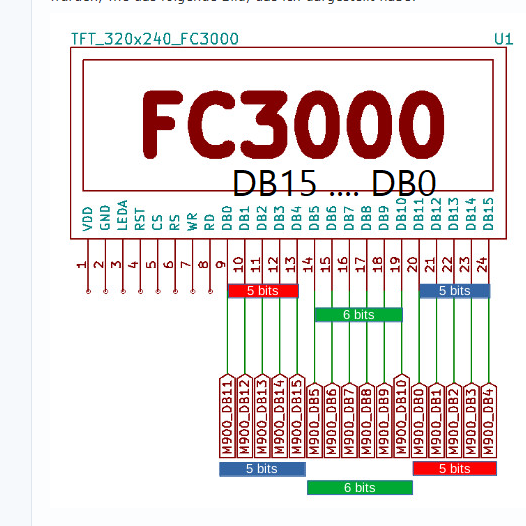
#902 2022-07-02 17:50:05 分享评论
- kendling
- 会员
- 注册时间: 2022-03-04
- 已发帖子: 94
- 积分: 105
Re: 研究FC3000掌機的開源可行性
整理了一下先前抓屏幕初始化资料的过程:https://myvnet.com/p/how-to-use-dla/
自己做一个总结,也方便其他人入门逻辑分析仪的使用。
抓完初始化资料之后曾整理了 2 周,快结束的时候被别的事情拖了一下导致懒癌发作,一直拖到现在才完成。
离线
楼主 #903 2022-07-02 19:42:39 分享评论
#904 2022-07-04 19:35:04 分享评论
- 暗影
- 会员
- 注册时间: 2019-12-24
- 已发帖子: 6
- 积分: 2
Re: 研究FC3000掌機的開源可行性
@司徒 大神你好,我自己做了块板子。烧录pocketgo_od_jckl_no_roms.img这个镜像屏幕正常,我用源码编译出来的屏幕白屏,会是哪方面的原因呢?用github上的镜像串口不能输入,我编译的串口能输入。只编译了内核、源码。
ARCH=arm CROSS_COMPILE=arm-linux- make suniv_defconfig
./run.sh pocketgo
./run.sh /dev/sdb pocketgo
离线
楼主 #905 2022-07-04 20:29:17 分享评论
#906 2022-07-05 09:01:54 分享评论
- 暗影
- 会员
- 注册时间: 2019-12-24
- 已发帖子: 6
- 积分: 2
Re: 研究FC3000掌機的開源可行性
板子丑,要不是想验证下,PCB回来差点直接丢了。
用GitHub镜像启动
用我编译的镜像
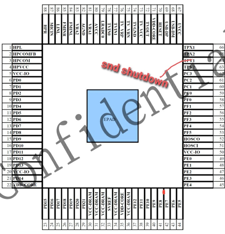
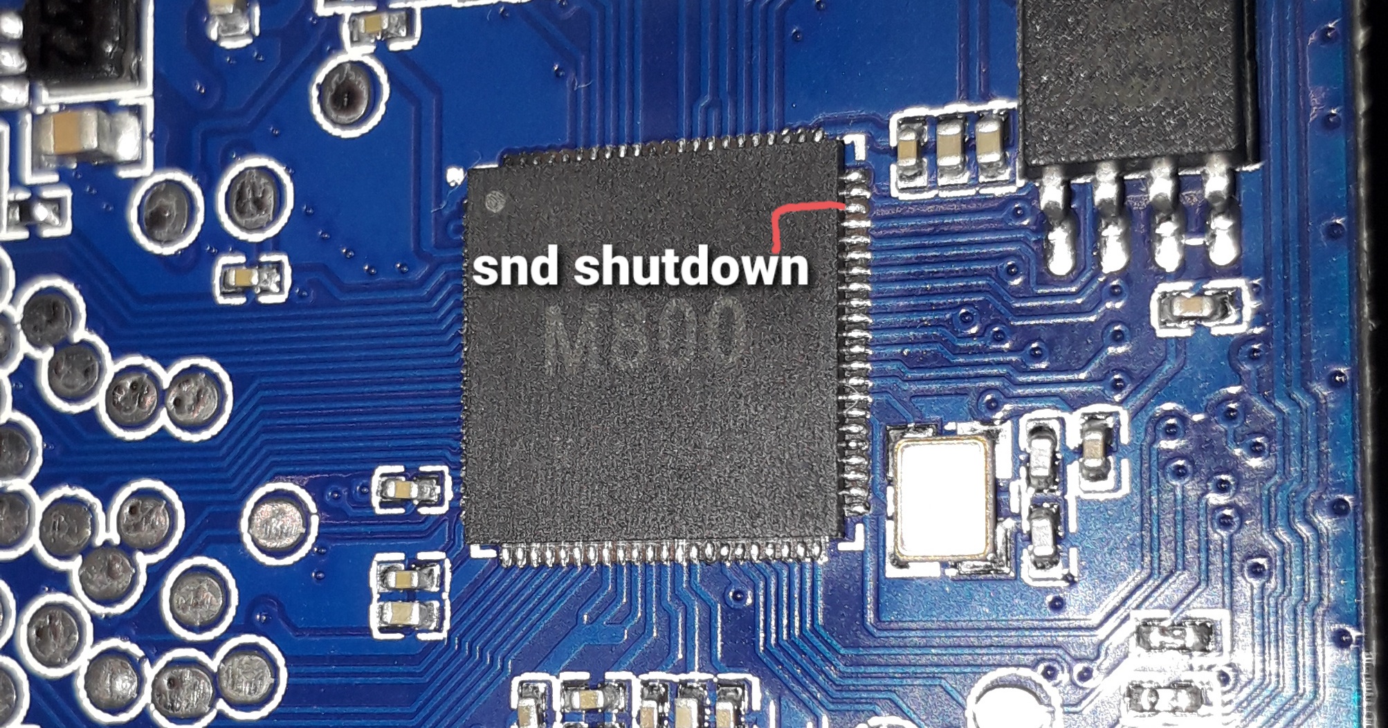
启动log
F1C200S SPL Loader
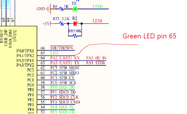
DRAM:156 MHz, 64 MB
Boot: MMC1
[    0.000000] Booting Linux on physical CPU 0x0
[    0.000000] Linux version 4.14.0-vegan (wj@debian) (gcc version 7.3.0 (Buildroot 2018.02.9)) #70 Mon Jul 4 18:49:51 HKT 2022
[    0.000000] CPU: ARM926EJ-S [41069265] revision 5 (ARMv5TEJ), cr=0005317f
[    0.000000] CPU: VIVT data cache, VIVT instruction cache
[    0.000000] OF: fdt: Machine model: allwinner suniv handheld
[    0.000000] Memory policy: Data cache writeback
[    0.000000] random: fast init done
[    0.000000] Built 1 zonelists, mobility grouping on.  Total pages: 16256
[    0.000000] Kernel command line: rootwait root=/dev/mmcblk0p1 ro fstype=vfat init=/mininit -- pocketgo
[    0.000000] suniv model: pocketgo
[    0.000000] PID hash table entries: 256 (order: -2, 1024 bytes)
[    0.000000] Dentry cache hash table entries: 8192 (order: 3, 32768 bytes)
[    0.000000] Inode-cache hash table entries: 4096 (order: 2, 16384 bytes)
[    0.000000] Memory: 61612K/65536K available (2296K kernel code, 103K rwdata, 544K rodata, 112K init, 188K bss, 3924K reserved, 0K cma-reserved)
[    0.000000] Virtual kernel memory layout:
[    0.000000]     vector  : 0xffff0000 - 0xffff1000   (   4 kB)
[    0.000000]     fixmap  : 0xffc00000 - 0xfff00000   (3072 kB)
[    0.000000]     vmalloc : 0xc4800000 - 0xff800000   ( 944 MB)
[    0.000000]     lowmem  : 0xc0000000 - 0xc4000000   (  64 MB)
[    0.000000]     modules : 0xbf000000 - 0xc0000000   (  16 MB)
[    0.000000]       .text : 0xc0008000 - 0xc0246600   (2298 kB)
[    0.000000]       .init : 0xc02d0000 - 0xc02ec000   ( 112 kB)
[    0.000000]       .data : 0xc02ec000 - 0xc0305d00   ( 104 kB)
[    0.000000]        .bss : 0xc0307ce0 - 0xc0336f9c   ( 189 kB)
[    0.000000] NR_IRQS: 16, nr_irqs: 16, preallocated irqs: 16
[    0.000000] clocksource: timer: mask: 0xffffffff max_cycles: 0xffffffff, max_idle_ns: 79635851949 ns
[    0.000000] sched_clock: 32 bits at 100 Hz, resolution 10000000ns, wraps every 21474836475000000ns
[    0.000000] Console: colour dummy device 80x30
[    0.000000] console [tty0] enabled
[    0.070000] Calibrating delay loop... 203.16 BogoMIPS (lpj=1015808)
[    0.070000] pid_max: default: 32768 minimum: 301
[    0.070000] Mount-cache hash table entries: 1024 (order: 0, 4096 bytes)
[    0.070000] Mountpoint-cache hash table entries: 1024 (order: 0, 4096 bytes)
[    0.070000] CPU: Testing write buffer coherency: ok
[    0.070000] Setting up static identity map for 0x80008400 - 0x8000843c
[    0.070000] devtmpfs: initialized
[    0.070000] clocksource: jiffies: mask: 0xffffffff max_cycles: 0xffffffff, max_idle_ns: 19112604462750000 ns
[    0.080000] futex hash table entries: 256 (order: -1, 3072 bytes)
[    0.080000] pinctrl core: initialized pinctrl subsystem
[    0.080000] DMA: preallocated 256 KiB pool for atomic coherent allocations
[    0.090000] SCSI subsystem initialized
[    0.090000] Advanced Linux Sound Architecture Driver Initialized.
[    0.090000] clocksource: Switched to clocksource timer
[    0.120000] workingset: timestamp_bits=30 max_order=14 bucket_order=0
[    0.120000] squashfs: version 4.0 (2009/01/31) Phillip Lougher
[    0.120000] Block layer SCSI generic (bsg) driver version 0.4 loaded (major 252)
[    0.120000] io scheduler noop registered
[    0.120000] io scheduler deadline registered
[    0.120000] io scheduler cfq registered (default)
[    0.120000] io scheduler mq-deadline registered
[    0.120000] io scheduler kyber registered
[    0.130000] suniv-pinctrl 1c20800.pinctrl: initialized sunXi PIO driver
[    0.130000] pwm-backlight backlight: backlight supply power not found, using dummy regulator
[    0.170000] Console: switching to colour frame buffer device 40x30
[    0.180000] Serial: 8250/16550 driver, 4 ports, IRQ sharing disabled
[    0.200000] 1c25400.serial: ttyS1 at MMIO 0x1c25400 (irq = 23, base_baud = 6250000) is a 16550A
[    0.500000] console [ttyS1] enabled
[    0.510000] loop: module loaded
[    0.510000] SCSI Media Changer driver v0.25
[    0.520000] input: suniv-keypad as /devices/virtual/input/input0
[    0.530000] set pocketgo keypad handler
[    0.540000] sunxi-wdt 1c20ca0.watchdog: Watchdog enabled (timeout=16 sec, nowayout=0)
[    0.610000] sunxi-mmc 1c0f000.mmc: base:0xc48f7000 irq:18
[    0.620000] suniv audio driver soc:codec@1c22000: soc:codec@1c22000 <-> soc:codec@1c22000 mapping ok
[    0.640000] ALSA device list:
[    0.640000]   #0: suniv audio card
[    0.650000] Waiting for root device /dev/mmcblk0p1...
[    0.700000] mmc0: host does not support reading read-only switch, assuming write-enable
[    0.710000] mmc0: new SDHC card at address 0001
[    0.720000] mmcblk0: mmc0:0001 SD8GB 7.28 GiB
[    0.730000]  mmcblk0: p1 p2
[    0.770000] VFS: Mounted root (vfat filesystem) readonly on device 179:1.
[    0.780000] devtmpfs: mounted
[    0.790000] Freeing unused kernel memory: 112K
[    0.800000] This architecture does not have kernel memory protection.
[    1.570000] FAT-fs (mmcblk0p2): Volume was not properly unmounted. Some data may be corrupt. Please run fsck.
[    3.270000] Adding 262140k swap on /mnt/.swap.img.  Priority:-2 extents:1 across:262140k SS

Welcome to Miyoo
miyoo login: root
Jun 25 16:33:02 login[31]: root login on 'console'
# top

Mem: 18156K used, 43568K free, 4K shrd, 2780K buff, 9524K cached
CPU:   7% usr   7% sys   0% nic  84% idle   0% io   0% irq   0% sirq
Load average: 0.16 0.03 0.01 1/27 40
  PID  PPID USER     STAT   VSZ %VSZ %CPU COMMAND
   40    31 root     R     1528   2%  15% top
   37    30 root     S     8024  13%   0% ./gmenu2x
   32    30 root     S     2292   4%   0% /usr/bin/daemon
   31     1 root     S     1536   2%   0% -sh
    1     0 root     S     1532   2%   0% init
   30     1 root     S     1532   2%   0% {main} /bin/sh /etc/main
    7     2 root     SW       0   0%   0% [ksoftirqd/0]
   19     2 root     SW       0   0%   0% [mmcqd/0]
   21     2 root     SW<      0   0%   0% [loop0]
   14     2 root     IW       0   0%   0% [kworker/0:1]
   20     2 root     IW<      0   0%   0% [kworker/0:1H]
    8     2 root     SW       0   0%   0% [kdevtmpfs]
    3     2 root     IW       0   0%   0% [kworker/0:0]
    2     0 root     SW       0   0%   0% [kthreadd]
   15     2 root     SW       0   0%   0% [irq/18-sunxi-mm]
    4     2 root     IW<      0   0%   0% [kworker/0:0H]
    5     2 root     IW       0   0%   0% [kworker/u2:0]
   18     2 root     IW       0   0%   0% [kworker/0:2]
    6     2 root     IW<      0   0%   0% [mm_percpu_wq]
   16     2 root     IW       0   0%   0% [kworker/u2:1]
#
附上源文件,KICAD的
F1C2.7z
最近编辑记录 暗影 (2022-07-05 12:29:04)
离线
楼主 #907 2022-07-05 20:40:33 分享评论
#908 2022-07-05 21:03:16 分享评论
- 暗影
- 会员
- 注册时间: 2019-12-24
- 已发帖子: 6
- 积分: 2
Re: 研究FC3000掌機的開源可行性
 。
。
应该是没有了。我手欠改了按键引脚,所以要重新编译。上面图片的最下方有原理图PCB的文件,KICAD5.0的。原理图我转PDF了。Printing 打印原理图.pdf
最近编辑记录 暗影 (2022-07-05 21:19:34)
离线
#909 2022-07-05 22:14:21 分享评论
- 暗影
- 会员
- 注册时间: 2019-12-24
- 已发帖子: 6
- 积分: 2
Re: 研究FC3000掌機的開源可行性
看起来是这样改了,明天试下。
static irqreturn_t lcdc_irq_handler(int irq, void *arg)
{
// if((suniv_variant == 1) || (suniv_variant == 2)){
// flip_lcd(arg);
// }
flip_lcd(arg);
suniv_clrbits(iomm.lcdc + TCON_INT_REG0, (1 << 15));
return IRQ_HANDLED;
}
离线
楼主 #910 2022-07-05 22:46:21 分享评论
Re: 研究FC3000掌機的開源可行性
你修改下如下源代碼, 讓LCD IRQ也可以掃屏試試~
drivers/video/fbdev/sunivfb.c
 370 static irqreturn_t lcdc_irq_handler(int irq, void *arg)
 371 {
 372   //if((suniv_variant == 1) || (suniv_variant == 2)){
 373     flip_lcd(arg);
 374   //}
 375   suniv_clrbits(iomm.lcdc + TCON_INT_REG0, (1 << 15));
 376   return IRQ_HANDLED;
 377 }
离线
#911 2022-07-06 21:44:17 分享评论
- 暗影
- 会员
- 注册时间: 2019-12-24
- 已发帖子: 6
- 积分: 2
Re: 研究FC3000掌機的開源可行性
还是白屏,我烧录能显示的那个镜像,示波器在TE脚上测到了60Hz的信号。开机logo看起来在uboot阶段,我编译的是一直没显示,uboot里没找到显示相关代码。
离线
楼主 #912 2022-07-06 23:20:34 分享评论
#913 2022-07-08 08:58:31 分享评论
- 暗影
- 会员
- 注册时间: 2019-12-24
- 已发帖子: 6
- 积分: 2
Re: 研究FC3000掌機的開源可行性
好的,谢谢。
离线
#914 2022-07-08 21:23:31 分享评论
- cch2001
- 会员
- 注册时间: 2022-07-08
- 已发帖子: 1
- 积分: 1
Re: 研究FC3000掌機的開源可行性
小弟想上來發問, 小橫米跟FC3000幾乎相同,但FC3000上的FBA A320卻無法按熱鍵跳出遊戲,有爬文在前面司徒兄有提到要重新編譯,但小弟對這個不太懂,除了重新編譯以外還有其他方法嗎?感謝各位
离线
楼主 #915 2022-07-09 20:09:11 分享评论
#916 2022-07-14 23:00:23 分享评论
- alex3325
- 会员
- 注册时间: 2022-07-14
- 已发帖子: 1
- 积分: 1
Re: 研究FC3000掌機的開源可行性
司徒兄,想請教一下有沒有FC3000 IPS版V1刷V2的映像檔,上面的文只有TFT版的,我下載後放入記憶卡開機只有黑畫面,謝謝
离线
楼主 #917 2022-08-07 10:13:34 分享评论
#918 2022-08-19 18:37:09 分享评论
- neotendo
- 会员
- 注册时间: 2022-08-19
- 已发帖子: 180
- 积分: 203
Re: 研究FC3000掌機的開源可行性
hi there, i have bricked my v1 old version, was trying to dump the stock rom but used a flasher image instead.
does anybody have the stock rom from the v1 old version (M800 cpu, tft t2812-m106-24c-7d) or can anyone point me in a direction to port the linux to this device?
thank you very much
离线
#919 2022-08-19 19:03:58 分享评论
- neotendo
- 会员
- 注册时间: 2022-08-19
- 已发帖子: 180
- 积分: 203
Re: 研究FC3000掌機的開源可行性
@司徒 最近入了一个 FC3000 V2, 说是 IPS 屏,拆机发现屏的型号是 T2812-M106-024C-7D , 网上查得驱动 IC 型号为 HX8347, 不知是否对你有帮助
i have the same model, my cpu is M800 and i bricked mine, i need help, the stock v1 rom or how i can port the linux over
离线
楼主 #920 2022-08-20 12:40:03 分享评论
Re: 研究FC3000掌機的開源可行性
@neotendo
Q1: does anybody have the stock rom from the v1 old version ?
A1: As I known, we don't have such backup rom for you to restore your device back to normal. If you can find someone has the model as yours, I can provide dump progam to you and then you can try to dump it. I think this is what we can help on.
Q2: can anyone point me in a direction to port the linux to this device ?
A2: Sure, we can. But before porting Linux into your device, you need known which LCD model is used in your device.
So, what is your next step ?
离线
#921 2022-08-22 18:24:10 分享评论
- neotendo
- 会员
- 注册时间: 2022-08-19
- 已发帖子: 180
- 积分: 203
Re: 研究FC3000掌機的開源可行性
@Situ
A1: Thank you very much, maybe i can find someone with the same model, a dump tool would be handy.
A2: my device has an tft display i think (T2812-M106-24C-7D, maybe an HX8347 driver) cpu is M800.
i would be very grateful if you would help me there at least to have linux on it
thank you
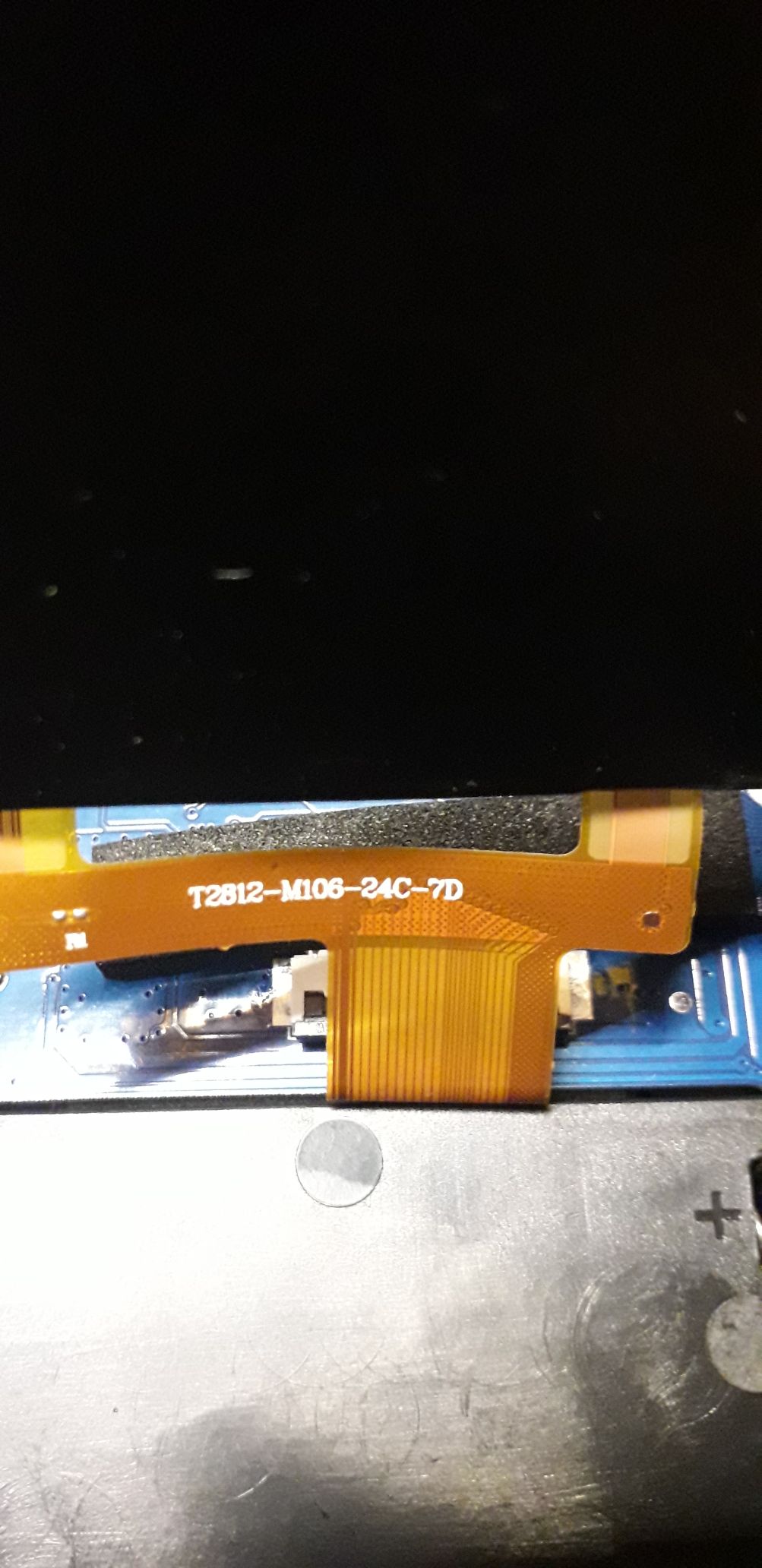
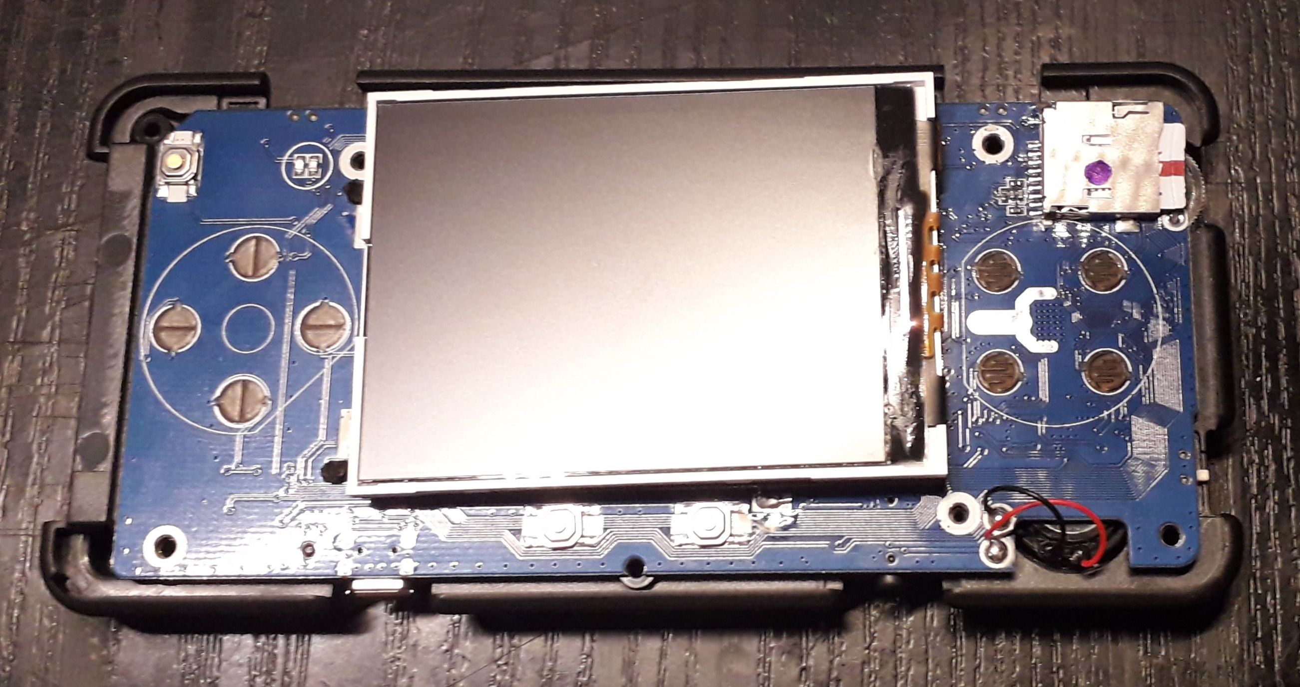
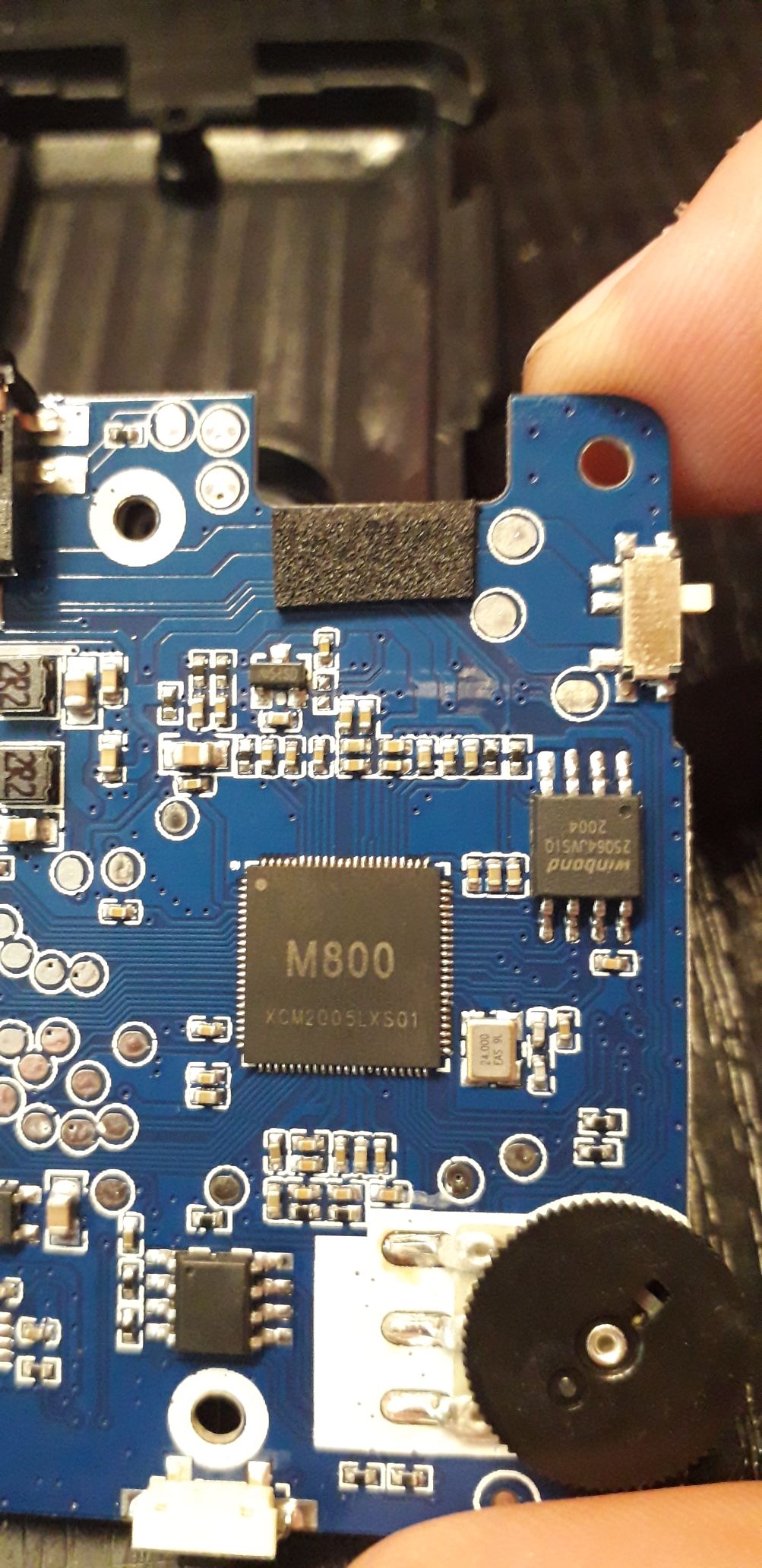
最近编辑记录 neotendo (2022-08-22 18:28:52)
离线
#922 2022-08-22 19:47:28 分享评论
- hox
- 会员
- 注册时间: 2020-02-17
- 已发帖子: 46
- 积分: 34.5
Re: 研究FC3000掌機的開源可行性
@neotendo
I have same model but already bricks by mistake, just drop it.
sorry can't help you
离线
#923 2022-08-22 21:02:02 分享评论
- neotendo
- 会员
- 注册时间: 2022-08-19
- 已发帖子: 180
- 积分: 203
Re: 研究FC3000掌機的開源可行性
@Hox
Yes, I saw it, that's why I didn't even ask you. I accidentally bricked mine too. I thought I started a dump program, but then it was an ips flasher. I hope that I can at least get linux running on it through situ before I throw it away
离线
楼主 #924 2022-08-22 21:35:53 分享评论
Re: 研究FC3000掌機的開源可行性
@neotendo
[Q1] Thank you very much, maybe i can find someone with the same model, a dump tool would be handy.
[A1]
Here is the dump tool you can use to dump firmware from another FC3000:
https://github.com/steward-fu/fc3000/releases/download/v1.0/ips_fc3000_dump_0627_1.img.7z
Step 1: extract ips_fc3000_dump_0627_1.img.7z
Step 2: flash image into MicroSD as the following command
$ sudo dd if=ips_fc3000_dump_0627_1.img of=/dev/sdX bs=1MStep 3: put this MicroSD into another FC3000 and then power on
Step 4: wait for 10 minutes and then power off
Step 5: provide v1rom.img back to me and I will create restore tool for you
[Q2] i would be very grateful if you would help me there at least to have linux on it
[A2]
It is easy for you to port Linux OS into your FC3000 if leverage existing source code.
So, here is what you need: https://github.com/steward-fu/fc3000
Preparation
Step 1: make sure your development environment is ready
Step 2: download https://github.com/steward-fu/fc3000/releases/download/v1.0/fc3000_ips_od_jutleys_no_roms.img.7z
Step 3: extract fc3000_ips_od_jutleys_no_roms.img.7z and then flash into MicroSD
Step 4: build kernel source code (kernel.tar.gz) without any problem
Step 5: build uboot source code (uboot.tar.gz) without any problem
Step 6: put MicroSD into your FC3000 and then power on
Step 7: when boot into Linux OS, you can hear a beep sound from speaker
Step 8: make sure all of steps as described above are ready and then you can go to next step
Porting LCD driver for Linux OS
Step 1: update initial code for HX8347 panel, kernel source code: kernel/drivers/video/fbdev/sunivfb.c
593 static void fc3000_lcd_init(void)Since we guess the LCD panel is HX8347, so, we need try example code to see whether it works or not.
Here is the example code we can use: https://os.mbed.com/users/Suky/code/LCDTFT//file/1085b6177f6e/LCDTFT.cpp
If it does not work, you need google it and then try different example code.
Such method we use is more like black box testing.
Step 2: build modified kernel source
Step 3: build uboot source code (in this step, kernel and uboot images will be updated into MicroSD)
Step 4: put MicroSD into your FC3000 and then power on
Step 5: if the LCD is still blank, go back to Step 1
Here are the steps I wrote for your referece to port Linux OS into your FC3000.
I cannot make sure whether it is clear or not.
If not, it is welcome to post your question.
离线
#925 2022-08-23 01:27:42 分享评论
- neotendo
- 会员
- 注册时间: 2022-08-19
- 已发帖子: 180
- 积分: 203
Re: 研究FC3000掌機的開源可行性
@Situ
Thank you very much, I'll try that. Had already tried to compile that yesterday, but I had errors in the gdb compilation.
离线
#926 2022-08-23 05:36:23 分享评论
- neotendo
- 会员
- 注册时间: 2022-08-19
- 已发帖子: 180
- 积分: 203
Re: 研究FC3000掌機的開源可行性
@Situ
fc3000 starts with a white screen now. is that right?
最近编辑记录 neotendo (2022-08-23 05:39:40)
离线
#927 2022-08-23 09:56:16 分享评论
- hox
- 会员
- 注册时间: 2020-02-17
- 已发帖子: 46
- 积分: 34.5
Re: 研究FC3000掌機的開源可行性
@Situ
fc3000 starts with a white screen now. is that right?
here is website i found about screen, (https://www.skytech.ir/product_details.aspx?ID_Parts=4919&T2812-m106-24c-7d-2.8inch-lcd-tft-hx8347-driver)
i can't open it, hope this could help you
离线
#928 2022-08-23 11:19:17 分享评论
- neotendo
- 会员
- 注册时间: 2022-08-19
- 已发帖子: 180
- 积分: 203
Re: 研究FC3000掌機的開源可行性
@Hox
Thank you
Here some more informations
https://www.ramtex.dk/display-controller-driver/rgb/hx8347.htm
离线
楼主 #929 2022-08-23 12:25:43 分享评论
#930 2022-08-23 12:35:48 分享评论
- neotendo
- 会员
- 注册时间: 2022-08-19
- 已发帖子: 180
- 积分: 203
Re: 研究FC3000掌機的開源可行性
@Situ
ps: i do not hear any sound when booting linux
I don't know. Maybe an older V1 version. As my mcu is an M800 and not M900.
SPI flash is on the other side

最近编辑记录 neotendo (2022-08-23 13:10:42)
离线
楼主 #931 2022-08-23 13:38:34 分享评论
#932 2022-08-23 13:51:22 分享评论
- neotendo
- 会员
- 注册时间: 2022-08-19
- 已发帖子: 180
- 积分: 203
Re: 研究FC3000掌機的開源可行性
@Situ
Thank you so much <3
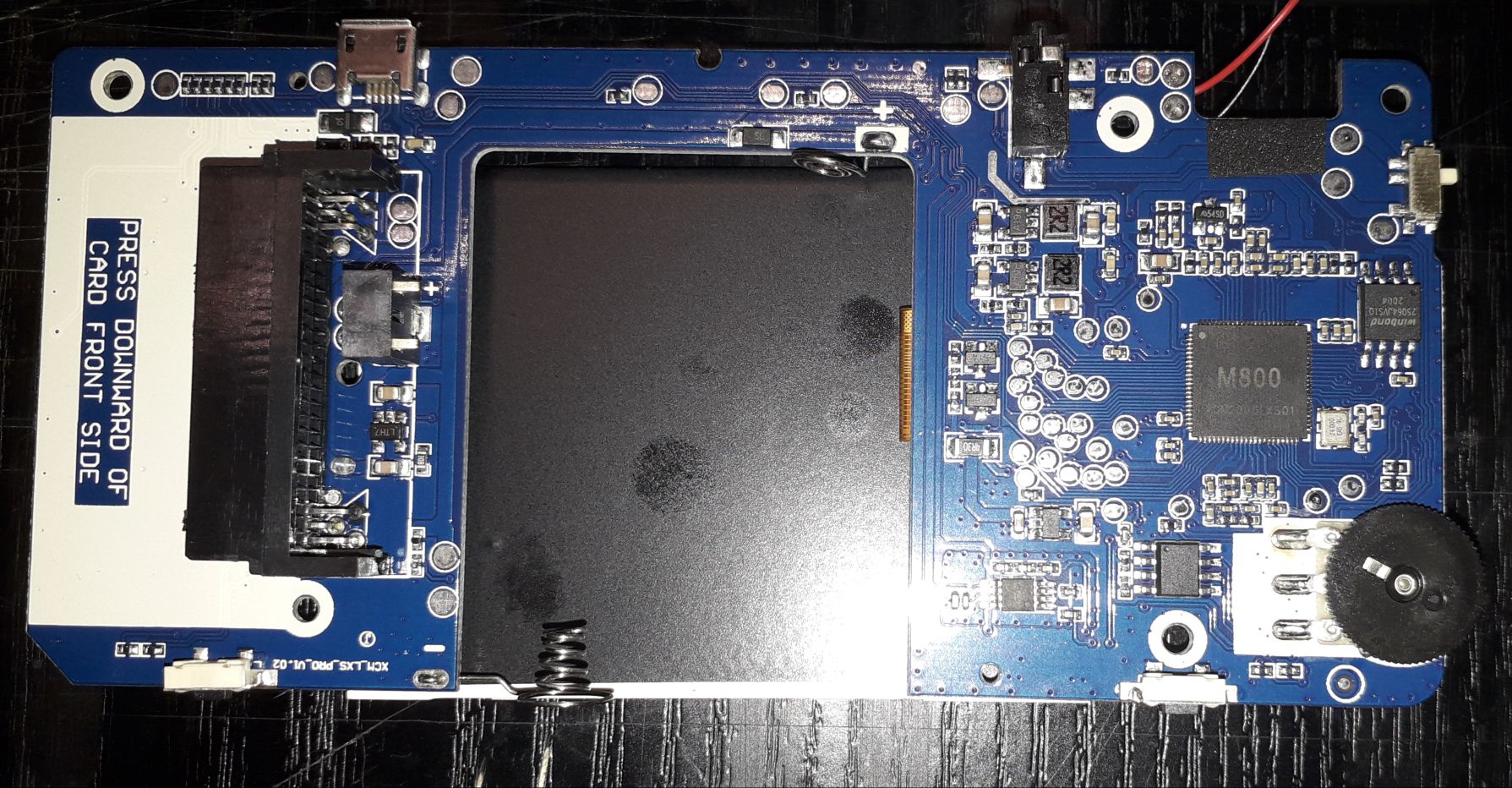
离线
楼主 #933 2022-08-23 20:52:15 分享评论
Re: 研究FC3000掌機的開源可行性
@neotendo
[Q1] Had already tried to compile that yesterday, but I had errors in the gdb compilation.
[A1] Please post error logs if need help.
[Q2] fc3000 starts with a white screen now. is that right?
[A2] Yes, it means your FC3000 is bootig from MicroSD.
[Q3] i do not hear any sound when booting linux
[A3] Basically, it is a noise when turn on speaker.
According to the image you posted, it seems your FC3000 is more older than ours.
I guess some of LCD pinouts may be different with our FC3000.
Except for pinout changed, I am afraid that the LCD panel on your FC3000 is not HX8347.
So, it is not easy for us to port Linux OS into your FC3000 beacuse of many unknown information.
But we can try our best to see whether it is possible or not.
I spent some time to collect initial code from google for your FC3000 as possible.
Here are the lists I would like to test on your FC3000:
1. https://os.mbed.com/users/Suky/code/LCDTFT//file/1085b6177f6e/LCDTFT.cpp
2. https://searchcode.com/codesearch/view/46088261/
3. https://steward-fu.github.io/website/handheld/q8/asm_lcd_gpio.htm
4. https://whycan.com/t_6647.html#p64598
5. https://whycan.com/t_6647.html#p64694
6. https://www.microchip.com/forums/m624935.aspx
7. https://github.com/CariadDisplayLibrary/HX8347D/blob/master/src/HX8347D.cpp
All of them are compiled and packed as flash image files.
So, you just need flash them into your MicroSD and then test it on your FC3000.
Source code: https://github.com/steward-fu/fc3000/releases/download/source/lcd_panel_identify_src.zip
Flash image: https://github.com/steward-fu/fc3000/releases/download/v1.0/lcd_panel_identify_img.zip
SHA1
beb68550727732fe80b8f5083463df0e5f2996d8  test_1.img
3d4d309a1111e6cc813de2dfba485a7888ad67eb  test_2.img
57de59c85e1cca75983c1a1dc5283444137b4e76  test_3.img
dbef7df5b042f95398c8e7ff3d7188ec7a57a47c  test_4.img
47fa196756b54ee022ae305a81fe7dc200ccb727  test_5.img
e9efbfd13c8c508e7a392ce20bbb7e1dc79f1e2b  test_6.img
f7a49d1ea656d7df7800b4bec202d4e60a98fab8  test_7.img
How to test (test_1.img ~ test_7.img):
Step 1: flash test_x.img into MicroSD as the following command
$ sudo dd if=test_x.img of=/dev/sdX bs=1MStep 2: put MicroSD into FC3000 and then power on
Step 3: if the initial code is correct, your FC3000 should look like this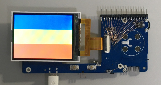
离线
#934 2022-08-23 21:34:49 分享评论
- neotendo
- 会员
- 注册时间: 2022-08-19
- 已发帖子: 180
- 积分: 203
Re: 研究FC3000掌機的開源可行性
@Situ
was able now to compile it. gcc version 8 and higher has a problem with null pointer strings, i had to change 2 lines in gdbusmessage.c and gdbusauth.c
why do you think it's not hx8347?
thanks <3,you are a master, i will try the images now
最近编辑记录 neotendo (2022-08-23 22:50:36)
离线
#935 2022-08-23 21:54:41 分享评论
- neotendo
- 会员
- 注册时间: 2022-08-19
- 已发帖子: 180
- 积分: 203
Re: 研究FC3000掌機的開源可行性
@Situ
None of the images gives color on screen, boots only in white (backlight) screen.
as you mentioned it before, another driver or pinout i guess
最近编辑记录 neotendo (2022-08-23 21:57:09)
离线
#936 2022-08-23 22:35:42 分享评论
- neotendo
- 会员
- 注册时间: 2022-08-19
- 已发帖子: 180
- 积分: 203
Re: 研究FC3000掌機的開源可行性
@Situ
Here are some photos from the display and connector, maybe you can use it
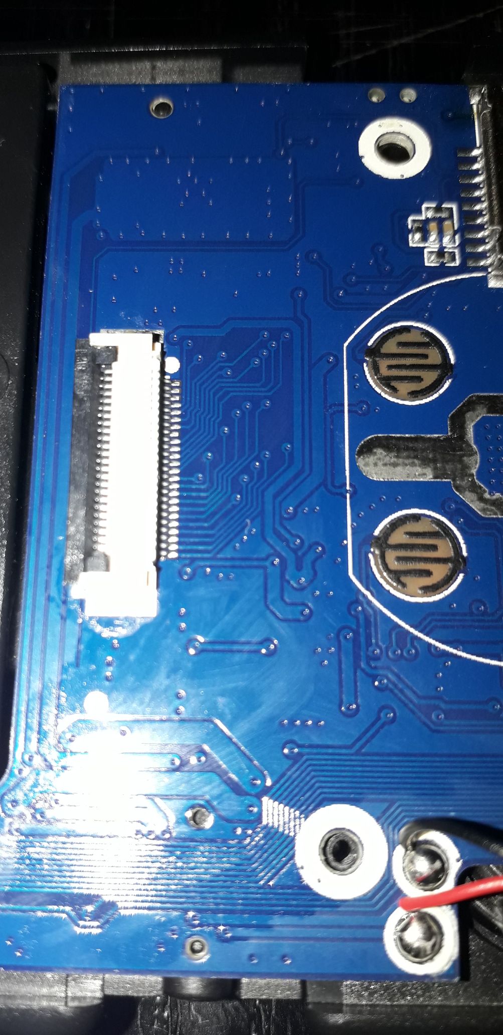
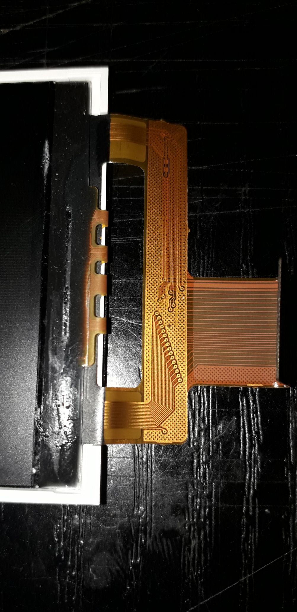
离线
#937 2022-08-24 04:19:32 分享评论
- neotendo
- 会员
- 注册时间: 2022-08-19
- 已发帖子: 180
- 积分: 203
Re: 研究FC3000掌機的開源可行性
@Situ
i checked our displays, both connections look similar but mirrored somehow (different pinout?)
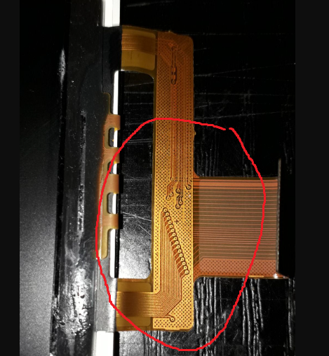

最近编辑记录 neotendo (2022-08-24 04:20:12)
离线
楼主 #938 2022-08-24 10:57:26 分享评论
楼主 #939 2022-08-24 13:31:07 分享评论
Re: 研究FC3000掌機的開源可行性
@neotendo
[Q1] why do you think it's not hx8347?
[A1] In my experiences, ST-xxxx, GC-xxxx, ILI-xxxx series are more commonly used in inexpensive handheld.
Thanks for your information.
If I understood correctly, it seems the bus of R and B are swapped from F1C100S side as the following image I depicted:
Here is link for all of the LCD pinouts (TFT FC3000):
https://steward-fu.github.io/website/handheld/fc3000/lcd_init.htm
It is worthy to try this idea on your FC3000.
I will prepare testing images for your FC3000 later on.
Please wait for update.
离线
楼主 #940 2022-08-24 17:06:58 分享评论
Re: 研究FC3000掌機的開源可行性
@neotendo
Here is testing file (test_1.img ~ test_8.img):
https://github.com/steward-fu/fc3000/releases/download/v1.0/lcd_panel_identify_swap_img.zip
SHA1
f18644f790e4b2ccd6cc55ce161b8661e369ed42  test_1.img
f51dc6390855e26676f9f0564cc9b8f6b7ffa57e  test_2.img
65c541eb2e3aa9807cacf99dd6b0a7a3f56ea531  test_3.img
7df42ceb8cfec7b421980b7544a8481ed83d8b9a  test_4.img
93ffd00c223166149afa91c835e90be12a5ab3b4  test_5.img
6f3e295018b2aa3a363ca169510327e294c17afa  test_6.img
59df3d8467e044ee725a200522ff52ec1c59e466  test_7.img
c4dddb1afb0cfe5ffd7450e84c524a10caa3062b  test_8.img
离线
#941 2022-08-24 17:53:30 分享评论
- neotendo
- 会员
- 注册时间: 2022-08-19
- 已发帖子: 180
- 积分: 203
Re: 研究FC3000掌機的開源可行性
@Situ
if R and B are swapped, shouldn't it just be wrong colors?
i try your test files now
最近编辑记录 neotendo (2022-08-24 18:13:06)
离线
#942 2022-08-24 18:10:50 分享评论
- neotendo
- 会员
- 注册时间: 2022-08-19
- 已发帖子: 180
- 积分: 203
Re: 研究FC3000掌機的開源可行性
@Situ
something new my brother.
all test files shows white screen, only test_6 and test_7 are different, they showed a colored "snow" image
ps:the sound from the video comes from the power switch (not speaker)
TEST_6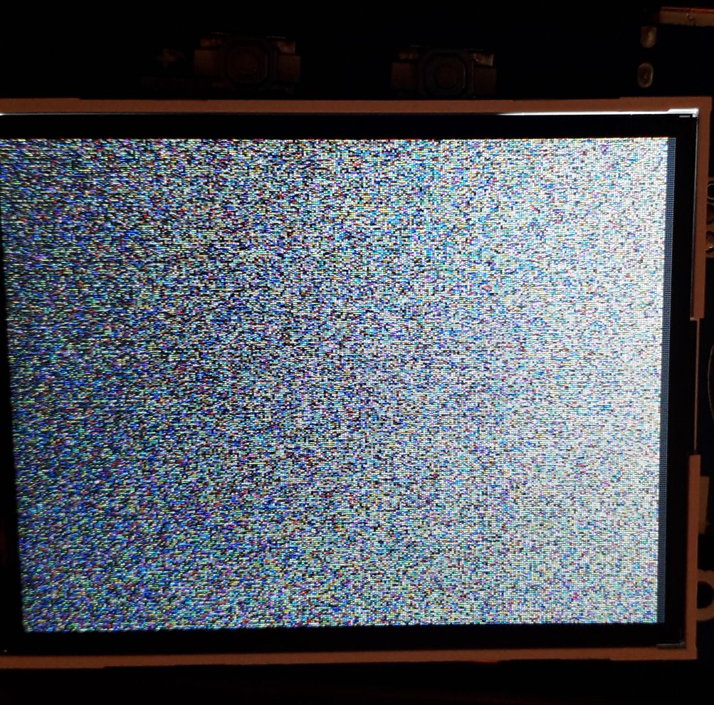
TEST_7
最近编辑记录 neotendo (2022-08-24 18:14:48)
离线
#943 2022-08-24 18:26:04 分享评论
- neotendo
- 会员
- 注册时间: 2022-08-19
- 已发帖子: 180
- 积分: 203
Re: 研究FC3000掌機的開源可行性
neotendo 说:@Situ
fc3000 starts with a white screen now. is that right?
here is website i found about screen, (https://www.skytech.ir/product_details.aspx?ID_Parts=4919&T2812-m106-24c-7d-2.8inch-lcd-tft-hx8347-driver)
i can't open it, hope this could help you
thank you very much, unfortunately there is no information or downloads on their site, I wrote via the contact link, let's see.
离线
楼主 #944 2022-08-24 19:07:56 分享评论
Re: 研究FC3000掌機的開源可行性
@neotendo
[Q1] if R and B are swapped, shouldn't it just be wrong colors?
[A1]
For i80 interface, there is a MCU embedded in LCD panel, which is in charge of rendering color on LCD.
Before MCU gets started, we need to initialize this MCU firstly, ex: voltage, gamma, frame rate and so on.
So, this is why we need initial code to initialize LCD panel.
If the bus of R and B are swapped, the MCU cannot be initialized properly due to invalid initial sequence.
It means MCU cannot work properly, just like "snow" screen as your testing.
I have to think what of testing we can use.
If you have any suggestion or idea, it is very welcome.
离线
#945 2022-08-24 20:25:39 分享评论
- neotendo
- 会员
- 注册时间: 2022-08-19
- 已发帖子: 180
- 积分: 203
Re: 研究FC3000掌機的開源可行性
@司徒
right, of course. silly me. the data runs naturally over this bus. I'm excited, seems like we're on the right track.
many thanks for your effort
ps: i know much about electronics, i know that the hx8347 for example is an mcu, i simply forgotten some logic in my brain, hahaha
I would work with the test_6 source code, test_7 seems to do something different somehow. did you program the "snow" like this or should it be 3 color bars?
最近编辑记录 neotendo (2022-08-24 20:34:50)
离线
楼主 #946 2022-08-24 20:45:15 分享评论
Re: 研究FC3000掌機的開源可行性
@neotendo
I guess it should miss write command (0x2c), which is used to tell MCU we can start to write data into memory.
So, the screen you posted is like the following one: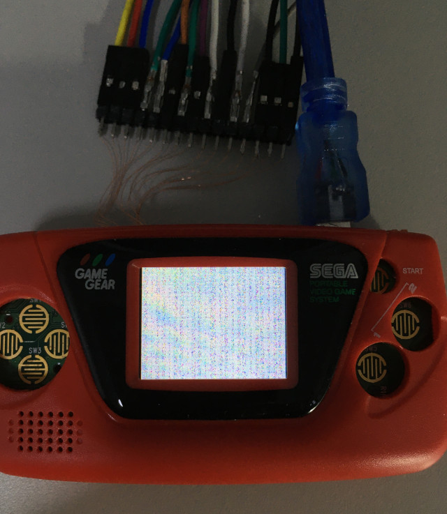
Here is the modified test_6 for your testing (append 0x2c at the end of code):
test_6.img.zip
SHA1:
b530ea20039c5ed7dd695f3ee9bd2228275a4fca test_6.img离线
#947 2022-08-24 20:49:40 分享评论
- neotendo
- 会员
- 注册时间: 2022-08-19
- 已发帖子: 180
- 积分: 203
Re: 研究FC3000掌機的開源可行性
@司徒
result: colored "snow/noise"
离线
楼主 #948 2022-08-24 20:51:56 分享评论
#949 2022-08-24 20:59:50 分享评论
- neotendo
- 会员
- 注册时间: 2022-08-19
- 已发帖子: 180
- 积分: 203
Re: 研究FC3000掌機的開源可行性
@司徒
How about reversing the pins from DB0-DB15 left to right -> DB15-DB0 left to right? (your FC3000 diagram: so DB0 starts from the right then)
i think RST,CS,RS,WR,RD are ok else we would see nothing
最近编辑记录 neotendo (2022-08-24 21:05:53)
离线
#950 2022-08-24 23:19:52 分享评论
- hox
- 会员
- 注册时间: 2020-02-17
- 已发帖子: 46
- 积分: 34.5
Re: 研究FC3000掌機的開源可行性
@司徒
How about reversing the pins from DB0-DB15 left to right -> DB15-DB0 left to right? (your FC3000 diagram: so DB0 starts from the right then)
i think RST,CS,RS,WR,RD are ok else we would see nothing
https://whycan.com/files/members/10141/Screenshot%202022-08-24%20150026.png
glad to see you making progress,I have 500M/32 Channel logic analysis. unfortunately my fc3000 bricking after arrival in one hours. or i could help hack it,
PS: i try to flash firmware without read notice first, try to fix it but my baby cost all my free time, so just drop it.
离线
楼主 #951 2022-08-24 23:55:27 分享评论
Re: 研究FC3000掌機的開源可行性
@neotendo
Here is the testing file (swap R-B and then reverse DB0-DB15):
https://github.com/steward-fu/fc3000/releases/download/v1.0/lcd_panel_identify_swap-1_img.zip
SHA1
3a1e957291d36ff5302f30dcb54dcb54aec79063  test_1.img
6b4ffd2e876c1fae617482ed52147b46e537c884  test_2.img
b1ad9914b93e1262820c028e631dc315f10caf06  test_3.img
83749d860e9642d5b3b8f3c6082d3b501d95b111  test_4.img
d744e25906877e2c30da15694e2ca24d3a52e53f  test_5.img
459bf12908d91cc3ebe22338cccbbbc20eda9d0b  test_6.img
1ff27922d41d53c479bef6d6f220d868f36ed6b0  test_7.img
离线
#952 2022-08-25 00:00:20 分享评论
- neotendo
- 会员
- 注册时间: 2022-08-19
- 已发帖子: 180
- 积分: 203
Re: 研究FC3000掌機的開源可行性
@hox
thank you very much
Unfortunately I don't have a logic analyzer. it was the same for me, I read that I can make my v1 a v2, then I thought that I would start a dump program, but unfortunately it was an ips flasher. nothing is possible without stock old v1. apart from what Situ and I try, we can't do anything else for the device. unless someone has the same old v1 and would dump the rom
keep your device if you still have it, maybe we can run situ's linux on them later
最近编辑记录 neotendo (2022-08-25 00:00:44)
离线
#953 2022-08-25 00:08:42 分享评论
- neotendo
- 会员
- 注册时间: 2022-08-19
- 已发帖子: 180
- 积分: 203
Re: 研究FC3000掌機的開源可行性
@司徒
you are awesome,
but sorry, nothing. all images show white screen.
Except for these DB15...DB0 images swapping R and B again, I wouldn't think of anything now either
最近编辑记录 neotendo (2022-08-25 00:10:18)
离线
楼主 #954 2022-08-25 10:58:06 分享评论
Re: 研究FC3000掌機的開源可行性
@neotendo
Here is the another idea for testing as the following image: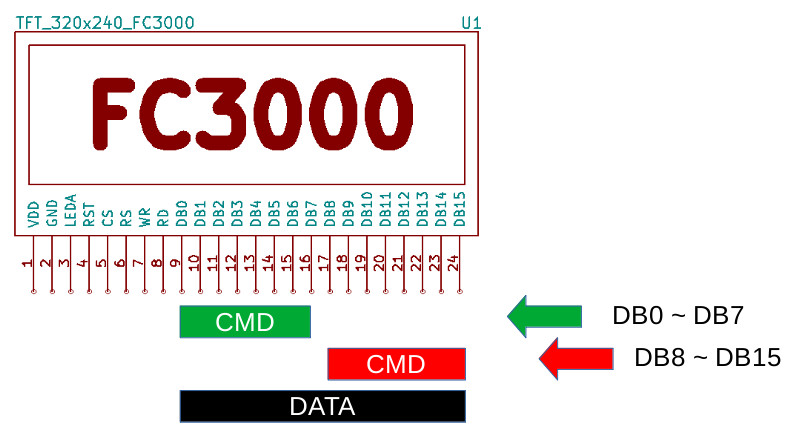
For i80 interface, there are 2 methods used to send command, which are DB0~DB7 and DB8~DB15 respectively.
In our previous testing, we focused on DB0~DB7 bus for command.
It is time to test another testing to see whether it works or not.
Here is the download link for testing (swap R-B and send command via DB8~DB15):
https://github.com/steward-fu/fc3000/releases/download/v1.0/lcd_panel_identify_swap-2_img.zip
SHA1
2ed14db691ad2add6257ef450cc003819e0708ad  test_1.img
f119dcd0328bf34114f969234477624252e8e30b  test_2.img
c8a20326a5896045f73e124d96d68ec0b4d534db  test_3.img
27d85a6b8f2408fc507e8e2a37cab78b0d4401c1  test_4.img
8f586266ad2b3b19b18bf9bbf738495884537f9f  test_5.img
01753ae90098cec8992732107fb3ef0f50c30063  test_6.img
88bf176e7bafc24e5f857d581a7982c5e7f9535a  test_7.img
离线
#955 2022-08-25 12:36:05 分享评论
- neotendo
- 会员
- 注册时间: 2022-08-19
- 已发帖子: 180
- 积分: 203
Re: 研究FC3000掌機的開源可行性
@司徒
again, nothing , all white / only backlight
ps: i did it!!! took your test_6 with the "snow" and added command 0x22 at the end of init
(cmd 0x22, write sram, hx8347)
main.s.txt
pps: test_7.s works also, added ldr r0, =0x22(bl lcd_cmd) at the end of init
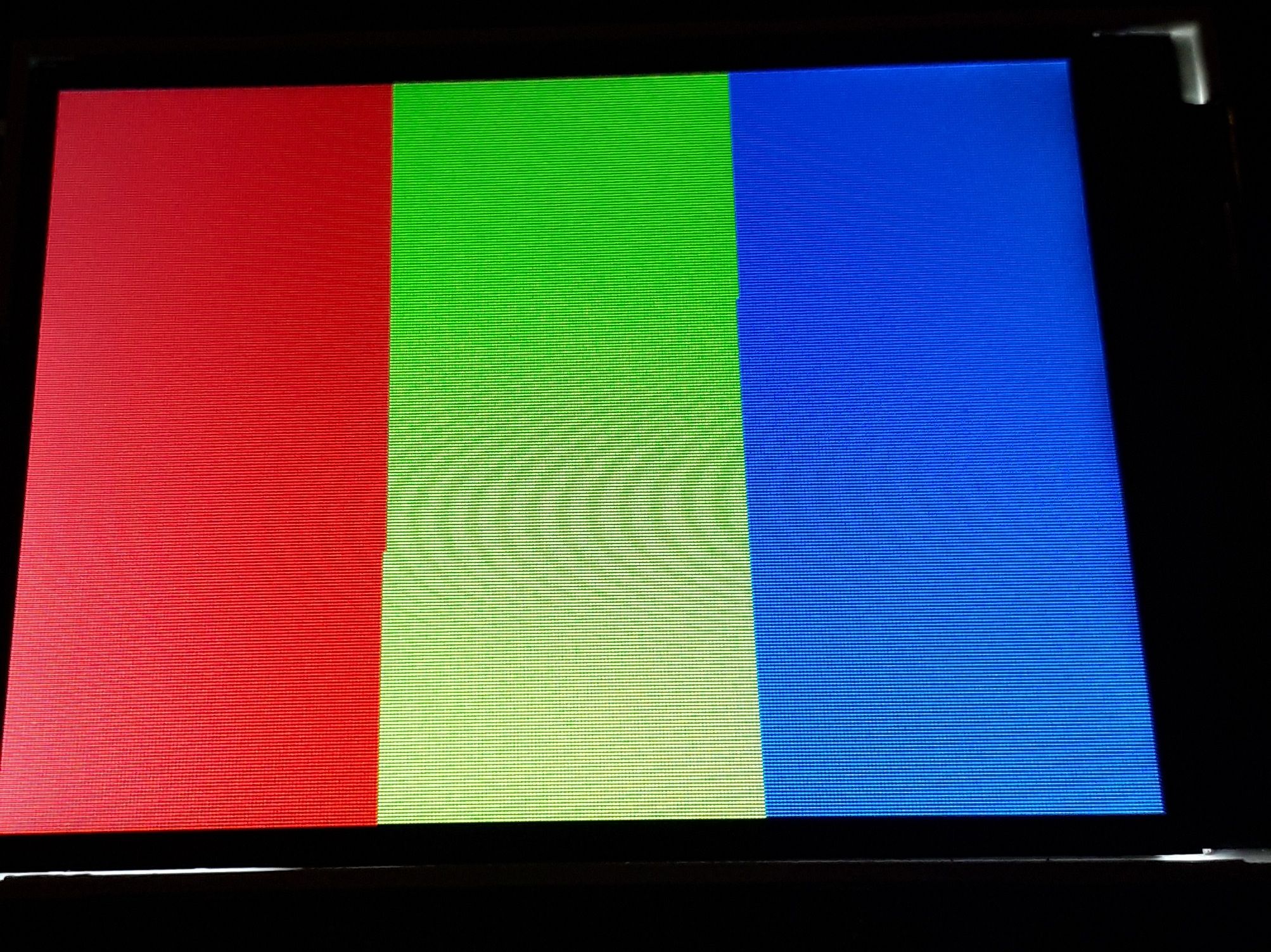
最近编辑记录 neotendo (2022-08-25 13:39:13)
离线
#956 2022-08-25 14:41:29 分享评论
- neotendo
- 会员
- 注册时间: 2022-08-19
- 已发帖子: 180
- 积分: 203
Re: 研究FC3000掌機的開源可行性
@Situ
screen orientation seems wrong. your display starts from top with color blue, my display starts with red color from left
pps: switched the mode from RGB to BGR and changed MX,MY,ML (cmd 0x16, dat 0x20), changed window area
i think we can shorten the init routine, looks to much, but atleast we have some good results
used datasheets
HX8347-D_Himax.pdf
HX8347.pdf
最近编辑记录 neotendo (2022-08-25 16:08:04)
离线
楼主 #957 2022-08-25 16:06:44 分享评论
#958 2022-08-25 16:11:17 分享评论
- neotendo
- 会员
- 注册时间: 2022-08-19
- 已发帖子: 180
- 积分: 203
Re: 研究FC3000掌機的開源可行性
@neotendo
Congratulations !
Thank you so much! what do you think, could you do something on the linux kernel now?
离线
楼主 #959 2022-08-25 17:42:10 分享评论
#960 2022-08-25 17:54:14 分享评论
- neotendo
- 会员
- 注册时间: 2022-08-19
- 已发帖子: 180
- 积分: 203
Re: 研究FC3000掌機的開源可行性
@neotendo
Since I have stopped maintaining FC3000 some time ago, it is recommended to port by yourself.
If you need help or suffer from problem, it is welcome to post your question.
I don't think I'll be able to do it, I have no idea where to start or which files to change.
I have no idea how and where I swap R and B, for example.
离线
#961 2022-08-25 19:44:48 分享评论
- neotendo
- 会员
- 注册时间: 2022-08-19
- 已发帖子: 180
- 积分: 203
Re: 研究FC3000掌機的開源可行性
@Situ
can you convert the lcd_wr assembler routine to c#? i am not able to convert assembler to c#.
i think i have to modify sunivfb.c and lcdc.h atleast
i will try the reset routine by my self, it is hard for me either, hahaha
最近编辑记录 neotendo (2022-08-25 19:47:22)
离线
楼主 #962 2022-08-25 21:03:07 分享评论
Re: 研究FC3000掌機的開源可行性
@neotendo
T2812-M106-24C-7D_HX8347.zip
sunivfb.c: replaced initial code as hx8347 (based on your previous file) for fc3000
sunivfb_hx8347.patch: patch file for hx8347
For your requirement, just update sunivfb.c file and then rebuild kernel and uboot.
I think it is time to run Linux OS on your FC3000.
Ref: https://github.com/steward-fu/fc3000
离线
#963 2022-08-25 23:42:18 分享评论
- neotendo
- 会员
- 注册时间: 2022-08-19
- 已发帖子: 180
- 积分: 203
Re: 研究FC3000掌機的開源可行性
@司徒
IT'S ALIVE!!!
But it seems this hardware is much different then yours...
- sound not working
- most buttons not working
- colors wrong (ps: i only updated uboot atm, device is not booting with my rootfs and mininit)
- green power led not working
atleast fc3000 is running your linux image
thank you very much for your help <3
ps: is it possible to inject the new lcd code into an stock v1 or v2 rom?
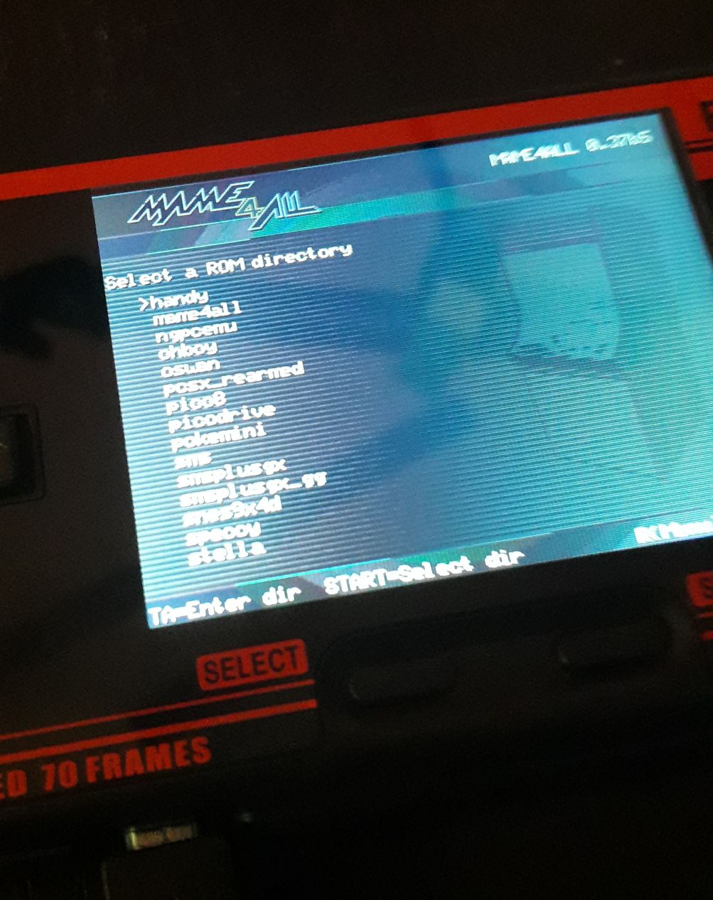
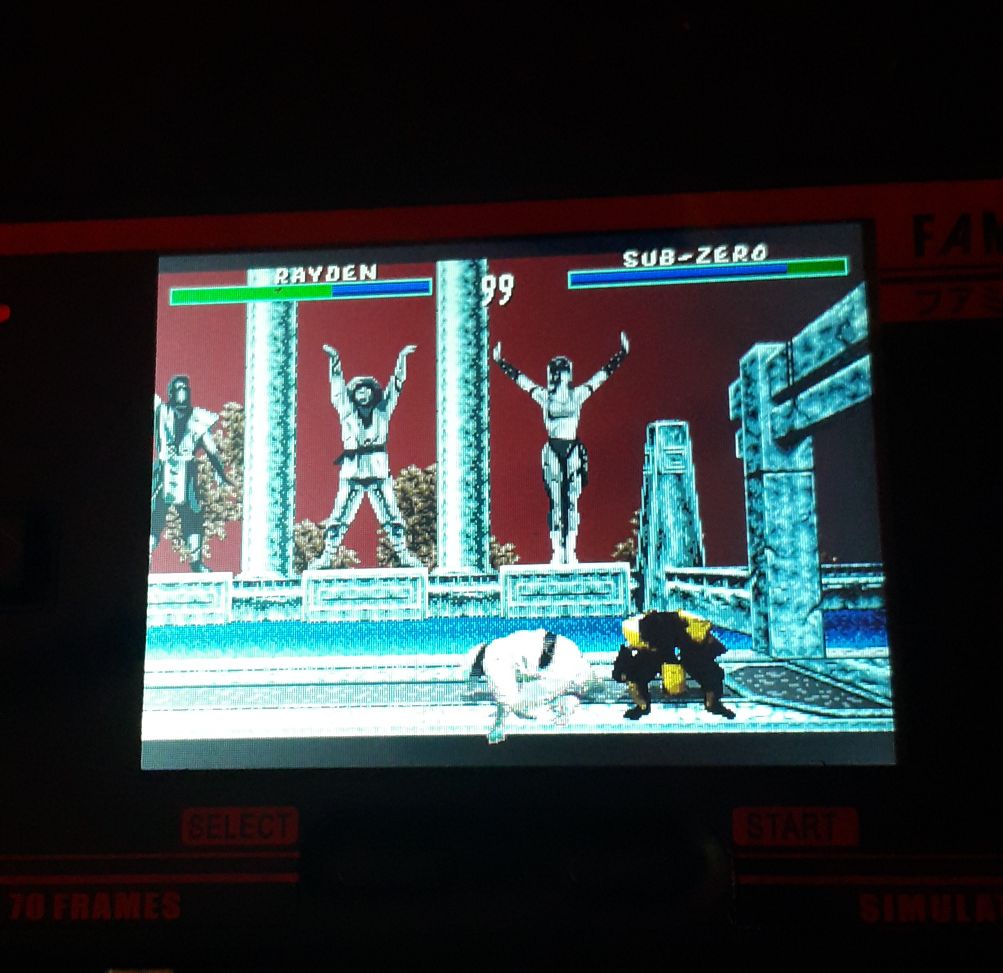
最近编辑记录 neotendo (2022-08-25 23:51:23)
离线
楼主 #964 2022-08-26 10:30:03 分享评论
Re: 研究FC3000掌機的開源可行性
@neotendo
Congratulations !
I am very happy to see Linux OS runs on your FC3000 ~
[Q1] sound not working
In general, there is an enable pin in amplifier IC to mute or unmute sound.
You can use multimeter to see where this pin connects to.
[Q2] most buttons not working
You can use multimeter to find all of them out.
Then you need update changes into kernel/drivers/input/keyboard/suniv-keypad.c file.
[Q3] green power led not working
As I known, the LED isn't controlled by F1C100S.
It is just a power indicator.
[Q4] is it possible to inject the new lcd code into an stock v1 or v2 rom?
Yes, it is possible but you need reverse and analyze stock firmware in assembly to see how to do inject.
If you can do this, we appreciate your efforts.
[Q5] colors wrong
You can change the settings (swap r-g-b) in LCD panel or framebuffer driver.
离线
#965 2022-08-26 16:42:25 分享评论
- neotendo
- 会员
- 注册时间: 2022-08-19
- 已发帖子: 180
- 积分: 203
Re: 研究FC3000掌機的開源可行性
@司徒
Got the colors fixed now👍
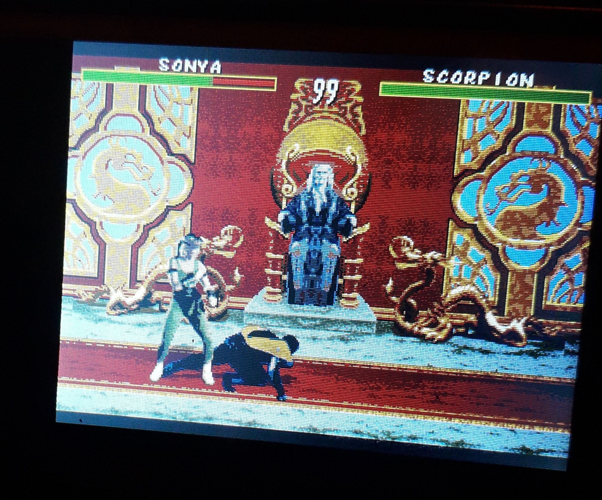
最近编辑记录 neotendo (2022-08-26 16:43:14)
离线
#966 2022-08-26 19:34:58 分享评论
- neotendo
- 会员
- 注册时间: 2022-08-19
- 已发帖子: 180
- 积分: 203
Re: 研究FC3000掌機的開源可行性
@司徒
(injecting lcd code into stock rom) - thats too much for me ![]()
(wrong colors) - Fixed
(Green LED) - Not important
(Sound) - Can you point me to the right file? I then have to find out the port/pin and then change it in the file, right?
(Buttons) - I then have to find out the port/pin and then change it in the file, right?
ps: how i can enter the gmenu2x app? i accidentally accessed it yesterday and fc3000 boots into gmenu2x everytime, now it's gone after flashing linux image of course.
pps: fc 3000 does not boot with my rootfs, filesize is only 25MB, it's missing the boot folder, but fc3000 does even not boot after manually adding boot folder.
kind regards
最近编辑记录 neotendo (2022-08-26 20:41:16)
离线
楼主 #967 2022-08-26 22:23:04 分享评论
Re: 研究FC3000掌機的開源可行性
@neotendo
[Q1] Sound
Source code: kernel/sound/soc/suniv/dac.c
In our FC3000, sound signal is connected to LM4890 amplifier IC directly and the SHUTDOWN pin is connected to 3.3V, which is always in unmute state.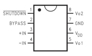
So, you need to check whether the hardware is same as ours or not.
If not, it may be controlled by mute/unmute pin.
Check your sound hardware first and then we can make decision for next step.
LM4890 location in our FC3000: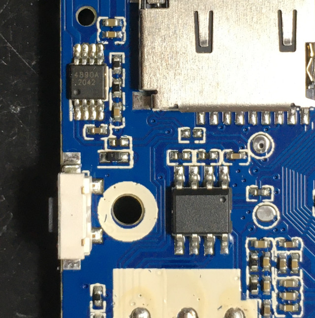
[Q2] Buttons
Source code: kernel/drivers/input/keyboard/suniv-keypad.c
Find all of GPIO pins and then I will teach you how to modify in kernel source code.
All of GPIO pins in our FC3000: https://steward-fu.github.io/website/handheld/fc3000/pin.htm
[Q3] how i can enter the gmenu2x app?
Please post the content of "/etc/main" file.
[Q4] fc3000 does not boot with my rootfs
If you need more detailed information about why your rootfs cannot be launched properly, you need solder UART to see detailed logs.
UART pin: https://steward-fu.github.io/website/handheld/fc3000/uart.htm
离线
#968 2022-08-27 00:02:27 分享评论
- neotendo
- 会员
- 注册时间: 2022-08-19
- 已发帖子: 180
- 积分: 203
Re: 研究FC3000掌機的開源可行性
@司徒
thank you very much, you are the best <3
离线
#969 2022-08-27 03:43:03 分享评论
- neotendo
- 会员
- 注册时间: 2022-08-19
- 已发帖子: 180
- 积分: 203
Re: 研究FC3000掌機的開源可行性
@司徒
hmmm, ok... i have no main in my selfmade rootfs (i think buildroot does not compile all what is needed, i believe there is no SDL, X11 or whatever either)
this is in the main file from your prebuild linux images
#!/bin/sh
export HOME=/mnt
export SDL_NOMOUSE=1
swapon /mnt/.swap.img > /dev/null 2>&1
/usr/bin/daemon&
while [ 1 ]
do
cd /mnt/gmenu2x
./gmenu2x > /dev/null 2>&1
done
And it boots into that menu
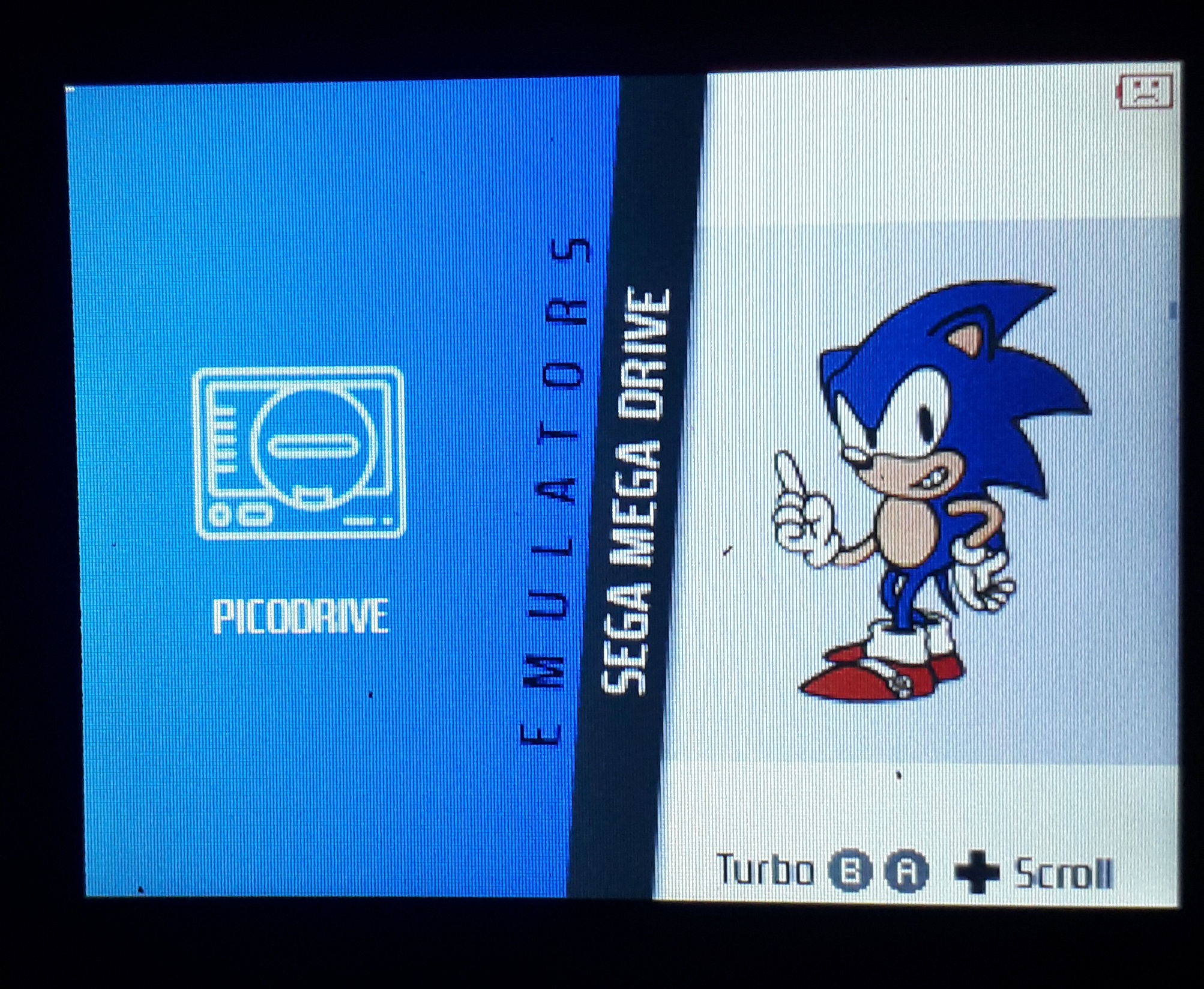
But i want to switch to the "filebrowser" menu
最近编辑记录 neotendo (2022-08-27 07:42:55)
离线
楼主 #970 2022-08-27 12:48:27 分享评论
Re: 研究FC3000掌機的開源可行性
@neotendo
What is filebrowser menu ?
Do you mean the ROMS list menu you can select the rom to be loaded in PICRODRIVE emulator ?
If yes, you need to press A button and then it shows ROMS lists for you.
Before this, you need make sure all of buttons can work properly.
I mean your input driver can work properly.
离线
#971 2022-08-27 18:56:46 分享评论
- neotendo
- 会员
- 注册时间: 2022-08-19
- 已发帖子: 180
- 积分: 203
Re: 研究FC3000掌機的開源可行性
@司徒
No idea how I got there, but the menu looked something like this (every time after booting)
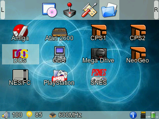
最近编辑记录 neotendo (2022-08-27 18:57:44)
离线
楼主 #972 2022-08-27 20:32:37 分享评论
Re: 研究FC3000掌機的開源可行性
@neotendo
GUI is very complicated than you think and there are many variants based on classical GMenu2X GUI.
And there are many configurations you need to know how to configure for your need (google is your friend).
It is a long story in open source handheld.
If you are interested about this, I can explain for you later.
In current stage, it will be good if all of drivers are ready.
离线
#973 2022-08-27 23:38:35 分享评论
- neotendo
- 会员
- 注册时间: 2022-08-19
- 已发帖子: 180
- 积分: 203
Re: 研究FC3000掌機的開源可行性
@司徒
As I said, I just pressed a few keys or something and after a restart it suddenly looked like this, no idea
离线
#974 2022-08-28 01:47:03 分享评论
- neotendo
- 会员
- 注册时间: 2022-08-19
- 已发帖子: 180
- 积分: 203
Re: 研究FC3000掌機的開源可行性
@Situ
I checked the sound chip (4890s), shutdown pin = 0-1.2v (low or floating), traced the pin to cpu (see pictures)
Hopefully my cpu is f1c100s pin compatible (i can not find the PAx pins)
最近编辑记录 neotendo (2022-08-28 05:19:01)
离线
楼主 #975 2022-08-28 08:53:22 分享评论
Re: 研究FC3000掌機的開源可行性
@neotendo
[Q1] GUI issue
I have no idea too.
[Q2] Sound issue
It is PA2 (TPY1) as the following image shown: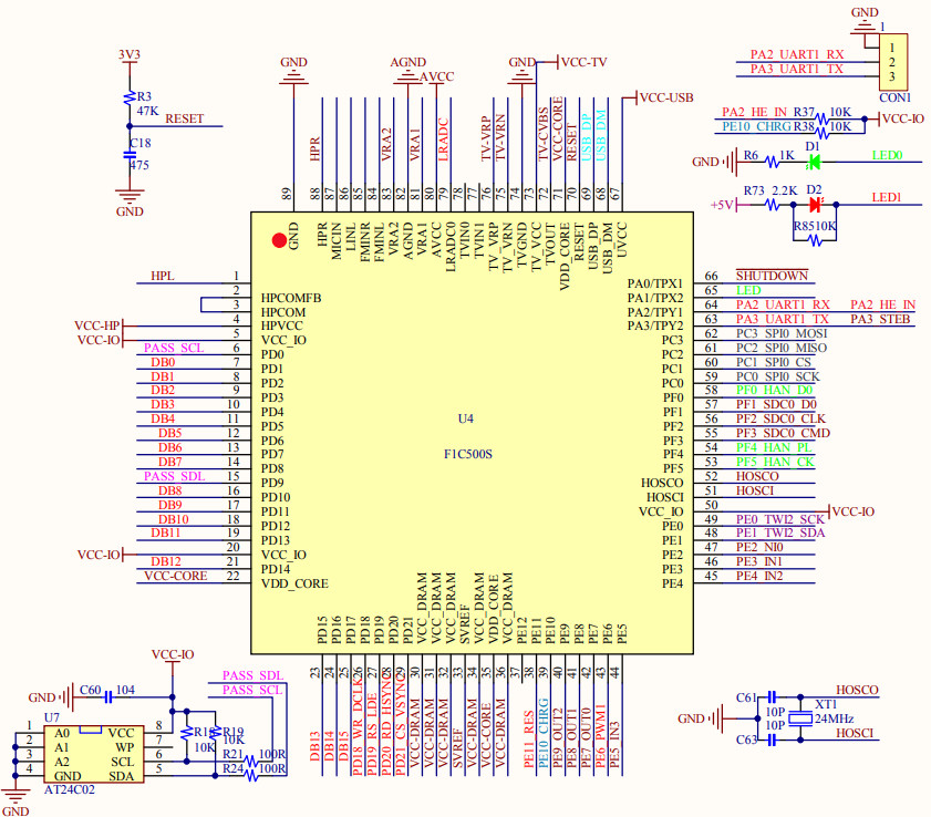
We need configure PA2 as OUTPUT so that it can be controlled as HIGH and the bits for PA2 are bit8 ~ bit10:
Source code: kernel/sound/soc/suniv/dac.c
suniv_variant = 1: PocketGo
suniv_variant = 2: TRIMUI
suniv_variant = 3: FC3000
Change L144 as the following one:
129 static void suniv_gpio_init(void)
130 {
131   uint32_t ret;
132
133   if(suniv_variant == 0){
134     ret = readl(iomm.gpio + PA_CFG0);
135 #if POCKETGO_USE_EARPHONE
136     ret&= 0xfffff0f0;
137 #else
138     ret&= 0xfffffff0;
139 #endif
140     ret|= 0x00000001;
141     writel(ret, iomm.gpio + PA_CFG0);
142     suniv_setbits(iomm.gpio + PA_DATA, (1 << 0));
143   }
144   else if((suniv_variant == 1) || (suniv_variant == 2)){
145     ret = readl(iomm.gpio + PA_CFG0);
146     ret&= 0xffffff0f;
147     ret|= 0x00000010;
148     writel(ret, iomm.gpio + PA_CFG0);
149     suniv_setbits(iomm.gpio + PA_DATA, (1 << 1));
150   }
151 }
离线
#976 2022-08-28 17:20:57 分享评论
- neotendo
- 会员
- 注册时间: 2022-08-19
- 已发帖子: 180
- 积分: 203
Re: 研究FC3000掌機的開源可行性
@Situ
I'm going crazy ![]() , the only thing that happens is that the green LED lights up hahaha
, the only thing that happens is that the green LED lights up hahaha
The Green LED is connected at Pin 65(PA1)
i slowy believe that my board has many different pinouts / connections then yours
maybe i cut the shutdown line and wire it to the green LED, so i can use the uart1 later for debugging if needed, because snd shutdown line is connected to UART1 RX (PA2 Pin 64)
最近编辑记录 neotendo (2022-08-28 17:56:03)
离线
#977 2022-08-28 18:03:20 分享评论
- neotendo
- 会员
- 注册时间: 2022-08-19
- 已发帖子: 180
- 积分: 203
Re: 研究FC3000掌機的開源可行性
@Situ
yes, my board has lot differences, my UART1 RX pad from your picture is GND on my board.
seems my CPU is a chinese knockoff or much different version
I can't thank you enough for helping me <3
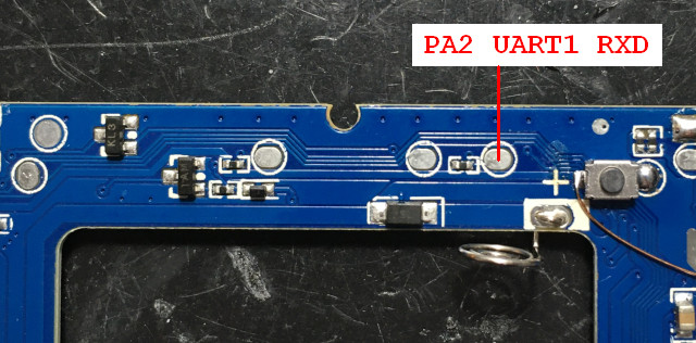
最近编辑记录 neotendo (2022-08-28 18:07:21)
离线
楼主 #978 2022-08-28 20:30:14 分享评论
#979 2022-08-28 21:21:41 分享评论
- neotendo
- 会员
- 注册时间: 2022-08-19
- 已发帖子: 180
- 积分: 203
Re: 研究FC3000掌機的開源可行性
@neotendo
ha ha, it seems very different compared with our FC3000.
It is more easy to resolve the sound issue if cut the SHUTDOWN line and then connect to 3.3v.
For debug purpose, you can also use UART0 for debug log.
Haha, ok, i bypassed the shutdown pin to 3v from the spi flash, sound is working now but there is a whining noise (from display or a coil)
I try to trace the buttons at the moment, i found out that L1 and R1 are connected to A and B, what a shame.
最近编辑记录 neotendo (2022-08-28 21:39:03)
离线
#980 2022-08-28 23:18:50 分享评论
- neotendo
- 会员
- 注册时间: 2022-08-19
- 已发帖子: 180
- 积分: 203
Re: 研究FC3000掌機的開源可行性
@Situ
Tracing my buttons done!
L1 = A
R1 = B
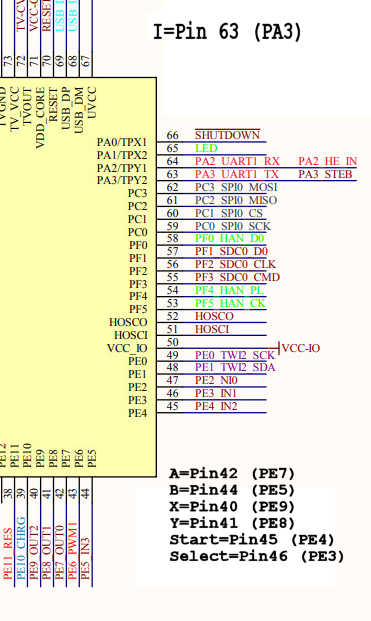
i tried this, but results are not as expected (UP/DOWN/LEFT/RIGHT are working)
suniv-keypad.c in function static int __init kbd_init(void)
else if(suniv_variant == 2) {
I_UP = ((32 * 5) + 0);
I_DOWN = ((32 * 5) + 5);
I_LEFT = ((32 * 5) + 4);
I_RIGHT = ((32 * 4) + 2);
I_A = ((32 * 4) + 7); //PE7
I_B = ((32 * 4) + 5); //PE5
I_X = ((32 * 4) + 9); //PE9
I_Y = ((32 * 4) + 8); //PE8
I_L1 = ((32 * 4) + 7); //PE7 (L1 = A)
I_R1 = ((32 * 4) + 5); //PE5 (R1 = B)
I_MENU = ((32 * 0) + 3); //PA3
I_L2 = ((32 * 4) + 10);
I_R2 = ((32 * 4) + 7);
...
最近编辑记录 neotendo (2022-08-29 00:19:55)
离线
楼主 #981 2022-08-29 13:03:23 分享评论
Re: 研究FC3000掌機的開源可行性
@neotendo
It seems (A / L1, B / R1) share the same I/O pins in your FC3000.
In our FC3000, the designing is almost same as yours but different buttons mapping.
The following schematic I depicted shows the buttons share same I/O pins in our FC3000: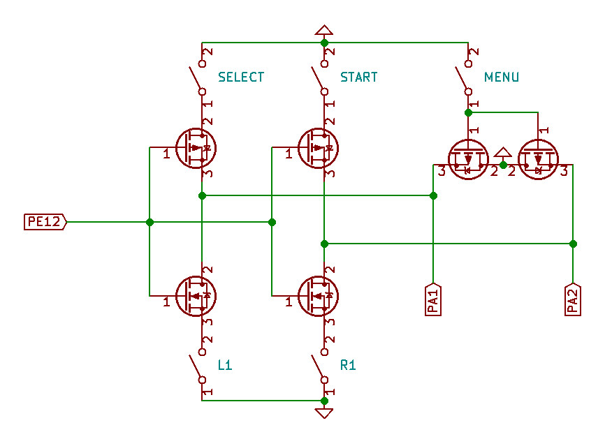
And functionality is shown in the following image: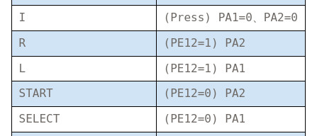
Here is the code shows how to check MENU button:
290       l = gpio_get_value(I_L1);
291       r = gpio_get_value(I_R1);
292       if((l == 0) && (r == 0)){
293         val|= R_MENU;
294       }
Check PE12 firstly to see whether it connects to NMOS or PMOS elments or not.
离线
#982 2022-08-29 18:30:14 分享评论
- neotendo
- 会员
- 注册时间: 2022-08-19
- 已发帖子: 180
- 积分: 203
Re: 研究FC3000掌機的開源可行性
@司徒
as far i can tell, I,L,R,START,SELECT are switching against GND (i hold one probe on GND, one probe on START for example, got connection when i press it (BEEP).
PS: looks like every button switches against GND, so no multiplexing
最近编辑记录 neotendo (2022-08-29 18:34:22)
离线
楼主 #983 2022-08-29 19:18:33 分享评论
#984 2022-08-29 19:28:08 分享评论
- neotendo
- 会员
- 注册时间: 2022-08-19
- 已发帖子: 180
- 积分: 203
Re: 研究FC3000掌機的開源可行性
@neotendo
May I know how did you debug this issue on your FC3000 ? Using multimeter only ?
yes, multimeter and my eyes with magnification glas ![]()
The line from start and select beeps when I check the negative pole of the battery
START -> PE4
SELECT -> PE3
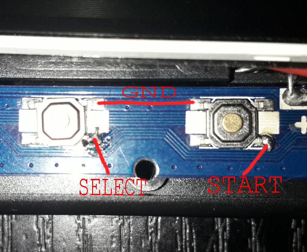
最近编辑记录 neotendo (2022-08-29 19:40:03)
离线
#985 2022-08-29 19:47:32 分享评论
- neotendo
- 会员
- 注册时间: 2022-08-19
- 已发帖子: 180
- 积分: 203
Re: 研究FC3000掌機的開源可行性
i changed some code for testing in...
static void fc3000_handler(unsigned long unused)
and
static int __init kbd_init(void)
now a have sega buttons A,B,C (FC3000 Buttons X,B,A) in Picodrive Emulator working
suniv-keypad.c_20220829-2012.txt
PS: FC 3000 buttons A and B working. when i press A or B in menu, they are corresponded with (B=Cancel, A Select).
funny, traced the lines, for example A goes to PE7 but has to write PE5 in the code
and here is a video about the "whining" sound
https://youtu.be/RFDxZAKQIuo
my FC3000 came from hell
最近编辑记录 neotendo (2022-08-29 20:25:44)
离线
楼主 #986 2022-08-29 20:50:50 分享评论
Re: 研究FC3000掌機的開源可行性
@neotendo
Good spot !
I need to check whether we are on the same page or not.
Is our goal to find out why L/R and A/B use the same pins ?
If yes, please provide PCB front view image without LCD panel.
(you have already provided PCB back view in previous testing)
I would like to check something on this PCB.
In such scenario, black box testing is more powerful than white box testing.
I have an idea for this issue based on kernel level testing.
I will explain to you later.
离线
#987 2022-08-29 20:57:15 分享评论
- neotendo
- 会员
- 注册时间: 2022-08-19
- 已发帖子: 180
- 积分: 203
Re: 研究FC3000掌機的開源可行性
@司徒
L1/R1 are electrical connected with A/B, i must cut the trace and connect it to any free pin on the mcu if possible.
atleast i want to get A,B,X,Y,START,SELECT,I working.
the whinig noise in the speaker comes from the LCD, when i press I the noise is little lower.
i will take photos from the pcb for you of course.
离线
#988 2022-08-29 21:17:34 分享评论
- neotendo
- 会员
- 注册时间: 2022-08-19
- 已发帖子: 180
- 积分: 203
Re: 研究FC3000掌機的開源可行性
here are the photos my friend
PS: Just found out, TV-OUT does not function either (not important)

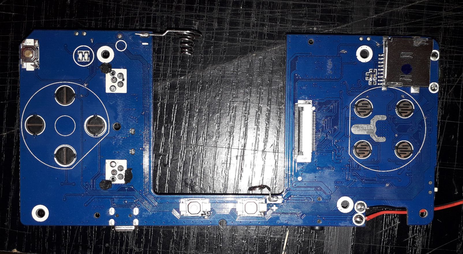
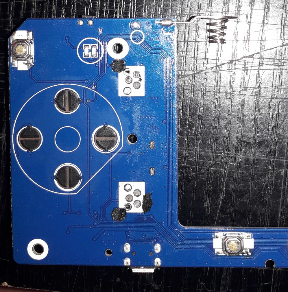
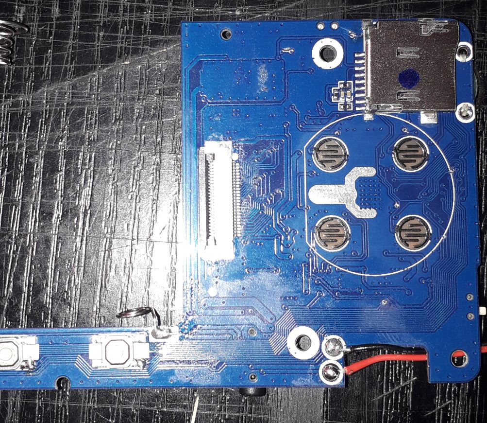
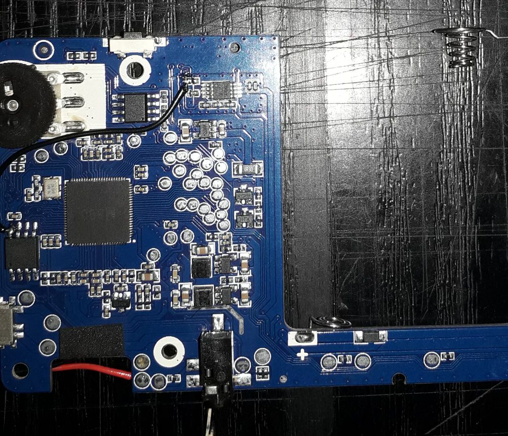
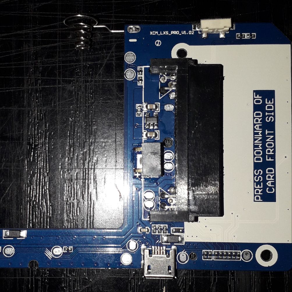
最近编辑记录 neotendo (2022-08-29 22:23:45)
离线
#989 2022-08-30 04:51:24 分享评论
- neotendo
- 会员
- 注册时间: 2022-08-19
- 已发帖子: 180
- 积分: 203
Re: 研究FC3000掌機的開源可行性
@Situ
All buttons but I(Menu) working now.
Since my I button connects to PA3 i think this pin is not in input mode!?
PS: when reading ((32 *4) + 6) system does not boot when Green LED is on via DAC.C (your attempt to enable sound but only did the Green LED Light up)
AND.... the coil noise is gone when setting backlight to 100%
PPS: Thats not me in the twitch stream
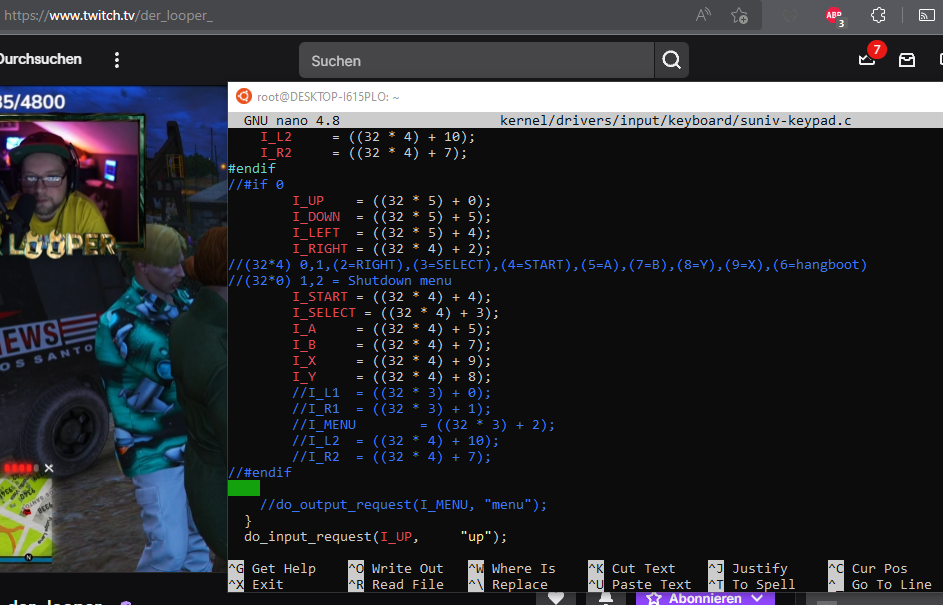
最近编辑记录 neotendo (2022-08-30 06:38:44)
离线
#990 2022-08-30 15:10:48 分享评论
- neotendo
- 会员
- 注册时间: 2022-08-19
- 已发帖子: 180
- 积分: 203
Re: 研究FC3000掌機的開源可行性
@Situ
I got all buttons working, only need to cut traces from L1,R1 and connect it to free io pins on mcu if possible.
do_input_request(I_MENU,"menu") and gpio_get_value(I_MENU) like all other Inputs.
L1 and R1 are simulated (L1 = Y+LEFT, R1 = Y+RIGHT) to change sections in gmenu2x atleast.
MY 5 CENTS: i guess the encryption/decryption chip is only for the roms when inserting the "cartridge". these roms (ziped files found in folder pro/rom) ends with .ky and looks enrypted in hexeditor.
suniv-keypad.c_20220830-1548.txt
最近编辑记录 neotendo (2022-08-30 17:57:09)
离线
楼主 #991 2022-08-30 19:12:04 分享评论
Re: 研究FC3000掌機的開源可行性
@neotendo
[Q1] TV-OUT
It is not implemented yet and no any plan for this feature.
[Q2] Since my I button connects to PA3 i think this pin is not in input mode!?
PA3 was mapped as Y button.
[Q3] when reading ((32 *4) + 6) system does not boot when Green LED is on via DAC.C
PE6 was used as PWM output for LCD backlight.
[Q4] the coil noise is gone when setting backlight to 100%
Yes, sound signal is effected by PWM.
Ref:
https://whycan.com/t_6647.html#p78183
https://whycan.com/t_6647.html#p76849
[Q5] I got all buttons working, only need to cut traces from L1,R1 and connect it to free io pins on mcu if possible.
Goooood !
[Q6] i guess the encryption/decryption chip is only for the roms when inserting the "cartridge".
We only focusd on Linux OS so far.
If you have any update information, it is welcome to share with us.
I think you have already completed all of tasks for Linux OS on your FC3000.
It is excellent task done by yourself.
If it is possible, please help share the image file that can be flashed into MicroSD to someone who needs it.
Thanks ![]()
离线
楼主 #992 2022-08-30 19:31:17 分享评论
Re: 研究FC3000掌機的開源可行性
By the way, here is the way (black box testing) to find L1 and R1 in kernel level.
(it assumes that they are not physically connected with A and B buttons):
1. List out all of unused GPIO, ex: PAx, PBx, PCx and so on.
2. Change framebuffer as console mode that log can be printed on LCD.
3. Try each unused GPIO and configure it as output (only 1 ouput for every round).
4. Press L1 and R1 and check the result on LCD.
But I am wrong because L1=A and R1=B, ha ha
离线
#993 2022-08-30 19:53:14 分享评论
- neotendo
- 会员
- 注册时间: 2022-08-19
- 已发帖子: 180
- 积分: 203
Re: 研究FC3000掌機的開源可行性
@司徒
[A1] no problem, not important
[A2] "I" now working without modification "I_MENU = ((32 * 0) + 3);"
[A3] ahhh, that's logical then
[A4] till now i do not knew how to set the brightness, now after configure the system to 100% brightness, all went fine
[A5] Danke<3
[A6] just came in my head, only an idea
I thank you so much for your help, my FC3000 would be complete dump without you. i am happy to work with you, was a lot of fun.
i wil try to optimice the modified code, maybe add a new variant (fc3000_old).
i will even try to enable the snd_shutdown pin via gpio, so everyone who needs this firmware can use it without hardware modification.
can you tell me how i can add a new variant?
i saw in an other forum that someone got the .wst files decrypted, do you have the tool or can you maybe ask the user for his tool please (User: aoa)?
https://boards.dingoonity.org/other-game-systems/fc3000-linux-porting-from-scratch/100/
最近编辑记录 neotendo (2022-08-30 20:07:16)
离线
#994 2022-08-30 20:01:34 分享评论
- neotendo
- 会员
- 注册时间: 2022-08-19
- 已发帖子: 180
- 积分: 203
Re: 研究FC3000掌機的開源可行性
@Situ
Thank's for the L1/R1 information, i will try it.
i will try to edit the u-boot code to add an fc3000_old variant, so everyone can compile kernel/uboot atleast.
i still have an rootfs problem. rootfs is too small and does not boot, but as long i can boot your linux with my u-boot, i am happy with that.
离线
楼主 #995 2022-08-30 22:18:31 分享评论
Re: 研究FC3000掌機的開源可行性
@neotendo
[Q1] can you tell me how i can add a new variant?
In kernel folder, run the following command and then you will know how to do next
$ grep suniv_variant . -r[Q2] do you have the tool or can you maybe ask the user for his tool please (User: aoa)?
I don't have any tool to decrypt ".wst" file.
I have asked "aoa" for further information on dingoonity forum.
[Q3] rootfs is too small and does not boot
Make sure SDL v1.2 library is included and then edit "/etc/inittab" and "/etc/main" files.
离线
#996 2022-08-30 22:34:41 分享评论
- neotendo
- 会员
- 注册时间: 2022-08-19
- 已发帖子: 180
- 积分: 203
Re: 研究FC3000掌機的開源可行性
@司徒
thank you, i will add variant 3 for fc3000_old
离线
#997 2022-08-31 05:59:50 分享评论
- neotendo
- 会员
- 注册时间: 2022-08-19
- 已发帖子: 180
- 积分: 203
Re: 研究FC3000掌機的開源可行性
@Situ
All right, sound is working with unmodded connection.
Now the firmware is able to run on unmodified fc3000 old version.
I need to flash your linux firmware without roms, and dump it with my uboot.
Can you tell me how to dump only the needed data like your linux images (~2GB)?
dd ..... bs=2048M count=1 ?
I do not want to dump a 32GB sdcard.
The kernel source code needs still some cleanup, but i was abe to compile it with
./run.sh fc3000_old
PS: only thing left, maybe fixing the battery level icon (shows dead/empty battery all the time)
最近编辑记录 neotendo (2022-08-31 06:06:54)
离线
楼主 #998 2022-08-31 08:59:41 分享评论
Re: 研究FC3000掌機的開源可行性
@neotendo
[Q1] sound is working with unmodded connection.
Do you mean the noise issue is fixed without any hardware modding ?
[Q2] Can you tell me how to dump only the needed data like your linux images (~2GB)?
Here are the steps to create 2GB image and then you can flash what you want into this 2GB image file
$ sudo dd if=/dev/zero of=test.img bs=1M count=2024
	2024+0 records in
	2024+0 records out
	2122317824 bytes (2.1 GB, 2.0 GiB) copied, 1.83519 s, 1.2 GB/s

$ sudo fdisk test.img
	Command (m for help): n
	Partition type
	   p   primary (0 primary, 0 extended, 4 free)
	   e   extended (container for logical partitions)
	Select (default p): p
	Partition number (1-4, default 1):
	First sector (2048-4145151, default 2048): 16384
	Last sector, +/-sectors or +/-size{K,M,G,T,P} (16384-4145151, default 4145151):

	Created a new partition 1 of type 'Linux' and of size 2 GiB.

	Command (m for help): p
	Disk test.img: 2 GiB, 2122317824 bytes, 4145152 sectors
	Units: sectors of 1 * 512 = 512 bytes
	Sector size (logical/physical): 512 bytes / 512 bytes
	I/O size (minimum/optimal): 512 bytes / 512 bytes
	Disklabel type: dos
	Disk identifier: 0x0eb9d800

	Device     Boot Start     End Sectors Size Id Type
	test.img1       16384 4145151 4128768   2G 83 Linux

	Command (m for help): w
	The partition table has been altered.
	Syncing disks.

$ sudo losetup -f test.img
$ sudo kpartx -a -v test.img
	add map loop0p1 (254:0): 0 4128768 linear 7:0 16384

$ sudo mkfs.vfat -F32 /dev/mapper/loop0p1
	mkfs.fat 4.1 (2017-01-24)

$ sudo fatlabel /dev/mapper/loop0p1 FC3000

$ sudo kpartx -d -v /dev/loop0
	del devmap : loop0p1

$ sudo losetup -d /dev/loop0
离线
#999 2022-08-31 14:15:28 分享评论
- neotendo
- 会员
- 注册时间: 2022-08-19
- 已发帖子: 180
- 积分: 203
Re: 研究FC3000掌機的開源可行性
@司徒
Noise is gone when setting backlight to 100.
Unmodded= you provided me the code for "dac.c" to poweron the amp chip, but only what happend was that the green led lights up.
So i bypassed the shutdown pin from the sound amplifier to 3.3v, cause uboot did not poweron the amplifier.
I got it working in "dac.c", green led on, and amp on.
So, everyone can use our linux version without modify the hardware.
I want to dump my OS like your linux images...
Partition 1 - 32MB empty (uboot)
Partition 2 - 256MB fat32 FC3000 (rootfs,mininit)
Partition 3 - ~2GB fat32 OD (folders,configs,menu etc)
All in one .img file.
The user has to expand Partition 3 after flashing on sdcard to the rest space
最近编辑记录 neotendo (2022-08-31 14:17:44)
离线
#1000 2022-08-31 16:42:38 分享评论
- neotendo
- 会员
- 注册时间: 2022-08-19
- 已发帖子: 180
- 积分: 203
Re: 研究FC3000掌機的開源可行性
!!! Celebrating Post #1000!!!
I proudly present.... Linux for the (originally incompatible) TFT FC3000 (old version)
A notice:
L1/R1 are hard coded to A/B so I added an L1/R1 simulation.
Hold X and tap DPAD Left for L1.
Hold X and tap DPAD Right for R1.
This allows you to switch sections in the menu.
Hopefully someone can use this firmware, thanks Situ for your hard work and help to port your linux to my FC3000 (old version).
Download link for "fc3000_old_tft_od_no_roms.7z"
https://mega.nz/file/jbxiWRZa#JmnwkdG57oYORvfYo9LbUwHZ1CRjU52H_5ppMoCuh80
FC3000 in Action
https://youtu.be/h37twdx07OQ
最近编辑记录 neotendo (2022-08-31 20:11:07)
离线
楼主 #1001 2022-08-31 16:56:24 分享评论
#1002 2022-08-31 19:23:49 分享评论
- neotendo
- 会员
- 注册时间: 2022-08-19
- 已发帖子: 180
- 积分: 203
Re: 研究FC3000掌機的開源可行性
快要可以看到第6頁了~哈~
hahaha 😊
PS: it is done! happy downloading
最近编辑记录 neotendo (2022-08-31 19:50:24)
离线
楼主 #1003 2022-08-31 20:00:53 分享评论
#1004 2022-08-31 20:14:14 分享评论
- neotendo
- 会员
- 注册时间: 2022-08-19
- 已发帖子: 180
- 积分: 203
Re: 研究FC3000掌機的開源可行性
@neotendo
Thanks for your efforts.
I will put this file on my github.
Thanks
you're welcome, was lot of fun, and maybe we can help 1 or 2 people with this port.
PS: Added an "FC3000 in Action" video to post #1000.
最近编辑记录 neotendo (2022-08-31 20:15:23)
离线
#1005 2022-09-01 04:40:43 分享评论
- neotendo
- 会员
- 注册时间: 2022-08-19
- 已发帖子: 180
- 积分: 203
Re: 研究FC3000掌機的開源可行性
I know somebody already mentioned that the I(Menu) key us not working in FBA, is there a solution or source code?
最近编辑记录 neotendo (2022-09-01 04:41:56)
离线
太原小智科技有限责任公司 - 东莞哇酷科技有限公司联合开发
