- 首页
- » 搜索
- » XIVN1987 发表的帖子
#4 Re: Cortex M0/M3/M4/M7 » DAPLink添加WINUSB支持。。 » 2025-09-23 00:02:30
@吴助建
刚刚试了一下 WinUSB 版本,,无需设置,,直接可以识别,,我用的 Ubuntu 24,不知道是不是跟系统版本有关。。
wmx@VM-Ubuntu:~$ sudo lsusb
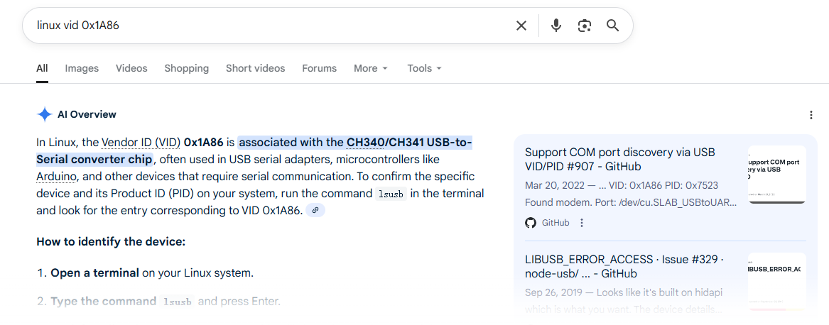
Bus 003 Device 005: ID 1a86:7021 QinHeng Electronics XV-Link CMSIS-DAP
... ...

wmx@VM-Ubuntu:~$ sudo ~/vexe/bin/pyocd list
  #   Probe/Board                  Unique ID      Target
----------------------------------------------------------
0 XIVN1987 XV-Link CMSIS-DAP C6D28F062F96 n/a #7 RISC-V » 调试器连接 APT32F1031,CKLink 成功,JLink 失败,,难道不同调试器实现的 cJTAG 有差异? » 2025-05-20 23:02:29
- XIVN1987
- 回复: 5
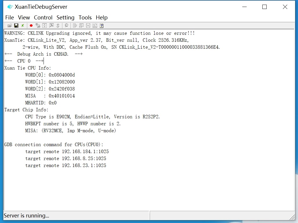
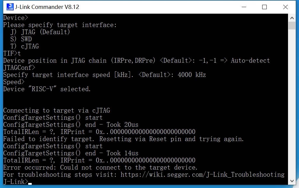
用的 JLink 版本是 J-Link OB-RA4M2,据说支持 ARM、RISC-V 内核,支持 SWD、JTAG、cJTAG 接口,,功能很全,,超过 J-Link v9,堪比 J-Link v12,只是速度低一些。。
用它连接 RISC-V 内核、JTAG 接口的 GD32VF103 成功。。连接 RISC-V 内核、cJTAG 接口的 APT32F1031 失败。。
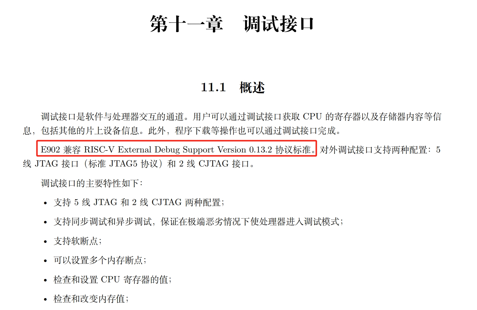
想到最可能的原因是 J-Link 和 APT32F1031 实现的 cJTAG 接口协议有差异,,这个芯片用的 CPU 是平头哥的玄铁 E902,不知道平头哥的 cJTAG 实现是否和 J-Link 的 cJTAG 实现兼容。。
#10 Cortex M0/M3/M4/M7 » VSCode + Cortex-Debug + pyocd 调试程序无法停在 main 函数的解决方法 » 2025-05-05 21:04:44
- XIVN1987
- 回复: 0
使用 VSCode + Cortex-Debug + pyocd 调试 SWM34S micropython 程序,,由于 pyocd 中没有 SWM34S,所以在配置文件(https://github.com/Synwit-Co-Ltd/micropython/blob/master/upy34s.code-workspace)中通过 "device": "Cortex-M33" 选择器件为 M33,,结果进入调试时程序无法停在 main 函数。。
多方测试发现将 launch config 中的 "device": "Cortex-M33" 替换为 "targetId": "m487jidae",,即将器件选择为 pyocd 中有的一个具体器件(而非器件内核),,则问题解决。。
经测试发现,具体的原因是默认的 target cortex_m 的 MemoryMap 定义中没有 FlashRegion,,已将此问题反馈给 pyocd:https://github.com/pyocd/pyOCD/issues/1756
#11 Cortex M0/M3/M4/M7 » DAPLink 信号线要串电阻,,否则容易通信失败。。 » 2025-05-05 20:37:10
- XIVN1987
- 回复: 8
做了个 DAPLink:https://oshwhub.com/xivn1987/DAPLink-HS
烧录 STM32F411 一直失败,,报错没有ACK,,但是只要像下面那样在 SWCLK 引脚上连一根线(线的另一端悬空)烧录就能成功
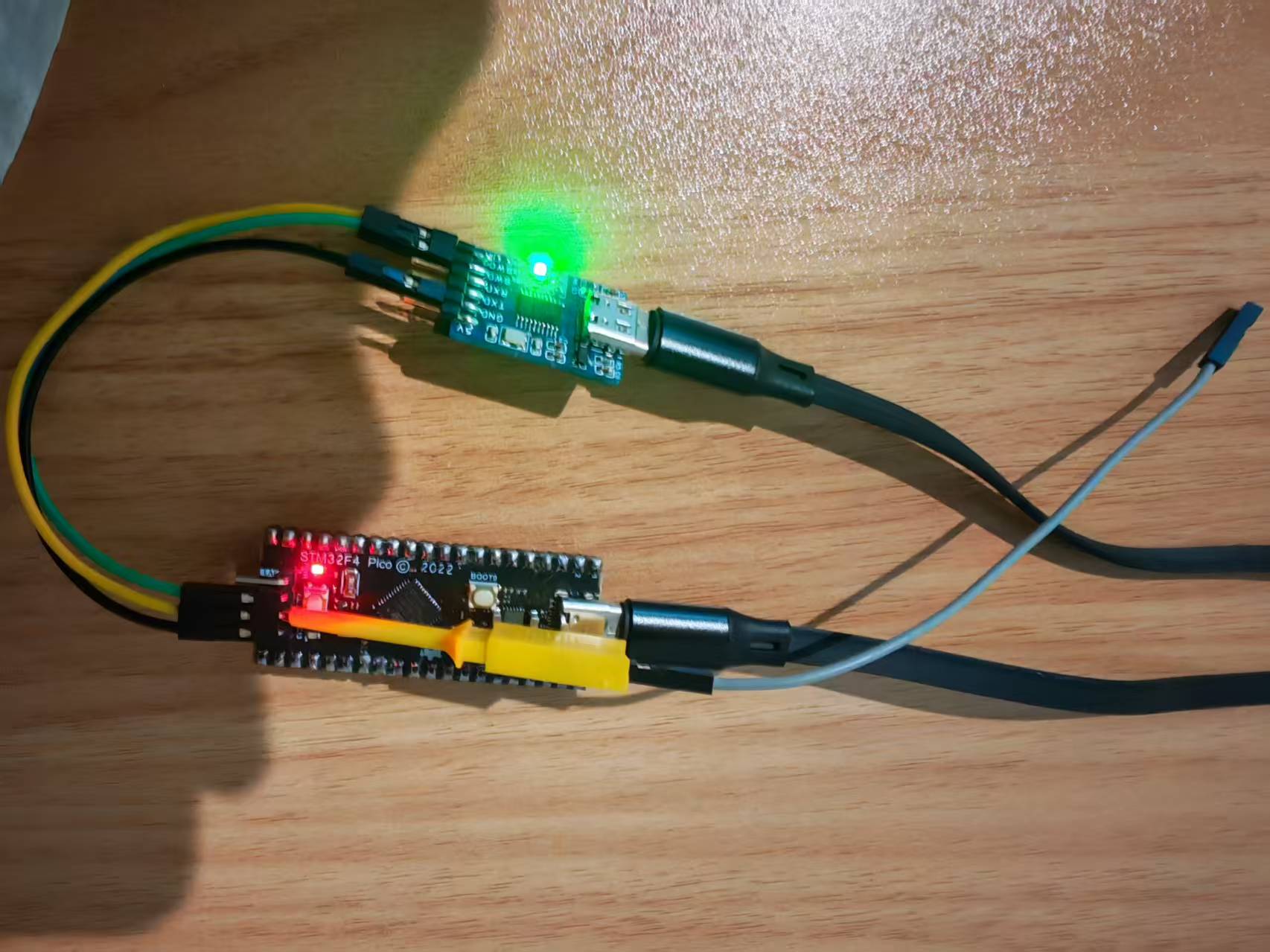
搞不明白是为什么,,于是在某QQ群里求助,,有大侠指点说在 SWCLK 线上串电阻,,试了下串 100 或 200 欧姆电阻后果然就不再出错了。。
当初画板子光想着简洁、省事儿了,,给自己挖了个大坑 ![]()
#12 Re: 全志 SOC » 全志2xA76核心的终于出来了,为啥不直接4XA76 » 2025-05-03 14:46:29
#14 Re: PikaPython(嵌入式Python引擎) » 在PC上用哪个函数可以把加载的代码转成字节码? » 2025-02-13 09:54:03
https://whycan.com/t_7470.html
【3. 现在这个Python脚本编译后是需要编译进固件吗?是否可以单独写到FLASH或者内存中,用vm来动态调用,是否支持直接更新解析后的字节码?】
Python脚本可以直接编译进固件中,也可以写入到FLASH中,PikaScript读取字符串形式的Python脚本即可运行。Pika将Python脚本解析为字节码的过程可以在MCU上完成,也可以在PC上完成,解析后的字节码同样以字符串形式,即可交给VM执行。
在PC上解析字节码可以使用pikascript/tools/pikaByteCodeGen工具。
#15 Re: Cortex M0/M3/M4/M7 » DAPLink添加软件复位功能。。 » 2024-12-12 11:39:32
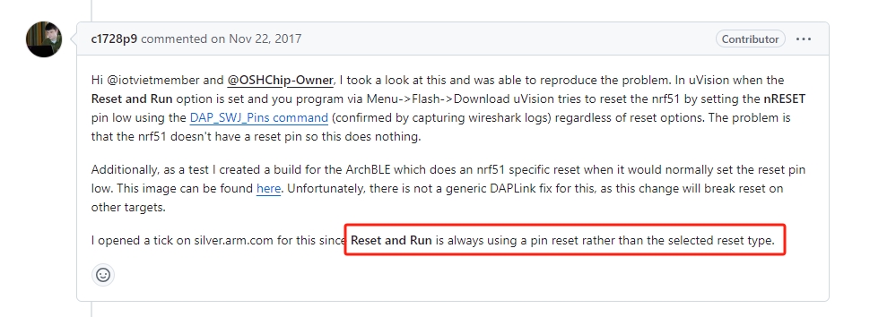
https://github.com/ARMmbed/DAPLink/issues/166
看起来 Keil 似乎有 bug,,不管你选择的复位方式是 HW RESET 硬件复位还是 SYSRESETREQ 软件复位,,它在执行 Reset and Run 时总是使用硬件复位
#16 Re: Cortex M0/M3/M4/M7 » DAPLink添加软件复位功能。。 » 2024-12-10 23:30:54
#17 Re: 全志 SOC » 有哪些RTOS系统支持Camera框架的? » 2024-11-26 12:45:14
#18 Re: RK3288/RK3399/RK1108 » 为什么瑞芯微公开资料这么少呢 » 2024-11-21 11:29:03
#19 Re: 工业芯 匠芯创 » D213ECV 使用 Aiburn 无法烧录 » 2024-10-23 16:02:58
#20 Re: 工业芯 匠芯创 » Jlink能连D133么 » 2024-10-17 08:54:25
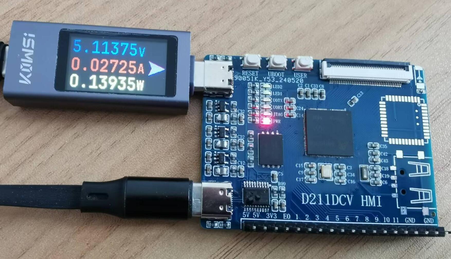
#27 工业芯 匠芯创 » D211DCV 画了块板子,,AiBurn 烧录失败,,请求各位大牛指点。。 » 2024-05-26 11:21:31
- XIVN1987
- 回复: 12
之前画过一版,无法烧录:https://whycan.com/t_10422.html
当时怀疑可能的两个问题:
1、SPINAND 没有画等长
2、电源用的 LDO,发烫比较严重
这次改版解决了上述两个问题,,SPINAND 画了等长线,,电源换用了 SY8088AAC,,另外担心自己焊接功夫不过关,,特意用了 SMT 焊接。。可是回来测试发现还是无法烧录 ![]()
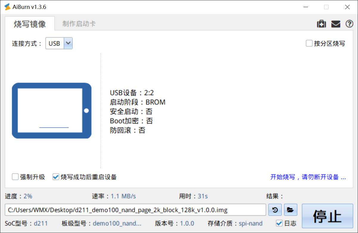
串口打印信息:
Pre-Boot Program ... (2023-11-09 20:38:24 248b01c)
DDR3 128MB
Going to init DDR3. freq: 672MHz
DDR3 initialized
PBP return

Pre-Boot Program ... (2023-11-09 20:38:24 248b01c)
DDR already initialized
13133259 13133636 13145886
PBP done

U-Boot SPL 2021.10 (Dec 06 2023 - 22:40:16 +0800)
[SPL]: Boot device = 7(BD_USB)
Trying to boot from RAM
Run U-Boot: upgrading mode
AiBurn 输出 log:
[debug] WinEvent: Some devnode changed
[debug] No device available

[debug] WinEvent: Some devnode changed
[debug] No device available

[debug] WinEvent: Some devnode changed
[debug] There are "1" device available

[debug] Try to connect the ArtInChip device "2:2" ...
[debug] Try to get Usb device hd info...
[debug] Get Usb device hd info success
[debug] The status of ArtInChip device: true
[debug] Start burn online ...
[debug] Progress range: 0 ~ 49743872

[debug] Burn Image file "C:/Users/WMX/Desktop/d211_demo100_nand_page_2k_block_128k_v1.0.0.img" ...

[debug] Meta 0 image.updater.ddr , size 27408 ...
[debug] Blocksize 4 , chunk 1048576 * 0 , rest 27408
[debug] Offset: 8704 Size: 27408
[debug] Dev "2:2" Send the rest data 27408
[debug] Don't check the result of image.updater.ddr

[debug] Meta 1 image.updater.env , size 16384 ...
[debug] Blocksize 4 , chunk 1048576 * 0 , rest 16384
[debug] Offset: 37376 Size: 16384
[debug] Dev "2:2" Send the rest data 16384

[debug] Meta 2 image.updater.uboot , size 826603 ...
[debug] Blocksize 4 , chunk 1048576 * 0 , rest 826603
[debug] Offset: 53760 Size: 826603
[debug] Dev "2:2" Send the rest data 826603

[debug] Meta 3 image.updater.logo , size 141709 ...
[debug] Blocksize 4 , chunk 1048576 * 0 , rest 141709
[debug] Offset: 881152 Size: 141709
[debug] Dev "2:2" Send the rest data 141709

[debug] Meta 4 image.updater.spl , size 128528 ...
[debug] Blocksize 4 , chunk 1048576 * 0 , rest 128528
[debug] Offset: 1024512 Size: 128528
[debug] Dev "2:2" Send the rest data 128528
[error] aicupg_trans_recv_pkt()208: CSW size 0, Operation timed out(-7)
[error] aicupg_cmd_send_fwc_data_final()777: Recv resp failed, expect 16, got 0
[debug] Don't check the result of image.updater.spl

[debug] Meta 5 image.info , size 2048 ...
[error] aicupg_trans_send_pkt()91: Send tag 0xc6b, size 0/16, Operation timed out(-7)
[error] aicupg_cmd_get_hwinfo()106: Send command failed. ret = 0, siz = 16
[debug] Wait to reconnect dev "2:2"
[debug] QTime("11:00:23.102") Wait for Dev "2:2" ready
[error] aicupg_trans_send_pkt()80: CBW tag 0xc6c, size 0, Operation timed out(-7)
[error] aicupg_cmd_get_hwinfo()106: Send command failed. ret = 0, siz = 16
[error] QTime("11:00:33.225") Dev "2:2" lost!
[error] Dev "2:2" is completely lost!
[debug] Update "fail_cnt" of "2024-05-26"
LCEDA 专业版工程文件:D211DCV.rar
请求各位大神帮忙看下,,可能是什么原因导致的,,谢谢了。。
#30 Re: 工业芯 匠芯创 » 有没有好用迷你的程序和gui工具推荐? » 2024-04-23 08:55:55
#31 Re: RISC-V » RISC-V 如何实现 __disable_irq()? » 2024-04-16 12:38:56
#32 Re: RISC-V » RISC-V 如何实现 __disable_irq()? » 2024-04-16 08:56:23
#33 Re: RISC-V » RISC-V 如何实现 __disable_irq()? » 2024-04-15 19:03:58
#34 RISC-V » RISC-V CLINT 中断处理与中断嵌套 » 2024-04-15 09:43:37
- XIVN1987
- 回复: 0
volatile int timer_n = 0;


void timer_handler (void) {
    timer_n++;
}

timer_handler:
    lui     a0, %hi(timer_n)
    lw      a1, %lo(timer_n)(a0)
    addi    a1, a1, 1
    sw      a1, %lo(timer_n)(a0)
    ret


__attribute__((interrupt))
void timer_handler (void) {
    timer_n++;
}

timer_handler:
    addi    sp, sp, -16
    sw      a0, 12(sp)                      # 4-byte Folded Spill
    sw      a1, 8(sp)                       # 4-byte Folded Spill
    lui     a0, %hi(timer_n)
    lw      a1, %lo(timer_n)(a0)
    addi    a1, a1, 1
    sw      a1, %lo(timer_n)(a0)
    lw      a0, 12(sp)                      # 4-byte Folded Reload
    lw      a1, 8(sp)                       # 4-byte Folded Reload
    addi    sp, sp, 16
    mret
对比发现,添加 __attribute__((interrupt)) 修饰后,编译器给用到的寄存器添加保存、恢复代码,并将 ret 替换为 mret.
既然 ISR 对自己使用的寄存器都会提前保存、返回时恢复,,那么发生中断嵌套就不会破坏 ISR 的上下文环境,,可以允许中断嵌套的发生
但是在中断返回时 CPU 需要 mepc 和 mstatus 中的信息确定返回地址和返回特权级,,这些寄存器编译器没有给我们保存、恢复,,因此还需要手动添加代码处理
__attribute__((interrupt))
void timer_handler (void) {
    int mepc, mstatus;

    asm("csrr %0, mepc\n\t"
        "csrr %1, mstatus\n\t"
        "csrsi mstatus, 8"      // mstatus.MIE = 1, interrupt enable
        : "=r" (mepc), "=r" (mstatus));

    // ISR code

    asm("csrci mstatus, 8\n\t"  // mstatus.MIE = 0, interrupt disable
        "csrw mepc, %0\n\t"
        "csrw mstatus, %1"
        : : "r" (mepc), "r" (mstatus));
}
实现中断嵌套的关键是在重新使能中断之前保存 mepc、mstatus,并在执行 mret 之前恢复它们
但在 CLINT 下实现中断嵌套没有意义,因为 CLINT 下没有中断优先级,中断嵌套只有配合可配置的中断优先级才有意义。所以一般 MCU 厂商会使用更高级的中断控制器替代 CLINT,而不会直接使用官方简陋的 CLINT,,比如沁恒 MCU 使用了自己设计的 PFIC 中断控制器,,添加了中断优先级等功能。。
#35 RISC-V » RISC-V 如何实现 __disable_irq()? » 2024-04-12 13:51:39
- XIVN1987
- 回复: 6
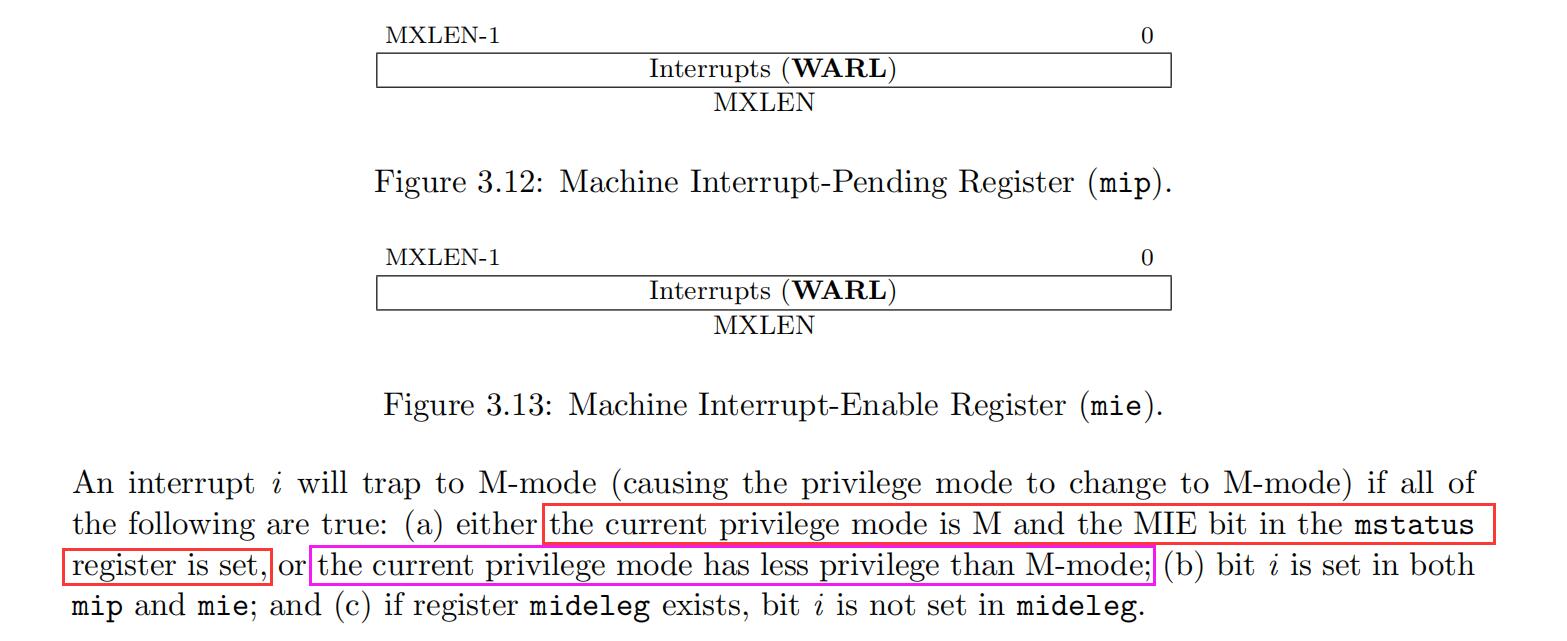
之前一直以为 mstatus.MIE 可以用作中断的全局总开关,,仔细看了 spec 才发现并不能
根据下面这说法,,如果程序正在用户模式执行,,然后来了中断,,即使 mstatus.MIE == 0,也会切换到机器模式去执行中断处理函数。。
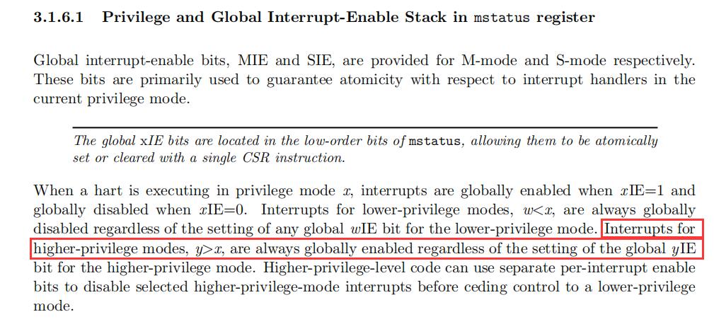
所以 RISC-V spec 里面并没有一个全局关闭中断的方法,,
查看沁恒驱动库中的 __disable_irq() 实现可以看到,,它是通过地址为 0x800 的 CSR 寄存器实现的,,而这个地址属于“User-Level Custom read/write”区,,也就是说,这是一个芯片厂商自定义的寄存器
RV_STATIC_INLINE void __disable_irq()
{
  __asm volatile ("csrw 0x800, %0" : : "r" (0x6000) );
}#36 Re: Cortex M0/M3/M4/M7 » 求教如何让MCU上电时立即halt » 2024-03-30 09:58:29
#39 Re: 工业芯 匠芯创 » D211DCV+W25N01GVZEIG 烧录固件不成功问题求助 » 2024-03-23 15:29:02
https://whycan.com/t_10422.html
我之前画了一块也是无法烧录,,怀疑是不是因为 SDNAND 连线没画等长,,看你这个画了等长还是烧录失败,,不好搞。。
#44 Re: Php/Nodejs/Web/HTML5/Javascript/微信开发/Python » 如何使用 Pyserial 访问 OrangePi 3B 的串口 » 2024-03-17 17:14:31
搜了下,,发现这个问题四年前就有人提了,,可惜还没解决。。有人提了 pr,,但作者还未 merge
#45 Php/Nodejs/Web/HTML5/Javascript/微信开发/Python » 如何使用 Pyserial 访问 OrangePi 3B 的串口 » 2024-03-17 12:03:19
- XIVN1987
- 回复: 3
使用 orangepi-config 使能 UART2 后,,在 /dev 下可以看到 ttyS2,,但如下代码查询结果为空:
In [10]: from serial.tools.list_ports import comports

In [11]: comports()
Out[11]: []
查看 comports 实现如下: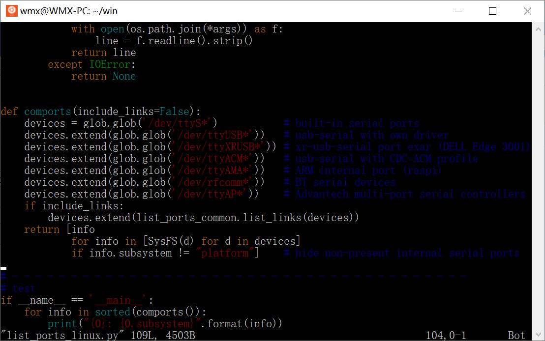
逐句执行 comports 语句:
In [16]: glob('/dev/ttyS*')
Out[16]: ['/dev/ttyS9', '/dev/ttyS7', '/dev/ttyS2', '/dev/ttyS1']

In [17]: [SysFS(d) for d in _]
Out[17]:
[<serial.tools.list_ports_linux.SysFS at 0x7f88996830>,
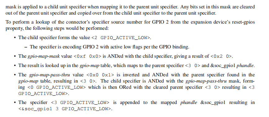
 <serial.tools.list_ports_linux.SysFS at 0x7f88997550>,
 <serial.tools.list_ports_linux.SysFS at 0x7f889979d0>,
 <serial.tools.list_ports_linux.SysFS at 0x7f889a54e0>]

In [18]: [d.subsystem for d in _]
Out[18]: ['platform', 'platform', 'platform', 'platform']
可知 comports 是识别出了串口 ttyS2 的,,但又因为它的 subsystem 属性值为 platform,,又把它丢弃了。。
不知道这是 pyserial 的问题,,还是 OrangePi 系统的问题,,怎样修改才比较合理??
#46 Re: 全志 SOC » ARM 开发指令 对于嵌入式开发 重要吗 » 2024-02-23 11:27:46
#49 Re: RISC-V » 国产riscv芯片汇总 » 2024-01-28 21:47:17
#53 Re: DIY/综合/Arduino/写字机/3D打印机/智能小车/平衡车/四轴飞行/MQTT/物联网 » 花了小半天 搭了个全新版本 eclipse + gcc ... » 2023-12-26 22:26:57
#54 Re: 计算机图形/GUI/RTOS/FileSystem/OpenGL/DirectX/SDL2 » rtthread 初始化阶段中断开关是不是有问题? » 2023-12-26 15:49:40
#55 计算机图形/GUI/RTOS/FileSystem/OpenGL/DirectX/SDL2 » rtthread 初始化阶段中断开关是不是有问题? » 2023-12-26 15:07:53
- XIVN1987
- 回复: 3
rtthread_startup() => rt_hw_local_irq_disable() 关闭了全局中断
rt_system_scheduler_start() => rt_hw_context_switch_to() => CPSIE I 开启了全局中断
上述开关中断流程,我觉得没有问题。。
但是在二者之间,有如下的调用流程
rt_hw_board_init()
    => rt_system_heap_init()
        => rt_memheap_init()
            => rt_object_init()
                => rt_spin_unlock_irqrestore
                    => rt_hw_interrupt_enable
又把全局中断打开了,,既然中间会打开全局中断,,那一开始的关闭全局中断又有什么意义呢??
#56 工业芯 匠芯创 » 求教,,使用AiBurn烧录,,D211不读写SPINAND直接报错烧录失败,, » 2023-12-16 16:15:48
- XIVN1987
- 回复: 1
首先,,复位之后,,D211是有通过SPI0读取SPINAND的动作的,,说明D211和SPINAND的物理连接没有问题
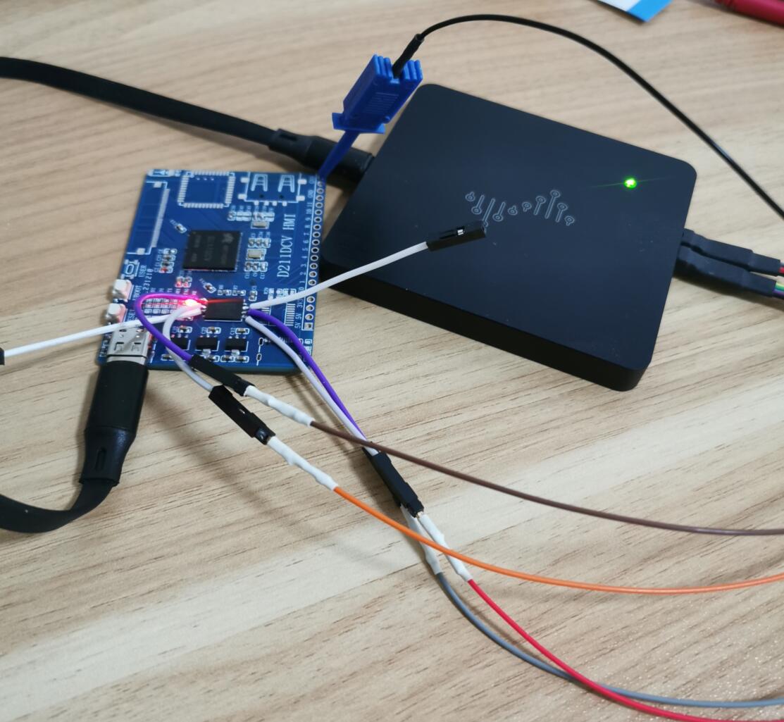
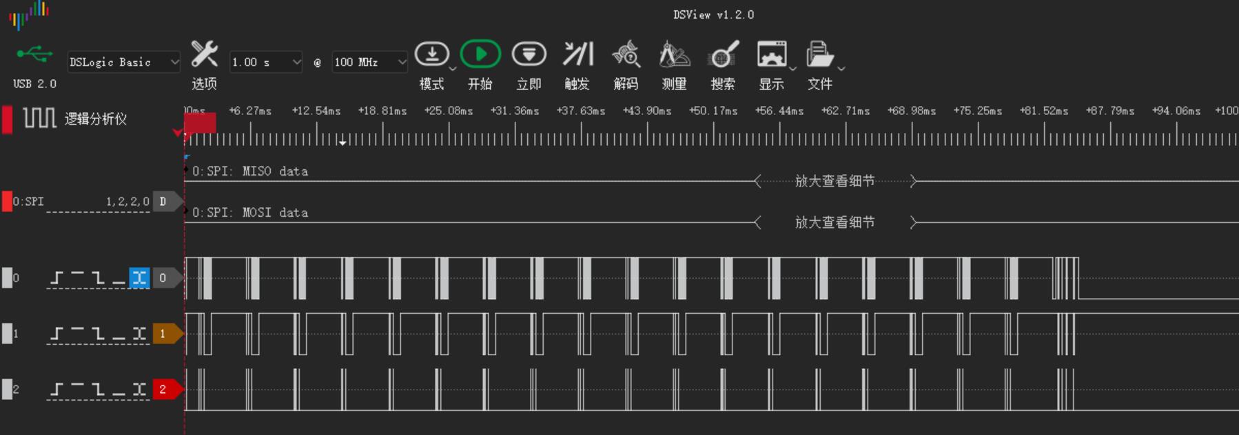

注意:100MHz 采样率下我的逻辑分析仪只能抓取 3 个信号,,所以未抓取 MISO 信号,,请忽略
然后AiBurn中按下“开始”按钮,,烧录失败,,log 内容如下,,但烧录过程中 SPI0 上完全没有任何信号,,请问这个是什么原因??
[debug] Software Version: "1.3.4"
[debug] Machine Name: "WMX-PC"
[debug] System Name: "Windows 10 (10.0)"
[debug] CPU Architecture: "x86_64"

[debug] Parse the image header from "C:/Users/WMX/Desktop/d211_demo100_nand_page_2k_block_128k_v1.0.0.img"
[debug] Soc type: "d211"
[debug] Board type: "demo100_nand_page_2k_block_128k"
[debug] Image version: "1.0.0"
[debug] Storage type: "spi-nand"
[debug] Storage ID: "P=2K,B=128K"
[debug] Meta count: "13"

[debug] Refresh the partition tree ...
[debug] Part name: image.target.spl , size: 128528
[debug] Part name: image.target.uboot , size: 826603
[debug] Part name: image.target.env , size: 16384
[debug] Part name: image.target.logo , size: 141709
[debug] Part name: image.target.kernel , size: 7721688
[debug] Part name: image.target.recovery , size: 10173439
[debug] Part name: image.target.rootfs , size: 29585408

[debug] Current connect type: 0
[debug] There are "1" device available

[debug] Try to connect the ArtInChip device "1:2" ...
[debug] Try to get Usb device hd info...
[debug] Get Usb device hd info success
[debug] The status of ArtInChip device: true
[debug] Start burn online ...
[debug] Progress range: 0 ~ 49743872

[debug] Burn Image file "C:/Users/WMX/Desktop/d211_demo100_nand_page_2k_block_128k_v1.0.0.img" ...

[debug] Meta 0 image.updater.ddr , size 27408 ...
[debug] Blocksize 4 , chunk 1048576 * 0 , rest 27408
[debug] Offset: 8704 Size: 27408
[debug] Dev "1:2" Send the rest data 27408
[debug] Don't check the result of image.updater.ddr

[debug] Meta 1 image.updater.env , size 16384 ...
[debug] Blocksize 4 , chunk 1048576 * 0 , rest 16384
[debug] Offset: 37376 Size: 16384
[debug] Dev "1:2" Send the rest data 16384

[debug] Meta 2 image.updater.uboot , size 826603 ...
[debug] Blocksize 4 , chunk 1048576 * 0 , rest 826603
[debug] Offset: 53760 Size: 826603
[debug] Dev "1:2" Send the rest data 826603

[debug] Meta 3 image.updater.logo , size 141709 ...
[debug] Blocksize 4 , chunk 1048576 * 0 , rest 141709
[debug] Offset: 881152 Size: 141709
[debug] Dev "1:2" Send the rest data 141709

[debug] Meta 4 image.updater.spl , size 128528 ...
[debug] Blocksize 4 , chunk 1048576 * 0 , rest 128528
[debug] Offset: 1024512 Size: 128528
[debug] Dev "1:2" Send the rest data 128528
[debug] Don't check the result of image.updater.spl

[debug] Meta 5 image.info , size 2048 ...
[debug] Blocksize 4 , chunk 1048576 * 0 , rest 2048
[debug] Offset: 0 Size: 2048
[debug] Dev "1:2" Send the rest data 2048

[debug] Meta 6 image.target.spl , size 128528 ...
[error] The status of device "1:2" error
[warn ] Try to resend firmware component image.target.spl , try count: 1
[warn ] Try to recovery the connection
[warn ] Resend firmware component: image.target.spl
[error] The status of device "1:2" error
[debug] Update "fail_cnt" of "2023-12-16"#58 工业芯 匠芯创 » 麻烦各位大神帮忙看下我的 AP6212 连线是否有问题,,谢谢。。 » 2023-12-04 23:47:19
- XIVN1987
- 回复: 3
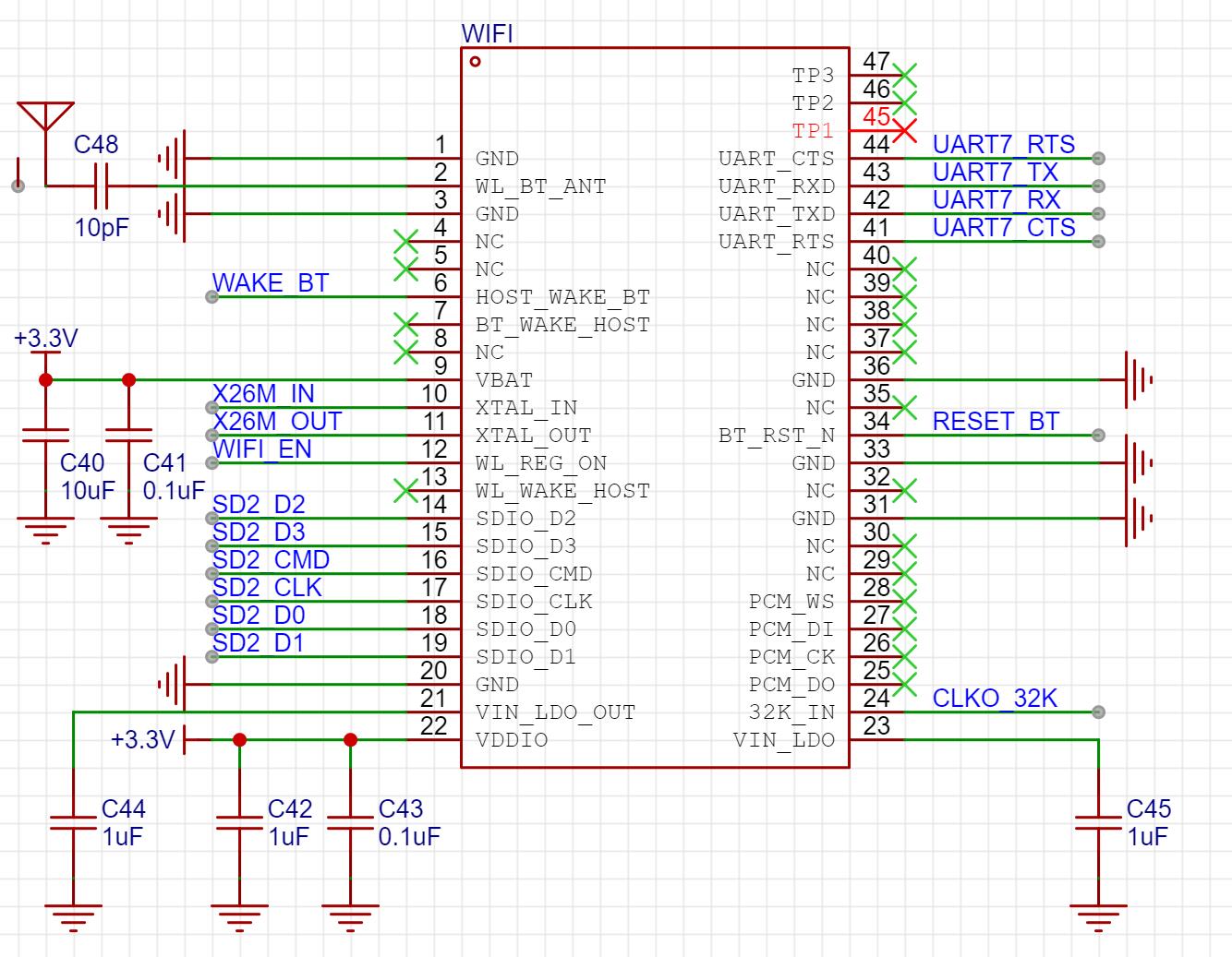
第一次用 WiFi 模块,,不太懂到底需要连哪些信号、可以不连哪些信号,,参考了 OrangePi 3B 等板子的原理图,,画图如下:
现在主要有三个疑惑:
1、BT_WAKE_HOST、WL_WAKE_HOST 是否可以不接??看名字这两个信号和唤醒有关,,那如果主机不休眠,,那是否就不需要被唤醒了?
2、天线连接是否正确,,我选的陶瓷天线,,引脚 1 通过 10pF 电容连接 AP6212 的 WL_BT_ANT 引脚,,引脚 2 悬空
3、VIN_LDO、VIN_LDO_OUT 是否可以悬空不接,,我看有些原理图上是悬空,,有些原理图上是接 10uF 电容。。
官方的产品规格书上也没有推荐的应用电路,,这些疑惑都无处可查,,哪位大神知道麻烦指点下,,谢谢。。
#61 Re: DIY/综合/Arduino/写字机/3D打印机/智能小车/平衡车/四轴飞行/MQTT/物联网 » 正点原子出逻辑分析仪了,,和DSLogic一样,也是基于 sigrok 开源解码方案。。 » 2023-07-21 17:38:58
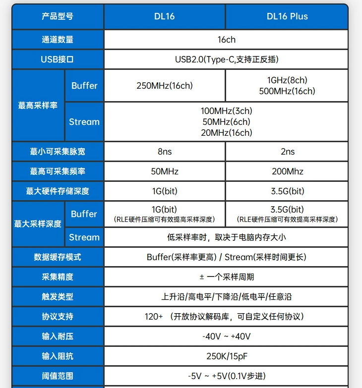
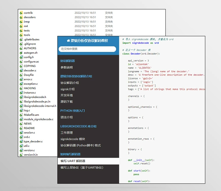
#62 DIY/综合/Arduino/写字机/3D打印机/智能小车/平衡车/四轴飞行/MQTT/物联网 » 正点原子出逻辑分析仪了,,和DSLogic一样,也是基于 sigrok 开源解码方案。。 » 2023-07-21 11:04:39
#63 Re: DIY/综合/Arduino/写字机/3D打印机/智能小车/平衡车/四轴飞行/MQTT/物联网 » 【新玩具get】AGM AGRV2K,16.8块钱的MCU+FPGA二合一芯片 » 2023-07-10 13:55:06
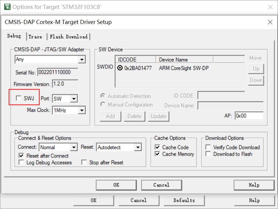
#64 Re: Cortex M0/M3/M4/M7 » Keil 通过 DAPLink 连结 STM32F411 时,不发送 JTAG-to-SWD 序列。。 » 2023-07-05 19:03:02
#66 Cortex M0/M3/M4/M7 » DAPLink 连接 STM32F411 奇怪现象:接线某个 GND 时连接失败。。 » 2023-07-05 14:54:37
- XIVN1987
- 回复: 3
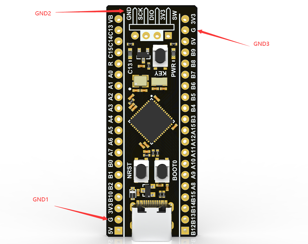
实验环境如下:DAPLink 是 MuseLab 的 nanoDAP v2.35,,STM32F411 测试板是 WeAct Studio 的 STM32F411CE 核心板 V3.1。
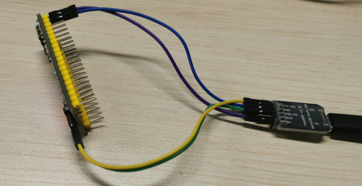
如下图,,这个板子有三个 GND,,测试发现,,当连接板子的 GND1 时,无法连接内核,,当连接板子的 GND2、GND3 时,,很容易连接内核
我测了下,,这三个 GND 之间的电阻只有 1 欧姆,,可以认为是连接良好的。。搞不懂为什么会出现这种现象,,
另外,,所还用 PyOCD 作为上位机连接过板子,,接 GND1 连接失败时报错如下:
(vexe) D:\Python38\vexe\Scripts>pyocd cmd -t stm32f412xe
0001519 E Error while initing target: Unexpected ACK value (5) returned by probe [commander]#67 Cortex M0/M3/M4/M7 » Keil 通过 DAPLink 连结 STM32F411 时,不发送 JTAG-to-SWD 序列。。 » 2023-07-04 21:44:35
- XIVN1987
- 回复: 2
如题,使用 Keil 连接芯片时失败,,通过逻辑分析仪抓 SWD 上的波形发现,,DAPLink 执行 Line reset 之后,,就直接发了 8 个 0,,然后就开始读取 IDCODE 了,,没有发送 JTAG-to-SWD 序列。。
根据网上找到的《Programming Internal Flash Over the Serial Wire Debug Interface》中如下内容,,调试器需要发送 JTAG-to-SWD 序列激活 SW-DP,,才能发送 SWD 命令。。

有两种可能导致这个问题:
1、Keil 让 DAPLink 发送 JTAG-to-SWD 序列了,,但 DAPLink 没发
2、Keil 就没让 DAPLink 发送 JTAG-to-SWD 序列
为了区分这两种情况,,我用 WireShark 抓取了一下 DAPLink 的 USB 数据,如下图所示,,结果发现 Keil 确实没让 DAPLink 发送 JTAG-to-SWD 序列。。
请问哪位大佬知道这是什么情况??是 Keil Bug 吗??我用的 Keil 版本是 5.36,,很新的版本,,感觉不应该出现这种 Bug 才对。。
最后,我上传了 WireShark 抓到的数据包,,感兴趣的大侠可以看看。。谢谢。。
WireShark_DAPLink_No_Jtag2SWD.rar
发送 Line reset:
发送 8 个 0:
#70 Re: DIY/综合/Arduino/写字机/3D打印机/智能小车/平衡车/四轴飞行/MQTT/物联网 » 【新玩具get】AGM AGRV2K,16.8块钱的MCU+FPGA二合一芯片 » 2023-06-23 22:42:18
#71 Re: DIY/综合/Arduino/写字机/3D打印机/智能小车/平衡车/四轴飞行/MQTT/物联网 » 【新玩具get】AGM AGRV2K,16.8块钱的MCU+FPGA二合一芯片 » 2023-06-13 09:38:02
#72 Re: Cortex M0/M3/M4/M7 » DAPLink添加WINUSB支持。。 » 2023-06-01 23:02:11
#73 Re: Cortex M0/M3/M4/M7 » DAPLink添加WINUSB支持。。 » 2023-05-31 22:47:47
#74 Re: Cortex M0/M3/M4/M7 » DAPLink添加WINUSB支持。。 » 2023-05-30 19:28:14
#75 Re: Cortex M0/M3/M4/M7 » DAPLink添加WINUSB支持。。 » 2023-05-29 22:09:53
#76 Re: Cortex M0/M3/M4/M7 » DAPLink添加WINUSB支持。。 » 2023-05-26 12:00:05
@XIVN1987,大佬太牛了;ch32v305的工程编译后在307的demo板上跑了一下,好像虚拟串口用不起来,不知是什么原因,请看下
我用的测试板是自己画的,,你可以对比下看看:https://oshwhub.com/xivn1987/ch32v307
#77 Re: Cortex M0/M3/M4/M7 » DAPLink添加WINUSB支持。。 » 2023-05-26 11:57:20
#78 Re: Cortex M0/M3/M4/M7 » 国产M7来了,分享datasheet » 2023-05-12 13:46:47
XIVN1987 说:USBHS 集成了 HS PHY,,牛啊,,这点比 STM32H7 强多了
还好吧,CH32V307早都支持了
STM32H7 不支持。。
#79 Re: Cortex M0/M3/M4/M7 » 国产M7来了,分享datasheet » 2023-05-11 21:48:50
#80 Re: PikaPython(嵌入式Python引擎) » 我希望在python中直接访问C语言的全局变量,直接通个python修改或者读取变量,而不通过方法,有什么办法可以实现吗? » 2023-04-21 09:37:53
https://docs.python.org/3/library/ctypes.html#accessing-values-exported-from-dlls
Accessing values exported from dlls
Some shared libraries not only export functions, they also export variables. An example in the Python library itself is the Py_OptimizeFlag, an integer set to 0, 1, or 2, depending on the -O or -OO flag given on startup.
ctypes can access values like this with the in_dll() class methods of the type. pythonapi is a predefined symbol giving access to the Python C api:
opt_flag = c_int.in_dll(pythonapi, "Py_OptimizeFlag")
print(opt_flag)
c_long(0)#82 Re: 全志 SOC » spi nand flash有什么优点和缺点呢? » 2023-03-23 17:37:34
#83 Re: 全志 SOC » spi nand flash有什么优点和缺点呢? » 2023-03-23 11:37:42
刚刚看到一个磨损均衡的库:https://github.com/azure-rtos/levelx
所以说,,磨损均衡还是挺复杂的,,
#84 Re: 全志 SOC » spi nand flash有什么优点和缺点呢? » 2023-03-23 11:34:07
#86 Re: Cortex M0/M3/M4/M7 » 求个推荐,内置高速USB(速度480 Mb/s)PHY的单片机 » 2023-02-10 10:04:56
CH32V305 主频 144MHz、128KB Flash、32KB RAM、TSSOP20 封装、内置 HSUSB PHY、价格 10 块左右,,完美符合楼主的需求了。。
虽然不是 Cortex-M 内核,,但 RISC-V 也不是冷门内核,,现在用的厂家越来越多了,,比如知名WiFi SoC厂商乐鑫之前用的Xtensa ISA,现在出的芯片大多是RISC-V内核的了(ESP32-C2/3/5/6、H2、P4)
前段儿时间用 CH32V305 移植了下 DAPLink (https://github.com/XIVN1987/DAPLink),,用起来感觉和 STM32 那些差别也不大(毕竟都是用 C 语言编程,,又不需要手写汇编),,MounRiver Studio 用起来也还行,,跟 Keil 相比各有长短吧。。
#87 Re: RISC-V » CH32V系列非0等待区使用及简陋的性能测试 » 2023-01-30 15:31:00
#90 Re: Cortex M0/M3/M4/M7 » Tiny-DAPLink:开源CH552实现的CMSIS-DAP v2升级版 » 2023-01-26 22:05:26
CH32V203F8 3块钱,可以跑到 144MHz,也支持 crystall-less USB。。
如果不想用 RISC-V 的话,,AT32F425F8 3.75元,Cortex-M4 内核,96MHz,,同样支持 crystall-less USB。。
原理图 & PCB:https://oshwhub.com/xivn1987/daplink
源代码:https://github.com/XIVN1987/DAPLink
#91 Re: Cortex M0/M3/M4/M7 » DAPLink添加WINUSB支持。。 » 2023-01-20 21:07:21
#92 Re: Cortex M0/M3/M4/M7 » DAPLink添加WINUSB支持。。 » 2023-01-12 21:55:11
#93 Re: RISC-V » RISC-V不支持非对齐地址访问非常坑 » 2023-01-05 18:12:20
#94 Re: RISC-V » RISC-V不支持非对齐地址访问非常坑 » 2023-01-05 18:08:31
#96 Re: RISC-V » 最权威的 RISC-V 汇编程序员手册 » 2022-11-24 19:16:09
#97 Re: RISC-V » 开源一个AB32VG1的开发板 » 2022-11-24 16:37:45
#98 Re: RISC-V » 国产riscv芯片汇总 » 2022-11-14 11:42:39
#99 Re: RISC-V » CH32V307内置SPI FLASH来自普冉 » 2022-11-13 15:50:53
#100 Re: RISC-V » 国产riscv芯片汇总 » 2022-11-10 16:09:06
#101 Re: RISC-V » RISC-V核心的SoC有没有已经在产品上广泛使用的型号? » 2022-11-08 20:39:54
#102 Re: RISC-V » RISC-V核心的SoC有没有已经在产品上广泛使用的型号? » 2022-11-08 16:22:30
#103 Re: RISC-V » RISC-V核心的SoC有没有已经在产品上广泛使用的型号? » 2022-11-08 09:30:24
#104 Re: RISC-V » 博流智能将要推出杀手级芯片bl808(可以跑linux) » 2022-11-03 10:16:28
#105 Re: DIY/综合/Arduino/写字机/3D打印机/智能小车/平衡车/四轴飞行/MQTT/物联网 » TinyUSer,极致体积的USB转串口小板,基于沁恒CH340X » 2022-11-02 10:25:33
#106 Re: RISC-V » 博流智能将要推出杀手级芯片bl808(可以跑linux) » 2022-10-27 20:59:45
#108 Re: RISC-V » WCH又搞了个性价比王炸CH32V003 » 2022-10-17 11:26:17
#109 Re: VMWare/Linux/Ubuntu/Fedora/CentOS/U-BOOT » 辣鸡向日葵,花了9元买了一个月的会员,却什么都干不了。我现在自己动手,用FRP这个优秀的开源软件把内网穿透搭起来了 » 2022-09-19 09:41:46
#110 Re: VMWare/Linux/Ubuntu/Fedora/CentOS/U-BOOT » R5S 运行 Debian 配置成软路由,NAT 不工作,,求教怎么改。。 » 2022-09-18 21:49:01
问题解决了,,解决方法是在 /etc/dhcp/dhcpd.conf 中下面的 subnet 配置中添加 routers 和 domain-name-servers 设置
subnet 192.168.2.0 netmask 255.255.255.0 {
 range 192.168.2.10 192.168.2.250;
 option routers 192.168.2.1;
 option domain-name-servers 8.8.8.8;
}
routers 选项用来设置接入设备的默认网关,这样接入设备就能 ping 通外网 IP 了。。
domain-name-servers 选项用来设置接入设备的域名解析服务器,之前由于笔记本通过 WiFi 获取的 DNS 是主路由的 IP,因此我也将上面的 DNS 设置成了 br-lan 的 IP,,结果发现不能 ping 通域名,,改成 8.8.8.8 就可以了。。
#111 Re: VMWare/Linux/Ubuntu/Fedora/CentOS/U-BOOT » R5S 运行 Debian 配置成软路由,NAT 不工作,,求教怎么改。。 » 2022-09-18 15:24:40
补充,,iptable 规则如下:
root@Armbian:~# iptables -nvL
Chain INPUT (policy ACCEPT 0 packets, 0 bytes)
 pkts bytes target     prot opt in     out     source               destination

Chain FORWARD (policy ACCEPT 0 packets, 0 bytes)
 pkts bytes target     prot opt in     out     source               destination
    0     0 ACCEPT     all  --  br-lan wifi0   0.0.0.0/0            0.0.0.0/0
    0     0 ACCEPT     all  --  wifi0  br-lan  0.0.0.0/0            0.0.0.0/0            ctstate RELATED,ESTABLISHED

Chain OUTPUT (policy ACCEPT 0 packets, 0 bytes)
 pkts bytes target     prot opt in     out     source               destination

root@Armbian:~# iptables -t nat -nvL
Chain PREROUTING (policy ACCEPT 0 packets, 0 bytes)
 pkts bytes target     prot opt in     out     source               destination

Chain INPUT (policy ACCEPT 0 packets, 0 bytes)
 pkts bytes target     prot opt in     out     source               destination

Chain POSTROUTING (policy ACCEPT 0 packets, 0 bytes)
 pkts bytes target     prot opt in     out     source               destination
    0     0 MASQUERADE  all  --  *      wifi0   0.0.0.0/0            0.0.0.0/0

Chain OUTPUT (policy ACCEPT 0 packets, 0 bytes)
pkts bytes target prot opt in out source destination#112 Re: VMWare/Linux/Ubuntu/Fedora/CentOS/U-BOOT » R5S 运行 Debian 配置成软路由,NAT 不工作,,求教怎么改。。 » 2022-09-18 11:24:35
执行 ipconfig /all 打印如下,,看起来设置都正常的,,没发现什么问题
无线局域网适配器 WLAN 3:

   连接特定的 DNS 后缀 . . . . . . . : lan
   描述. . . . . . . . . . . . . . . : Intel(R) Wi-Fi 6 AX200 160MHz
   物理地址. . . . . . . . . . . . . : 64-BC-58-05-05-9B
   DHCP 已启用 . . . . . . . . . . . : 是
   自动配置已启用. . . . . . . . . . : 是
   IPv6 地址 . . . . . . . . . . . . : fd88:88b7:3d35:0:6584:d263:af42:295e(首选)
   临时 IPv6 地址. . . . . . . . . . : fd88:88b7:3d35:0:a5a8:3e7b:b0f4:5beb(首选)
   本地链接 IPv6 地址. . . . . . . . : fe80::6584:d263:af42:295e%11(首选)
   IPv4 地址 . . . . . . . . . . . . : 192.168.18.107(首选)
   子网掩码  . . . . . . . . . . . . : 255.255.255.0
   获得租约的时间  . . . . . . . . . : 2022年9月18日 6:28:28
   租约过期的时间  . . . . . . . . . : 2022年9月18日 23:16:11
   默认网关. . . . . . . . . . . . . : 192.168.18.1
   DHCP 服务器 . . . . . . . . . . . : 192.168.18.1
   DHCPv6 IAID . . . . . . . . . . . : 577027160
   DHCPv6 客户端 DUID  . . . . . . . : 00-01-00-01-28-4B-DA-A9-80-30-49-2D-36-C5
   DNS 服务器  . . . . . . . . . . . : 192.168.18.1
   TCPIP 上的 NetBIOS  . . . . . . . : 已启用
   连接特定的 DNS 后缀搜索列表:
                                       lan

以太网适配器 以太网 3:

   连接特定的 DNS 后缀 . . . . . . . : example.org
   描述. . . . . . . . . . . . . . . : ASIX AX88179A USB 3.2 Gen1 to Gigabit Ethernet Adapter
   物理地址. . . . . . . . . . . . . : F8-E4-3B-5B-2C-46
   DHCP 已启用 . . . . . . . . . . . : 是
   自动配置已启用. . . . . . . . . . : 是
   本地链接 IPv6 地址. . . . . . . . : fe80::f474:2cd3:a8c:c01e%19(首选)
   IPv4 地址 . . . . . . . . . . . . : 192.168.2.10(首选)
   子网掩码  . . . . . . . . . . . . : 255.255.255.0
   获得租约的时间  . . . . . . . . . : 2022年9月18日 11:12:34
   租约过期的时间  . . . . . . . . . : 2022年9月18日 11:27:27
   默认网关. . . . . . . . . . . . . : 192.168.2.1
   DHCP 服务器 . . . . . . . . . . . : 192.168.2.1
   DHCPv6 IAID . . . . . . . . . . . : 922281019
   DHCPv6 客户端 DUID  . . . . . . . : 00-01-00-01-28-4B-DA-A9-80-30-49-2D-36-C5
   DNS 服务器  . . . . . . . . . . . : 192.168.2.1
   TCPIP 上的 NetBIOS  . . . . . . . : 已启用
ip、gateway、dns 服务器都设置了,,可笔记本只连 r5s lan 口的时候就是无法 ping 通外网,,不知道还有哪里设置不对。。
#113 VMWare/Linux/Ubuntu/Fedora/CentOS/U-BOOT » R5S 运行 Debian 配置成软路由,NAT 不工作,,求教怎么改。。 » 2022-09-18 00:59:24
- XIVN1987
- 回复: 4
/etc/network/interfaces 配置如下:
auto eth0
iface eth0 inet dhcp

auto wifi0
iface wifi0 inet dhcp
    wpa-essid xxxxxxxxxx
    wpa-psk xxxxxxxxxx

auto br-lan
iface br-lan inet static
    address 192.168.2.1
    network 192.168.2.0
    netmask 255.255.255.0
    broadcast 192.168.2.255
    bridge-ports eth1 eth2
R5S 通过 USB WiFi 连接主路由,,配置 dhcpd 监听网桥 br-lan,,笔记本通过网线连接 R5S LAN 口
这样配置后,,R5S 通过 WiFi 联通互联网成功,,笔记本分配局域网地址成功,,
接下来只需要配置好 NAT,,笔记本应该就能通过 R5S 联通互联网了,,根据网上搜到的资料,NAT 配置代码如下:
EXTIF="wifi0"
INTIF="br-lan"

echo 1 > /proc/sys/net/ipv4/ip_forward

iptables -t nat --flush
iptables -t filter --flush

iptables -t nat -A POSTROUTING -o "$EXTIF" -j MASQUERADE

# Allow traffic from internal to external
iptables -A FORWARD -i "$INTIF" -o "$EXTIF" -j ACCEPT
# Allow returning traffic from external to internal
iptables -A FORWARD -i "$EXTIF" -o "$INTIF" -m conntrack --ctstate ESTABLISHED,RELATED -j ACCEPT
但我执行上述代码后,,笔记本以太网显示“无 Internet”,,笔记本上 ping 192.168.2.1 能 ping 通,,但 ping 192.168.18.1(主路由器IP)ping 不通,,请教我哪里配置有问题?该怎么解决??多谢大侠指教。。
#119 Re: GM8135s/GM8136s/GM8135/GM8136/GM8125/GM8126 » GM8135S还在正常出货吗?或者还有其他类似的吗? » 2022-08-17 13:55:31
#120 Re: 全志 SOC » 使用rust对arm9处理器进行裸机开发 » 2022-07-08 10:28:10
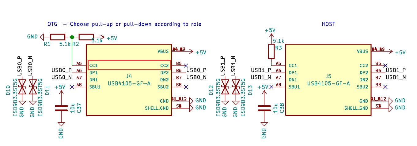
#121 Re: 全志 SOC » USB Type-C 如何实现 OTG? » 2022-06-24 13:36:01
#122 Re: 全志 SOC » USB Type-C 如何实现 OTG? » 2022-06-24 13:15:11
#123 Re: 全志 SOC » USB Type-C 如何实现 OTG? » 2022-06-24 12:59:51
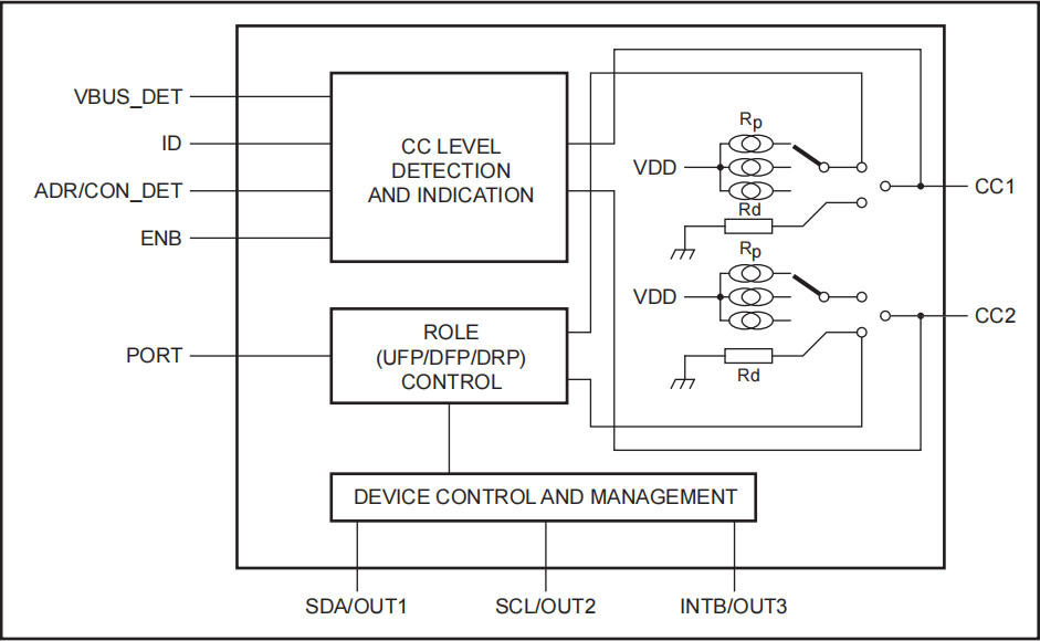
基本搞清楚了,,好像是需要使用专门的芯片才能实现,比如NXP的 PTN5150
基本原理猜测是:上电 CC1/CC2 引脚悬空,当主机接入时,CC1/CC2 会被主机端上拉电阻拉高;从从机接入时,CC1/CC2 会被从机端下拉电阻拉低,这样就能检测到连接,并能区分出对方是主机还是从机。
区分出以后,若对方是主机,则 PTN5150 将 CC1/CC2 下拉,将自己配置成从机;若对方是从机,则 PTN5150 将 CC1/CC2 上拉,将自己配置成主机。完成主从连接。
另外,这个芯片还通过 ID 引脚输出自己主从模式,传统的 USB 2.0 OTG 的 ID 脚可连接此引脚,得知 PTN5150 的检测结果。
#125 Re: RISC-V » 性能最强的 RISC-V 内核单片机:HPM6750 » 2022-05-13 20:06:44
#126 Re: RISC-V » 性能最强的 RISC-V 内核单片机:HPM6750 » 2022-05-13 18:08:42
#127 Re: RISC-V » 性能最强的 RISC-V 内核单片机:HPM6750 » 2022-05-11 11:16:14
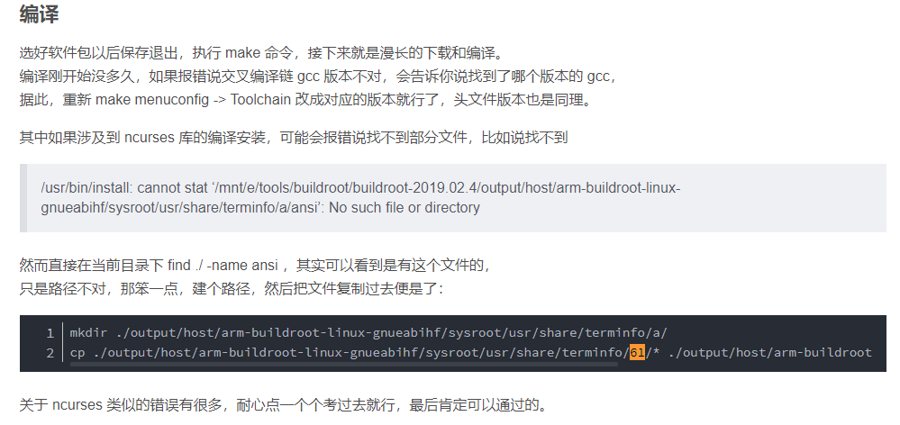
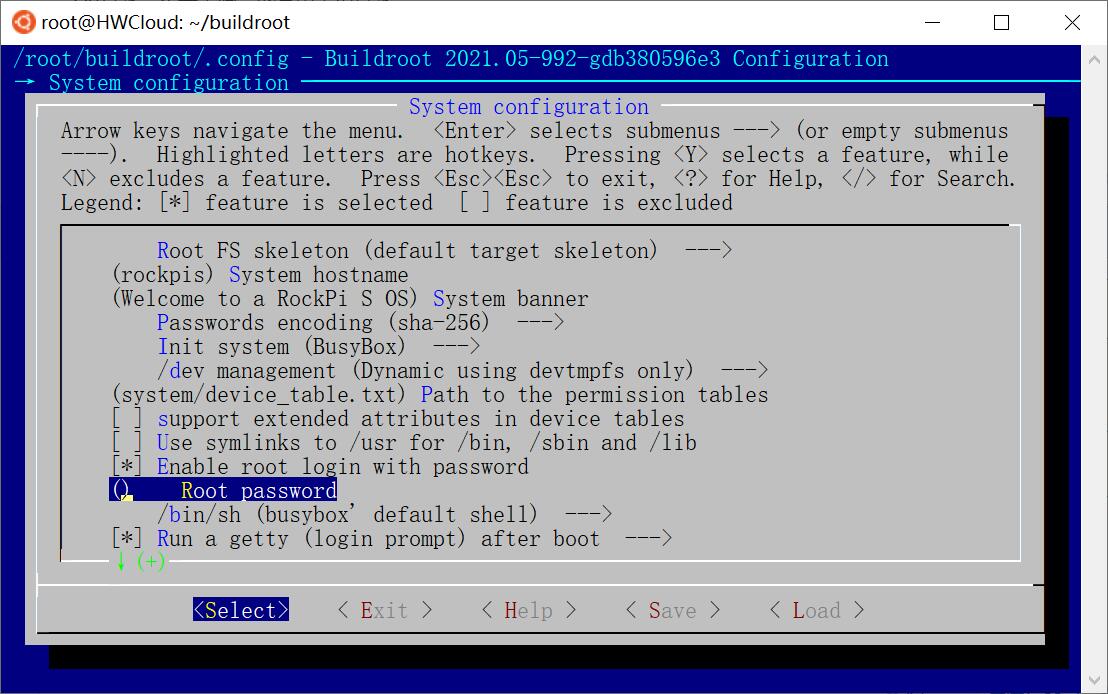
#128 Re: RK3288/RK3399/RK1108 » WSL下编译buildroot,sysroot/usr/share/terminfo 下的目录名都是 ASCII 码,请问怎么解决? » 2022-05-11 11:02:44
编译完成了,,成功生成了 sdcard.img,,
没有遇到其他网友说的需要“用fakeroot-tcp替换fakeroot-sysv”的问题
过程还算顺利,,就遇到两个问题,,除了楼上那个问题,,另一个是 WSL 中 Ubuntu 的 PATH 会包含 Windows 的 PATH,,而 Windows 的 PATH 路径可能包含空格,,导致编译出错,,解放方法是使用 “PATH=/usr/local/sbin:/usr/local/bin:/usr/sbin:/usr/bin:/sbin:/bin make” 临时覆盖 PATH
看起来 WSL 下编译 Buildroot 还是可行的。。
#129 Re: RISC-V » 性能最强的 RISC-V 内核单片机:HPM6750 » 2022-05-11 10:04:53
#131 Re: RISC-V » 与 ARM 相比,Risc-V 有多好? » 2022-05-11 09:49:03
#132 Re: 全志 SOC » YuzukiCK1N - 基于全志V3x的触屏小电脑【开源硬件】 » 2022-05-11 09:15:54
#133 Re: RK3288/RK3399/RK1108 » WSL下编译buildroot,sysroot/usr/share/terminfo 下的目录名都是 ASCII 码,请问怎么解决? » 2022-05-11 00:37:35
还没有找到目录名变成数字的根源,暂时想到一个方法避免手动拷贝,,先走通编译流程吧
找到 buildroot\package\ncurses\ncurses.mk 中如下内容:
define NCURSES_TARGET_CLEANUP_TERMINFO
	$(RM) -rf $(TARGET_DIR)/usr/share/terminfo $(TARGET_DIR)/usr/share/tabset
	$(foreach t,$(NCURSES_TERMINFO_FILES), \
		$(INSTALL) -D -m 0644 $(STAGING_DIR)/usr/share/terminfo/$(t) \
			$(TARGET_DIR)/usr/share/terminfo/$(t)
	)
endef
可知,第一个 $(t) 指定源地址,第二个 $(t) 指定目的地址,只需要将第一个 $(t) 的第一个字符转换成其 ASCII 码数字应该就可以编译了
不懂 shell 怎么处理字符串,,用 python 处理,改成如下内容:
define NCURSES_TARGET_CLEANUP_TERMINFO
	$(RM) -rf $(TARGET_DIR)/usr/share/terminfo $(TARGET_DIR)/usr/share/tabset
	$(foreach t,$(NCURSES_TERMINFO_FILES), \
		$(INSTALL) -D -m 0644 $(STAGING_DIR)/usr/share/terminfo/$(shell python3 -c \
			"import sys; t = sys.argv[1]; t = f'{ord(t[0]):x}{t[1:]}'; print(t)" ${t}) \
			$(TARGET_DIR)/usr/share/terminfo/$(t)
	)
endef#134 Re: RK3288/RK3399/RK1108 » WSL下编译buildroot,sysroot/usr/share/terminfo 下的目录名都是 ASCII 码,请问怎么解决? » 2022-05-09 14:52:53
#135 Re: RK3288/RK3399/RK1108 » WSL下编译buildroot,sysroot/usr/share/terminfo 下的目录名都是 ASCII 码,请问怎么解决? » 2022-05-09 14:45:43
我现在想到的一个可能有效的办法是,修改 buildroot\package\ncurses\ncurses.mk 下的如下部分:
NCURSES_TERMINFO_FILES = \
	a/ansi \
	d/dumb \
	l/linux \
	p/putty \
	p/putty-256color \
	p/putty-vt100 \
	s/screen \
	s/screen-256color \
	v/vt100 \
	v/vt100-putty \
	v/vt102 \
	v/vt200 \
	v/vt220 \
	x/xterm \
	x/xterm+256color \
	x/xterm-256color \
	x/xterm-color \
	x/xterm-xfree86 \
	$(call qstrip,$(BR2_PACKAGE_NCURSES_ADDITIONAL_TERMINFO))
把其中的 a、d、l、p、s、v、x 等目录名改成其对应的 ASCII 码。。
但是我更想知道目录名是怎么变成 ASCII 码的,,在对应的位置修改,不让它变成 ASCII 码
#136 RK3288/RK3399/RK1108 » WSL下编译buildroot,sysroot/usr/share/terminfo 下的目录名都是 ASCII 码,请问怎么解决? » 2022-05-09 14:40:53
- XIVN1987
- 回复: 6
编译报错:
/usr/bin/install -D -m 0644 /mnt/d/Program/Ubuntu/buildroot/output/host/aarch64-buildroot-linux-uclibc/sysroot/usr/share/terminfo/a/ansi /mnt/d/Program/Ubuntu/buildroot/output/target/usr/share/terminfo/a/ansi
/usr/bin/install: cannot stat '/mnt/d/Program/Ubuntu/buildroot/output/host/aarch64-buildroot-linux-uclibc/sysroot/usr/share/terminfo/a/ansi': No such file or directory
查看 sysroot/usr/share/terminfo 下内容如下:
root@wmxpc:~/win/buildroot# ls /mnt/d/Program/Ubuntu/buildroot/output/host/aarch64-buildroot-linux-uclibc/sysroot/usr/share/terminfo/
31  34  37  41  4d  51  62  65  68  6b  6e  71  74  77
32  35  38  45  4e  58  63  66  69  6c  6f  72  75  78
33  36  39  4c  50  61  64  67  6a  6d  70  73  76  7a
似乎是把目录名 a 变成了它的 ASCII 码 61,,
请问这是什么导致的??怎么解决?
#141 Re: RK3288/RK3399/RK1108 » host-fakeroot patch出错,哪位大神知道怎么解决,,谢谢 » 2022-02-17 21:07:02
大概搞清楚了,,
buildroot/package/fakeroot/0002-libfakeroot.c-define-_STAT_VER-if-not-already-define.patch
和
buildroot.rockchip/patches.rockpis/fakeroot/0002.stat_ver.patch
中都有如下内容:
diff --git a/libfakeroot.c b/libfakeroot.c
index 3e80e38..14cdbc4 100644
--- a/libfakeroot.c
+++ b/libfakeroot.c
@@ -90,6 +90,16 @@
 #define SEND_GET_XATTR64(a,b,c) send_get_xattr64(a,b)
 #endif

+#ifndef _STAT_VER
+ #if defined (__aarch64__)
+  #define _STAT_VER 0
+ #elif defined (__x86_64__)
+  #define _STAT_VER 1
+ #else
+  #define _STAT_VER 3
+ #endif
+#endif
+
对同一位置完全相同的补丁,前一个打上,后一个肯定就打不上了,,删掉其中一个补丁就可以了
#142 RK3288/RK3399/RK1108 » host-fakeroot patch出错,哪位大神知道怎么解决,,谢谢 » 2022-02-17 12:15:30
- XIVN1987
- 回复: 2
编译命令如下:
git clone https://github.com/buildroot/buildroot.git
git clone https://github.com/flatmax/buildroot.rockchip.git

cd buildroot
make BR2_EXTERNAL=../buildroot.rockchip rockpis_defconfig

make menuconfig
# Toolchain 下 GCC compiler Version 由 gcc 10.x 改为 gcc 9.x

make
报错信息如下:
fakeroot_1.25.3.orig.tar.gz: OK (sha256: 8e903683357f7f5bcc31b879fd743391ad47691d4be33d24a76be3b6c21e956c)
>>> host-fakeroot 1.25.3 Extracting
gzip -d -c /root/buildroot.dl/fakeroot/fakeroot_1.25.3.orig.tar.gz | tar --strip-components=1 -C /root/buildroot/output/build/host-fakeroot-1.25.3   -xf -
>>> host-fakeroot 1.25.3 Patching

Applying 0001-skip-doc-subdirs.patch using patch:
patching file doc/Makefile.am

Applying 0002-libfakeroot.c-define-_STAT_VER-if-not-already-define.patch using patch:
patching file libfakeroot.c

Applying 0003-libfakeroot.c-add-wrappers-for-new-glibc-2.33-symbol.patch using patch:
patching file libfakeroot.c

Applying 0004-configure.ac-fix-__xmknod-at-pointer-argument.patch using patch:
patching file configure.ac

Applying 0005-fix-build-regression-on-macOS.patch using patch:
patching file configure.ac
patching file libfakeroot.c

Applying 0002.stat_ver.patch using patch:
patching file libfakeroot.c
Reversed (or previously applied) patch detected!  Skipping patch.
1 out of 1 hunk ignored -- saving rejects to file libfakeroot.c.rej
patching file libfakeroot.c
Hunk #1 succeeded at 1402 with fuzz 1 (offset 50 lines).
patching file libfakeroot.c
Hunk #1 succeeded at 2575 (offset 50 lines).
patching file configure.ac
Reversed (or previously applied) patch detected!  Skipping patch.
2 out of 2 hunks ignored -- saving rejects to file configure.ac.rej
patching file libfakeroot.c
Hunk #1 succeeded at 2116 (offset 50 lines).
Hunk #2 succeeded at 2135 (offset 50 lines).
patching file configure.ac
patching file libfakeroot.c
Hunk #4 succeeded at 2035 (offset 50 lines).
Hunk #5 succeeded at 2636 (offset 50 lines).
patching file wrapawk_macosx
patching file wrapfunc.inp
make: *** [package/pkg-generic.mk:227: /root/buildroot/output/build/host-fakeroot-1.25.3/.stamp_patched] Error 1#144 Re: Php/Nodejs/Web/HTML5/Javascript/微信开发/Python » Pyinstaller打包使用pyusb的python程序 » 2022-01-19 10:55:58
#145 Php/Nodejs/Web/HTML5/Javascript/微信开发/Python » Pyinstaller打包使用pyusb的python程序 » 2022-01-18 10:24:40
- XIVN1987
- 回复: 2
用Python写了个使用pyusb库的模仿JLink Commander的应用:https://github.com/XIVN1987/DAPCmdr
为了方便同事使用,于是用“pyinstaller -F path/to/DAPCmdr.py”将其打包成单个exe可执行文件,,
可是打包后程序执行报错“No backend available”,,无法发现和连接DAPLink,,根据之前调试pyusb的经验,,这是pyusb库找不到libusb.dll导致的
可是源码形式下可以找到libusb.dll,,为啥打包后就不行了呢??经过搜索和阅读源码发现,,原来pyinstaller修改了pyusb搜索libusb.dll的方式。。
pyusb原本的libusb.dll搜索代码执行流程如下:
_load_library() # usb\backend\libusb1.py
    usb.libloader.load_locate_library('libusb-1.0')

load_locate_library(name) # usb\libloader.py
    ctypes.util.find_library(name + '.dll')

find_library(name) # ctypes\util.py
    for directory in os.environ['PATH'].split(os.pathsep):
        fname = os.path.join(directory, name)
        if os.path.isfile(fname):
            return fname
简单来说pyusb最终是通过ctypes.util.find_library搜索libusb.dll的,,而ctypes.util.find_library是在环境变量PATH包含的路径下搜索libusb.dll的,,
我为了不修改系统变量PATH依然能够执行DAPCmdr.py,所以在DAPCmdr.py的起始处添加了下面一行代码:
os.environ['PATH'] = os.path.join(os.path.dirname(os.path.abspath(__file__)), 'libusb-1.0.24/MinGW64/dll') + os.pathsep + os.environ['PATH']也就是把DAPCmdr.py所在目录下的 libusb-1.0.24/MinGW64/dll 目录路径加入环境变量 PATH,这样 ctypes.util.find_library 就能从 DAPCmdr.py 所在路径下搜索到 libusb.dll,而且不管 DAPCmdr 目录拷贝到哪里,DAPCmdr.py 都能正常启动执行。。
而 Pyinstaller 打包使用 pyusb 库的程序时,会用到 site-packages\\_pyinstaller_hooks_contrib\\hooks\\rthooks\\pyi_rth_usb.py 文件,其内容如下:
def get_load_func(type, candidates):
    def _load_library(find_library=None):
        exec_path = sys._MEIPASS

        l = None
        for candidate in candidates:
            # Do linker's path lookup work to force load bundled copy.
            if sys.platform == 'win32' or sys.platform == 'cygwin':
                libs = glob.glob("%s\\%s*.dll" % (exec_path, candidate))
            else:
                libs = glob.glob("%s/%s*.so*" % (exec_path, candidate))
            for libname in libs:
                try:
                    l = ctypes.WinDLL(libname)
                    if l is not None:
                        break
                except:
                    l = None
            if l is not None:
                break
        else:
            raise OSError('USB library could not be found')

        return l
    return _load_library


import usb.backend.libusb1 as libusb10
libusb10._load_library = get_load_func('libusb10', ('usb-1.0', 'libusb-1.0', 'usb'))
可以看到,它用自己编写的 _load_library 函数替代了usb.backend.libusb1 自身的 _load_library 函数,,而它自己编写的 _load_library 是在打包生成的 DAPCmdr.exe 文件所在的目录下查找 libusb.dll 的。。
所以我按照源码目录结构把 libusb-1.0.24 文件夹拷贝到 DAPCmdr.exe 所在目录,,DAPCmdr.exe 执行时是无法搜索到 libusb.dll 的。。只有将 libusb-1.0.24 文件夹下的 libusb-1.0.dll 文件拷贝到 DAPCmdr.exe 所在目录,,DAPCmdr.exe 执行时才能搜索到 libusb.dll
#146 Re: Cortex M0/M3/M4/M7 » DAPLink添加WINUSB支持。。 » 2022-01-14 09:24:51
#147 Re: 全志 SOC » 开源D1s核心板+底板 » 2022-01-13 09:05:14
#148 Re: Cortex M0/M3/M4/M7 » DAPLink添加WINUSB支持。。 » 2022-01-12 22:08:22
DAPCmdr、MCUProg、RTTView三件套添加CMSIS-DAP v2支持,,感兴趣的可以mark下 ![]()
https://github.com/XIVN1987/DAPCmdr
https://github.com/XIVN1987/MCUProg
https://github.com/XIVN1987/RTTView
#149 Cortex M0/M3/M4/M7 » DAPLink添加WINUSB支持。。 » 2022-01-12 20:55:19
- XIVN1987
- 回复: 30
之前使用HID传输协议,下载速度比较慢,,所以升级添加了 WINUSB 协议支持,,
通过在Keil Option窗口C/C++页是否定义 DAP_FW_V1 宏,选择使用 HID 协议还是 WINUSB 协议。。
官方的 DAPLink 功能更多,,但代码也很多,,不易阅读,,我这个移植代码比较简洁,,容易读懂和移植,,感兴趣的可以看下
#150 Re: Cortex M0/M3/M4/M7 » 一个GD32的CAN外设硬件bug » 2022-01-05 17:35:06
#151 Re: Cortex M0/M3/M4/M7 » 一个GD32的CAN外设硬件bug » 2022-01-04 21:20:46
#152 Re: Cortex M0/M3/M4/M7 » DAPLink添加软件复位功能。。 » 2021-12-27 10:22:08
#153 Re: Cortex M0/M3/M4/M7 » DAPLink添加软件复位功能。。 » 2021-12-27 09:31:15
#154 Re: Cortex M0/M3/M4/M7 » DAPLink添加软件复位功能。。 » 2021-12-26 12:17:59
#155 Re: Cortex M0/M3/M4/M7 » DAPLink添加软件复位功能。。 » 2021-12-25 19:52:38
#156 Cortex M0/M3/M4/M7 » DAPLink添加软件复位功能。。 » 2021-12-25 18:54:24
- XIVN1987
- 回复: 20
最近使用DAPLink,发现即使在Keil下载设置中勾选了“Reset and Run”,下载后仍然不能自动复位执行,,需要手动按一下复位按键程序才能执行,,感觉比较麻烦。。所以就打算给DAPLink添加软件复位功能。。
查看DAPLink源码发现其中有 ID_DAP_ResetTarget 命令,该命令最终调用函数 RESET_TARGET,感觉只要在该函数中实现通过 SWD 向目标芯片的 SCB->AIRCR 寄存器写入复位请求即可实现复位目标芯片的功能,,代码如下:
extern uint8_t swd_write_word(uint32_t addr, uint32_t val);
static uint32_t RESET_TARGET(void)
{
	swd_write_word((uint32_t)&SCB->AIRCR, ((0x5FA << SCB_AIRCR_VECTKEY_Pos) | SCB_AIRCR_SYSRESETREQ_Msk));

    return 1;	// change to '1' when a device reset sequence is implemented
}
可是修改后发现,并不管用,,目标板并没有复位。。
通过Wireshark抓取Keil与DAPLink的通信过程发现,Keil并没有发送 ID_DAP_ResetTarget 命令,,而是通过 ID_DAP_SWJ_Pins 命令直接通过JTAG的nRESET引脚复位目标芯片。。可是我的DAPLink上没有nRESET引脚,,所以我在DAPLink响应 ID_DAP_SWJ_Pins 命令拉低 nRESET 引脚时执行 SCB->AIRCR 写入操作,,代码如下:
extern uint8_t swd_write_word(uint32_t addr, uint32_t val);
static __inline void PIN_nRESET_OUT(uint32_t bit)
{
	if(bit == 0)
	{
		swd_write_word((uint32_t)&SCB->AIRCR, ((0x5FA << SCB_AIRCR_VECTKEY_Pos) | SCB_AIRCR_SYSRESETREQ_Msk));
	}
}
这样,,不需要接nRESET引脚,,SWD下载后也能自动复位执行了。。
代码工程已经更新到github上,,感兴趣的可以看下:https://github.com/XIVN1987/DAPLink
#157 Re: 全志 SOC » 开源个D1s核心板 » 2021-12-24 21:23:15
#158 Re: 全志 SOC » 开源个D1s核心板 » 2021-12-24 21:20:55
#163 Re: Cortex M0/M3/M4/M7 » 分享我画的M482简易开发板,板载DAPLink! » 2021-12-19 00:22:27
问下楼主,DAPLink的烧录速度如何?我试了nu-link + OpenOCD的烧录速度太慢了才4KB/S,对比ST-Link还真不习惯。
实测如下:文件大小 426KB,总共耗时 21s,其中打印2000012D是在执行擦除,打印2000038D是在执行写入,,擦除和写入分别耗时10s,因此写入速度大概是40KB/s。。
我这个DAPLink是用的HID传输协议,全速模式下HID速度最高也就64B*1000/1024=62.5KB/s,考虑到待烧写数据传输到DAPLink后还需要通过SWD接口发送到目标芯片、目标芯片Flash写入也需要耗时,,因此40KB/s估计就是全速USB HID方案的烧写速度极限了。。
要想再快就只能使用CMSIS-DAP v2的WINUSB传输协议了,,采用这个协议理论上能够做到和J-Link、ST-Link一样快。。
另外,,关于擦除时间的问题,,感觉耗时比较长,,于是查了下
擦除1个页大概100ms,,426KB对应106个Flash页,,总共耗时100ms*106=10s,,和实测结果差不多
上面用到的烧录软件,感兴趣可以下载试试:https://github.com/XIVN1987/MCUProg
#164 Cortex M0/M3/M4/M7 » 分享我画的M482简易开发板,板载DAPLink! » 2021-12-18 21:45:48
- XIVN1987
- 回复: 3
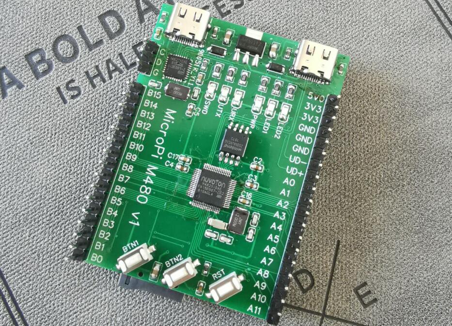
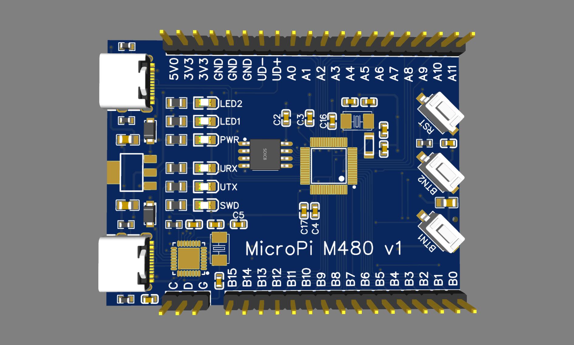
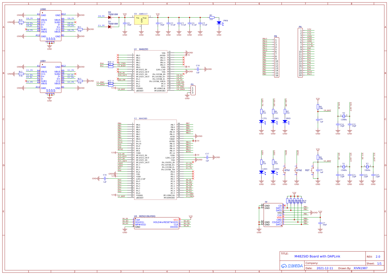
虽然Linux要学,,可单片机也不能丢弃,,所以画了块简单的单片机小板。。 ![]()
焊了一块测试了下,,基本功能没问题。。主控和DAPLink都能工作。。
MicroPi-M482 Github: https://github.com/XIVN1987/MicroPi-M482
MicroPi-M482 OSHWHub: https://oshwhub.com/XIVN1987/M482SIDv2
板载DAPLink的固件:https://github.com/XIVN1987/DAPLink
我给M482移植的MicroPython:https://github.com/XIVN1987/micropython/tree/master/ports/m480
#166 Php/Nodejs/Web/HTML5/Javascript/微信开发/Python » 分享我用PyQt编写的简易串口助手。。 » 2021-12-14 13:22:42
- XIVN1987
- 回复: 3
#167 Re: DIY/综合/Arduino/写字机/3D打印机/智能小车/平衡车/四轴飞行/MQTT/物联网 » 有人会把python2 的代码转exe吗?发现个dap能接收jlink-rtt的软件 » 2021-12-13 14:15:18
这个是新版,,同时支持Jlink和DAPLink(CMSIS-DAP)
https://github.com/XIVN1987/RTTView
https://github.com/XIVN1987/RTTView/releases/tag/20211213
#169 Re: 全志 SOC » 兄弟们,MangoPi-麻雀MQ已成功量产 » 2021-12-11 13:38:30
#171 Re: PikaPython(嵌入式Python引擎) » 【pikascript】超轻量级的跨平台嵌入式Python解释器,可以在STM32G030等小资源MCU运行 » 2021-12-02 17:14:58
#172 RK3288/RK3399/RK1108 » 编译 armbian,报错 chroot: failed to run command '/bin/bash': Exec format e » 2021-11-18 21:26:41
- XIVN1987
- 回复: 1
编译命令是:
git clone https://github.com/armbian/build armbian
docker run --name c_armbian -v /root/armbian:/armbian -it ubuntu:21.04 bash
apt install git
cd /armbian
./compile.sh BOARD=rockpi-s BRANCH=current RELEASE=buster KERNEL_ONLY=no KERNEL_CONFIGURE=no BUILD_MINIMAL=no BUILD_DESKTOP=no
主机环境是 Ubuntu 18.04.4,报错内容是:
[ o.k. ] Installing base system [ Stage 2/2 ]
chroot: failed to run command '/bin/bash': Exec format error
[ error ] ERROR in function create_rootfs_cache [ debootstrap.sh:212 ]
[ error ] Debootstrap base system for current rockpi-s buster   no second stage failed
[ o.k. ] Process terminated
[ o.k. ] Unmounting [ /armbian/.tmp/rootfs-f321cf67-d4eb-4870-ad36-1313933e4c67/ ]
[ error ] ERROR in function unmount_on_exit [ image-helpers.sh:82 ]
[ error ] debootstrap-ng was interrupted
[ o.k. ] Process terminated
这个是什么问题?怎么解决??求教大佬指点,,谢谢。。
#173 Re: RK3288/RK3399/RK1108 » 编译 armbian,报错缺少 binfmt_misc » 2021-11-18 17:45:17
docker用的还是原内核,解决不了内核模块问题。必须在本机加载这个模块才行。
感谢指点,确实如此,,
只要在本地主机安装了 binfmt_misc 内核模块,在 docker 容器中就能看到,,我一直以为需要在 docker 容器中执行 modprobe 安装模块,,原来是不需要的
root@HWCloud:~# modprobe binfmt_misc

root@HWCloud:~# docker container attach c_armbian

root@91565d9071de:/armbian# modprobe binfmt_misc
modprobe: FATAL: Module binfmt_misc not found in directory /lib/modules/4.15.0-91-generic

root@91565d9071de:/armbian# lsmod
Module                  Size  Used by
binfmt_misc            20480  1
veth                   16384  0
xt_conntrack 16384 1#174 Re: RK3288/RK3399/RK1108 » 编译 armbian,报错缺少 binfmt_misc » 2021-11-17 22:26:05
试试 apt install binfmt-support
binfmt_misc 在 binfmt-support 中吗?
root@91565d9071de:/armbian# apt install binfmt-support
Reading package lists... Done
Building dependency tree... Done
Reading state information... Done
binfmt-support is already the newest version (2.2.1-1).
0 upgraded, 0 newly installed, 0 to remove and 0 not upgraded.

root@91565d9071de:/armbian# modprobe binfmt_misc
modprobe: FATAL: Module binfmt_misc not found in directory /lib/modules/4.15.0-91-generic#175 RK3288/RK3399/RK1108 » 编译 armbian,报错缺少 binfmt_misc » 2021-11-17 21:21:14
- XIVN1987
- 回复: 4
我的编译命令如下:
git clone https://github.com/armbian/build armbian
docker run --name c_armbian -v /root/armbian:/armbian -it ubuntu:21.04 bash
apt install git
cd /armbian
./compile.sh BOARD=rockpi-s BRANCH=current RELEASE=buster KERNEL_ONLY=no KERNEL_CONFIGURE=no BUILD_MINIMAL=no BUILD_DESKTOP=no
官方的编译要求如下: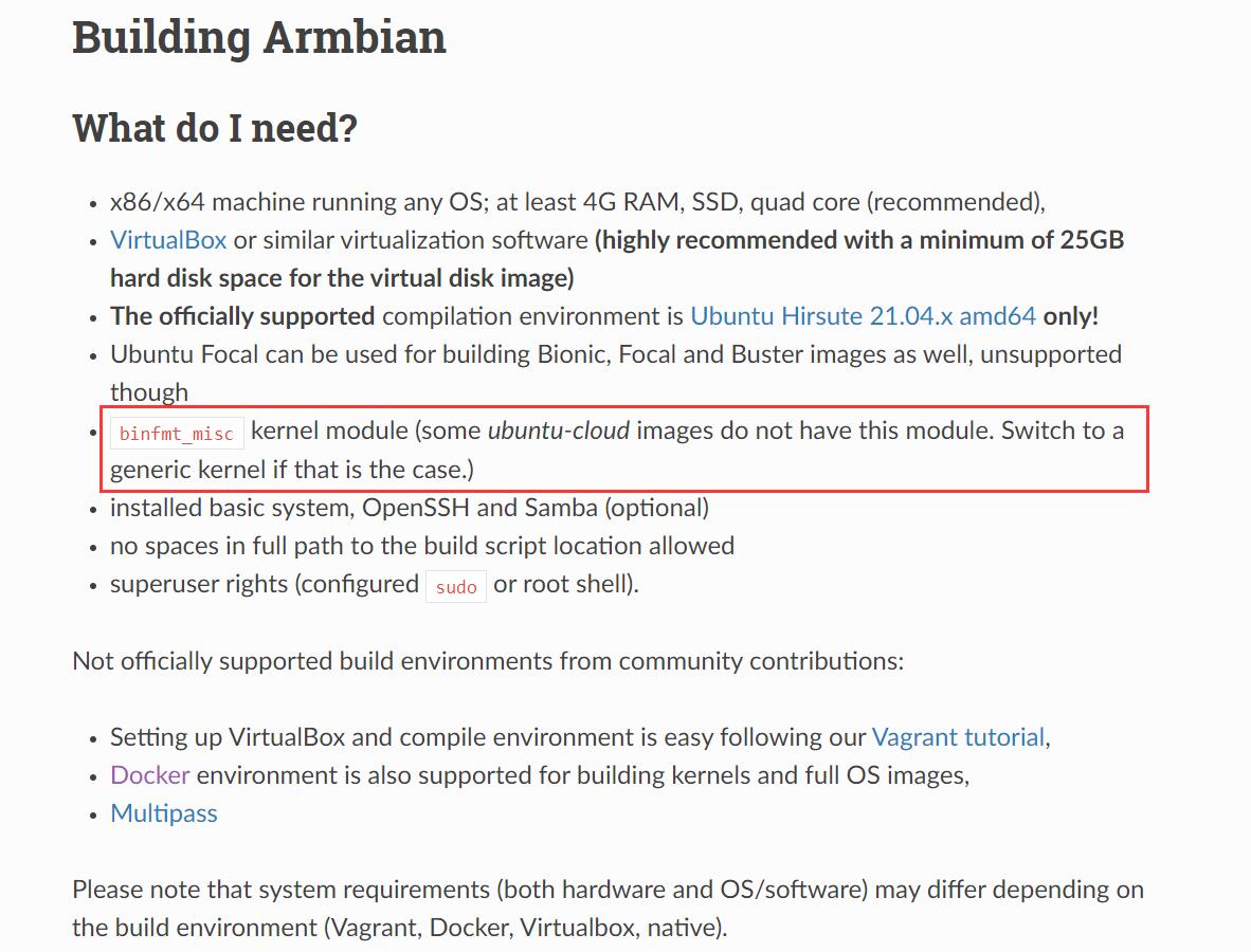
编译报错缺少 binfmt_misc,可是我使用的就是 docker hub 上 ubuntu 官方的镜像,,去哪里找有 binfmt_misc 内核模块的 ubuntu 21.04 docker image 啊?或者怎么安装 binfmt_misc?我试了”apt install binfmt_misc“报错找不到该软件。。
请求各位大佬指点,,谢谢
#177 Re: DIY/综合/Arduino/写字机/3D打印机/智能小车/平衡车/四轴飞行/MQTT/物联网 » 有没有便宜点的带usb 3.0的芯片? » 2021-11-12 10:15:02
#178 Re: DIY/综合/Arduino/写字机/3D打印机/智能小车/平衡车/四轴飞行/MQTT/物联网 » 有没有便宜点的带usb 3.0的芯片? » 2021-11-12 09:24:22
#179 Re: 技术人生/软件使用技巧/破解经验/技术吐槽/灌水 » 坐标深圳,招两个MCU软件工程师 » 2021-11-09 09:35:53
#180 Re: 全志 SOC » 【全开源/D1s】芒果派麻雀 MangoPi-MQ1 基于D1s 的 RISC-V Linux小板 【最新消息:淘宝开卖了,链接在一楼】 » 2021-10-27 16:12:18
#181 Re: RISC-V » 国产riscv芯片汇总 » 2021-10-26 14:17:31
@XIVN1987
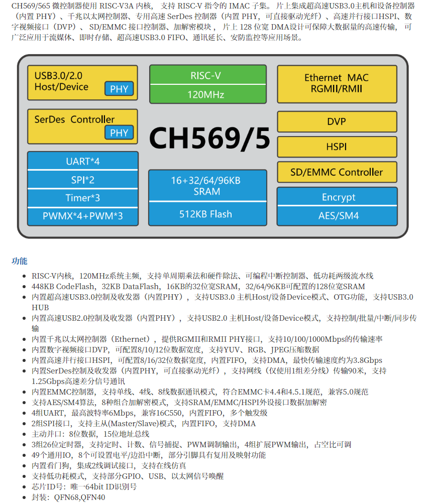
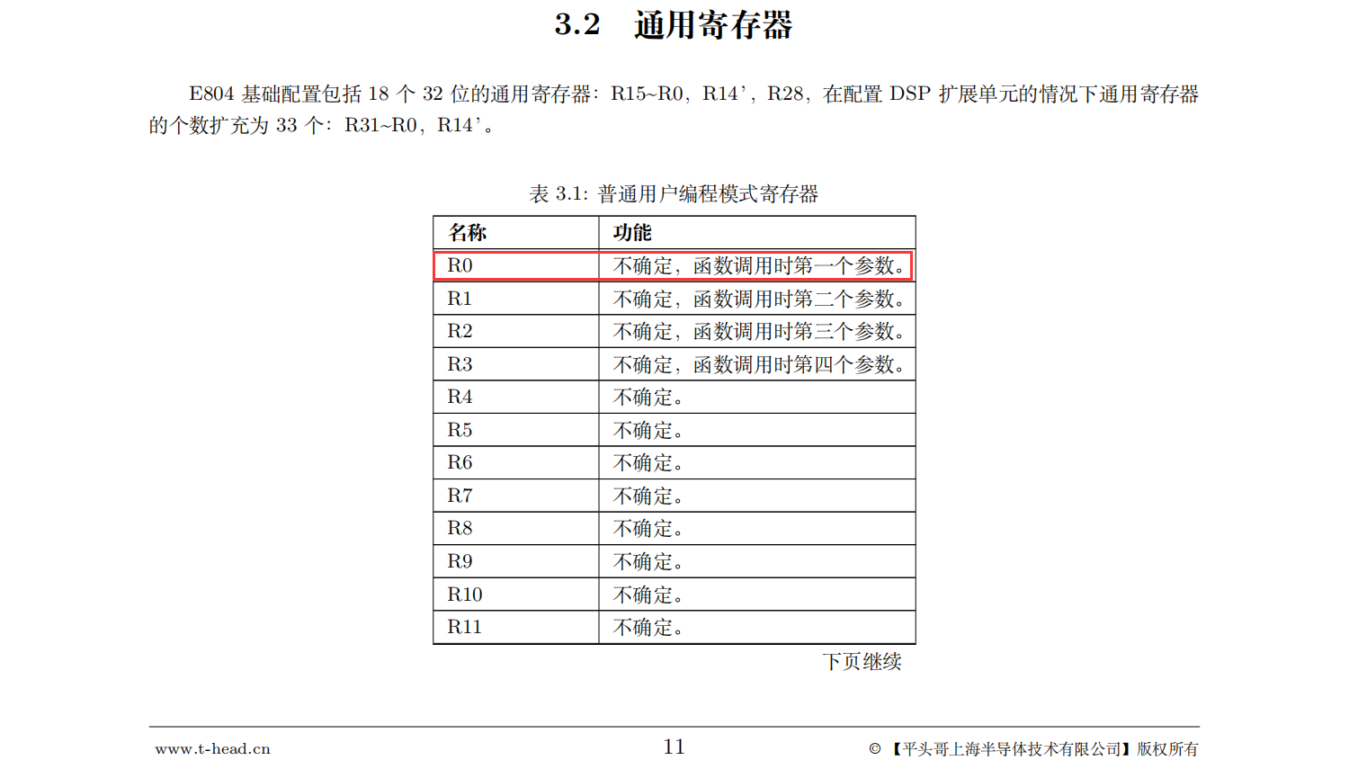
不管是8系列还是9系列都是c-sky指令集,可能版本不同分别对应v2和v3。c-sky基于riscv构建,兼容riscv。这是官方的技术特征里写明的,除非文档有误。
下面是从平头哥官网下载的“玄铁E804”手册,兼容不兼容看手册最靠谱。。
#182 Re: RISC-V » 国产riscv芯片汇总 » 2021-10-26 10:53:39
#183 Re: RISC-V » 国产riscv芯片汇总 » 2021-10-22 23:14:41
#186 RK3288/RK3399/RK1108 » WSL下使用串口助手 » 2021-09-20 19:03:12
- XIVN1987
- 回复: 1
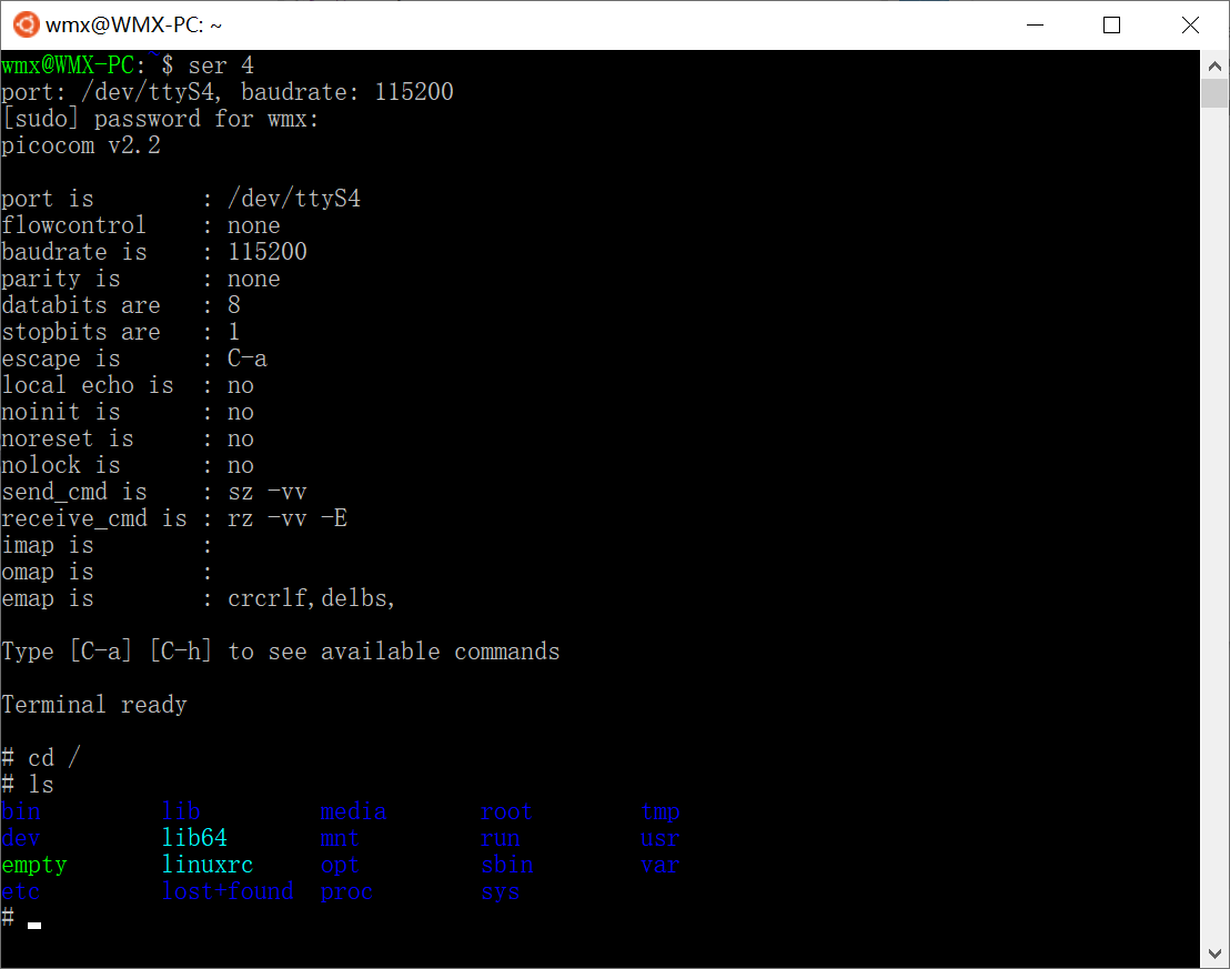
这样串口助手和SSH客户端都能用WSL bash实现了,不在再装putty之类的软件了
function ser {
    if   [ $# -eq 0 ]; then
        return
    elif [ $# -eq 1 ]; then
        port=/dev/ttyS$1
        baudrate=115200
    elif [ $# -eq 2 ]; then
        port=/dev/ttyS$1
        baudrate=$2
    fi

    echo "port: $port, baudrate: $baudrate"

    sudo chmod 666 $port
    sudo stty -F $port $baudrate
    sudo picocom -b $baudrate $port
}
#187 Re: RISC-V » 自制博流bl702精致小板 » 2021-09-17 13:16:03
#188 Re: 技术人生/软件使用技巧/破解经验/技术吐槽/灌水 » 怎么就管不住这买板子的手 » 2021-09-17 13:13:41
#192 Re: ESP32/ESP8266 » 除了ESP32/ESP8266还有其它厂家用Xtensa的核心吗? » 2021-09-16 11:55:02
其实SDK已经把底层都给封装好了,底层什么核心并不重要。
RISC-V只出了ESP32-C3一款而已。
又出了个 ESP32-H2,BLE + Zigbee
https://www.espressif.com/zh-hans/news/ESP32_H2?position=6&list=2Jmgp20Ks2hwxwuzBiWoW-cyTclWAsDkriUiwY4moV4
#193 Re: RK3288/RK3399/RK1108 » dw-apb-uart ff0a0000.serial: set rate:3686400, but get rate:3428572 » 2021-09-02 22:32:53
问题解决了,,解决方法:
将 drivers/tty/serial/8250/8250_dw.c 中函数 dw8250_set_termios() 里面的
#ifdef CONFIG_ARCH_ROCKCHIP
	if ((baud * 16) <= 4000000) {
		/*
		 * Make sure uart sclk is high enough
		 */
		div = 4000000 / baud / 16;
		rate = baud * 16 * div;
	} else {
		rate = baud * 16;
	}

	ret = clk_set_rate(d->clk, rate);
	rate_temp = clk_get_rate(d->clk);
	diff = rate * 20 / 1000;
	/*
	 * If rate_temp is not equal to rate, is means fractional frequency
	 * division is failed. Then use Integer frequency division, and
	 * the buad rate error must be under -+2%
	 */
	if ((rate_temp < rate) && ((rate - rate_temp) > diff)) {
		ret = clk_set_rate(d->clk, rate + diff);
		rate_temp = clk_get_rate(d->clk);
		if ((rate_temp < rate) && ((rate - rate_temp) > diff))
			dev_info(p->dev, "set rate:%d, but get rate:%d\n",
				 rate, rate_temp);
		else if ((rate < rate_temp) && ((rate_temp - rate) > diff))
			dev_info(p->dev, "set rate:%d, but get rate:%d\n",
				 rate, rate_temp);
	}
#else
替换为:
#ifdef CONFIG_ARCH_ROCKCHIP
	rate = clk_get_rate(clk_get_parent(d->clk));
	ret = clk_set_rate(d->clk, rate);
#else#194 Re: SigmaStar/SSD201/SSD202/SSD212 » SSD芯片功能差异表 » 2021-09-02 15:09:00
#196 Re: ESP32/ESP8266 » ESP8266的外设真的很拉垮 » 2021-09-01 15:53:25
#197 RK3288/RK3399/RK1108 » __PHYS_OFFSET == KIMAGE_VADDR ? » 2021-08-17 11:04:44
- XIVN1987
- 回复: 0
// arch/arm64/kernel/head.S
#define __PHYS_OFFSET   (KERNEL_START - TEXT_OFFSET)

// arch/arm64/include/asm/memory.h
#define KERNEL_START      _text

// arch/arm64/kernel/vmlinux.lds.S
    . = KIMAGE_VADDR + TEXT_OFFSET;

    .head.text : {
        _text = .;
        HEAD_TEXT
    }

因此:
__PHYS_OFFSET = (KERNEL_START - TEXT_OFFSET)
              = (_text - TEXT_OFFSET)
              = (KIMAGE_VADDR + TEXT_OFFSET - TEXT_OFFSET)
              = KIMAGE_VADDR
这两个符号一个叫“物理偏移”,一个叫“虚拟地址”,,最终却是同一个取值??
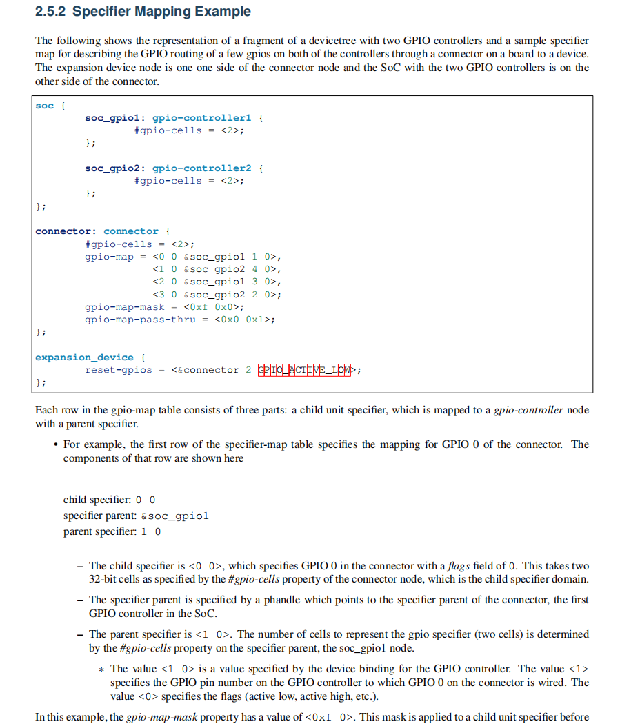
#198 Re: RK3288/RK3399/RK1108 » Devicetree Spec 上的 Specifier Mapping Example 什么意思?看迷糊了,哪位大神给讲讲。。 » 2021-08-14 07:45:01
又读了几遍,,感觉意思是:
expansion_device 的 reset 使用的 GPIO 是“<&soc_gpio1 3 GPIO_ACTIVE_LOW>”,推导如下:
1、查表前先执行 mask,<2 GPIO_ACTIVE_LOW> & <0xf 0x0> 得 <0x2 0>
2、使用<0x2 0>查表,查得 specifier parent 为 &soc_gpio1,parent specifier 为 <3 0>
3、pass-thru 为 <0x0 0x1>,因此 <2 GPIO_ACTIVE_LOW> 的第二个 cell 的最低位需要无修改地从 child node 传递给 parent node,即 parent node 的第二个 cell变为 GPIO_ACTIVE_LOW
#199 RK3288/RK3399/RK1108 » Devicetree Spec 上的 Specifier Mapping Example 什么意思?看迷糊了,哪位大神给讲讲。。 » 2021-08-13 18:22:42
- 首页
- » 搜索
- » XIVN1987 发表的帖子
太原小智科技有限责任公司 - 东莞哇酷科技有限公司联合开发

