#1 Re: 全志 SOC » F1C200S新老版本有什么区别? » 2026-06-28 10:00:26
#2 Re: 全志 SOC » 做了一批V821的板子,现在招募有识之士一起调试开发 » 2025-11-05 08:29:58
#3 Re: 全志 SOC » 做了一批V821的板子,现在招募有识之士一起调试开发 » 2025-11-05 08:22:31
#5 Re: 全志 SOC » 昆仑的屏运行自己的QT程序 » 2025-08-26 16:44:30
#8 Re: 感芯科技 » 老电脑装Linux能恢复青春吗? » 2025-01-21 21:14:35
#10 Re: RISC-V » CH32V003上使用多任务FORTH » 2024-09-26 20:47:48
我没用openocd,找到了个minilink软件也能debug,不过有些bug,单步不太好用。
https://github.com/cnlohr/ch32v003fun
这个项目不错,有minilink的使用方法。
https://github.com/cnlohr/rv003usb
汇编实现了usb协议栈
#11 Re: RISC-V » CH32V003上使用多任务FORTH » 2024-09-21 08:22:49
#12 Re: 全志 SOC » musb编程指南中文版 » 2024-06-01 08:58:58
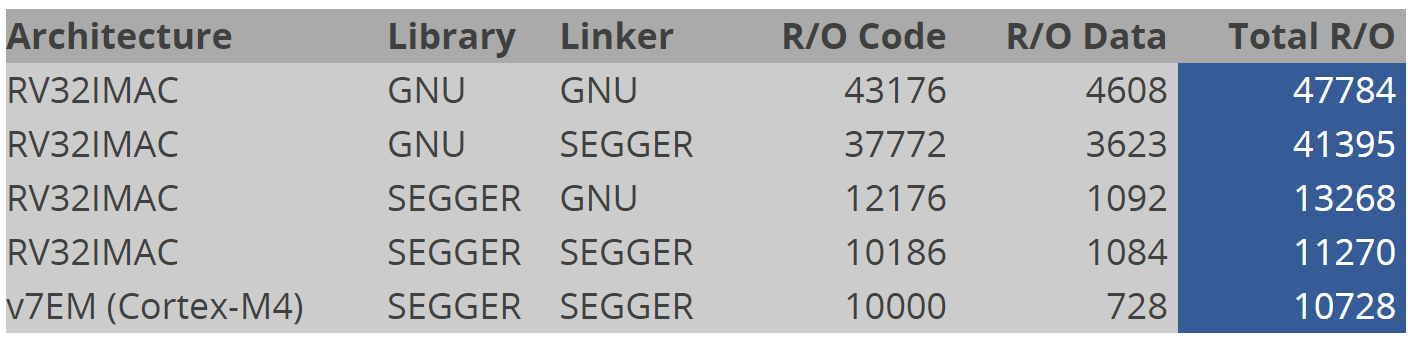
#13 Re: RISC-V » RISC-V代码密度相比Cortex-M差距明显 » 2024-05-18 13:15:10
#14 Re: 全志 SOC » T113-S3 开源双核 FunKey 掌机硬件和系统 » 2024-04-26 08:45:24
#15 Re: 工业芯 匠芯创 » 有没有好用迷你的程序和gui工具推荐? » 2024-04-22 22:26:24
#18 Re: 司徒开源 » RK3588 开源掌机 16+256 » 2024-03-09 10:06:04
#19 Re: 全志 SOC » f1c100s/200s图形化烧录工具 » 2024-01-19 13:45:55
gosunxifel.zip
关于闪退问题,将exe文件替换成这个,应该就可以了
#20 Re: 全志 SOC » f1c100s/200s图形化烧录工具 » 2024-01-19 12:50:46
#21 RISC-V » 关于ch32v003链接脚本的问题 » 2023-10-27 14:51:57
- kekemuyu
- 回复: 1
下面的连接脚本,有很多段不是很明白,有大佬能解释一下吗?比如.fini_array ,.ctors, .dtors
ENTRY( jump_reset )

MEMORY
{
  FLASH (rx) : ORIGIN = 0x00000000, LENGTH = 16K
  RAM (xrw)  : ORIGIN = 0x20000000, LENGTH = 2K
}

SECTIONS
{
  .init :
  {
    _sinit = .;
    . = ALIGN(4);
    KEEP(*(SORT_NONE(.init.jump)))
    KEEP(*(SORT_NONE(.init.vectors)))
    . = ALIGN(4);
    _einit = .;
  } >FLASH AT>FLASH

  .text :
  {
    . = ALIGN(4);
    *(.text)
    *(.text.*)
    *(.rodata)
    *(.rodata*)
    *(.gnu.linkonce.t.*)
    . = ALIGN(4);
  } >FLASH AT>FLASH

  .fini :
  {
    KEEP(*(SORT_NONE(.fini)))
    . = ALIGN(4);
  } >FLASH AT>FLASH

  PROVIDE( _etext = . );
  PROVIDE( _eitcm = . );

  .preinit_array :
  {
    PROVIDE_HIDDEN(__preinit_array_start = .);
    KEEP(*(.preinit_array))
    PROVIDE_HIDDEN(__preinit_array_end = .);
  } >FLASH AT>FLASH

  .init_array :
  {
    PROVIDE_HIDDEN(__init_array_start = .);
    KEEP(*(SORT_BY_INIT_PRIORITY(.init_array.*) SORT_BY_INIT_PRIORITY(.ctors.*)))
    KEEP(*(.init_array EXCLUDE_FILE (*crtbegin.o *crtbegin?.o *crtend.o *crtend?.o ) .ctors))
    PROVIDE_HIDDEN(__init_array_end = .);
  } >FLASH AT>FLASH

  .fini_array :
  {
    PROVIDE_HIDDEN(__fini_array_start = .);
    KEEP(*(SORT_BY_INIT_PRIORITY(.fini_array.*) SORT_BY_INIT_PRIORITY(.dtors.*)))
    KEEP(*(.fini_array EXCLUDE_FILE (*crtbegin.o *crtbegin?.o *crtend.o *crtend?.o ) .dtors))
    PROVIDE_HIDDEN(__fini_array_end = .);
  } >FLASH AT>FLASH

  .ctors :
  {
    KEEP(*crtbegin.o(.ctors))
    KEEP(*crtbegin?.o(.ctors))
    KEEP(*(EXCLUDE_FILE (*crtend.o *crtend?.o ) .ctors))
    KEEP(*(SORT(.ctors.*)))
    KEEP(*(.ctors))
  } >FLASH AT>FLASH

  .dtors :
  {
    KEEP(*crtbegin.o(.dtors))
    KEEP(*crtbegin?.o(.dtors))
    KEEP(*(EXCLUDE_FILE (*crtend.o *crtend?.o ) .dtors))
    KEEP(*(SORT(.dtors.*)))
    KEEP(*(.dtors))
  } >FLASH AT>FLASH

  .dalign :
  {
    . = ALIGN(4);
    PROVIDE(_data_vma = .);
  } >RAM AT>FLASH

  .dlalign :
  {
    . = ALIGN(4);
    PROVIDE(_data_lma = .);
  } >FLASH AT>FLASH

  .data :
  {
    . = ALIGN(4);
    *(.gnu.linkonce.r.*)
    *(.data .data.*)
    *(.gnu.linkonce.d.*)
    . = ALIGN(8);
    PROVIDE( __global_pointer$ = . + 0x800 );
    *(.sdata .sdata.*)
    *(.sdata2*)
    *(.gnu.linkonce.s.*)
    . = ALIGN(8);
    *(.srodata.cst16)
    *(.srodata.cst8)
    *(.srodata.cst4)
    *(.srodata.cst2)
    *(.srodata .srodata.*)
    . = ALIGN(4);
    PROVIDE( _edata = .);
  } >RAM AT>FLASH

  .bss :
  {
    . = ALIGN(4);
    PROVIDE( _sbss = .);
    *(.sbss*)
    *(.gnu.linkonce.sb.*)
    *(.bss*)
    *(.gnu.linkonce.b.*)
    *(COMMON*)
    . = ALIGN(4);
    PROVIDE( _ebss = .);
  } >RAM AT>FLASH

  PROVIDE( _end = _ebss);
  PROVIDE( end = . );
  PROVIDE( _eusrstack = ORIGIN(RAM) + LENGTH(RAM));
}#23 Re: 技术人生/软件使用技巧/破解经验/技术吐槽/灌水 » bl808资料汇总 » 2023-07-20 18:46:52
#24 Re: 全志 SOC » 全志 A523 八核A55 超越RK3568 » 2023-07-20 18:37:19
#25 Re: 全志 SOC » CoreMark Benchmark » 2023-06-15 07:35:09
#26 Re: RISC-V » MilkV duo 有人玩吗? » 2023-05-26 09:12:35
#27 Re: 全志 SOC » 全志R128来袭,有想入坑的吗?我先来点初步研究成果 » 2023-05-17 08:44:42
#28 Re: Cortex M0/M3/M4/M7 » 国产M7来了,分享datasheet » 2023-05-12 08:40:42
#32 Re: DIY/综合/Arduino/写字机/3D打印机/智能小车/平衡车/四轴飞行/MQTT/物联网 » 【新玩具get】AGM AGRV2K,16.8块钱的MCU+FPGA二合一芯片 » 2023-03-16 13:15:43
#35 技术人生/软件使用技巧/破解经验/技术吐槽/灌水 » 屌炸天的技术(cpu偷梁换柱) » 2023-03-11 10:43:01
- kekemuyu
- 回复: 11
首先介绍一下背景:以下是plan9的故事
例一、替换 CPU
假想一下我们有一台日常使用但性能不佳的笔记本,和一台不在本地但性能强劲的服务器。 我们当然能够使用远程计算机的强劲的 CPU 运行一些计算量特大的程序。这不是什么难事,因为几乎所有操作系统都支持登陆到远程的机器。然而,麻烦的是,如果在远程运行程序需要读写本地的文件,或者访问挂载在本地笔记本上的打印机,扬声器麦克风之类设备,我们除了在本地和远程之间把文件传来传去之外,并没有什么好方法。特别的,如果我们想借用另一台计算机上强劲的 CPU 做音频和视频解码,来播放一个放在本机光盘驱动器里的电影文件的话,我们是不可能指望远程计算机既能读本地的光驱,又能把音频投递到本机的扬声器上的。
Plan 9 中,有一个简单的 cpu 命令,能够让用户自然地使用一个其他机器上的 CPU 运行程序,且仍然能够访问本地的所有文件和设备。也就是说,我们可以用远程计算机上强劲的 CPU 做图像处理,媒体解码等任务,并且可以直接把声音播放到本地的扬声器。cpu 命令给人的感觉,是除了给机器换个了 cpu 外,其他一切都和原来一样。这个看似 “神奇” 的功能,其实在 Plan 9 里实现起来一点都不复杂: cpu 指令首先连接服务器上,然后将本地的所有资源和文件系统,包括窗口管理器,光盘驱动器,扬声器等设备(别忘了他们都是文件),一股脑儿挂载到服务器上,成为服务器上的资源。这样,在服务器上运行的程序,就可以“自然地”使用本地的键盘鼠标和显示器完成交互,还可以访问你本地的显示器扬声器等设备。
cpu 命令真的就是名副其实的换掉了本地计算机的 cpu (其实还有内存)而保留其他一切设备。Plan 9 的这个 cpu 命令,带有强烈的分布式操作系统的特征,而我们平时接触的操作系统都不是分布式操作系统,因此 cpu 这个命令至今在现代主流操作系统上没有完全等价物。
现在这个牛逼的cpu命令移植到了linux系统,它是完全用go实现的。
请看以下简介:
The u-root cpu command
Do you want to have all the tools on your linuxboot system that you have on your desktop, but you can’t get them to fit in your tiny flash part? Do you want all your desktop files visible on your linuxboot system, but just remembered there’s no disk on your linuxboot system? Are you tired of using scp or wget to move files around? Do you want to run emacs or vim on the linuxboot machine, but know they can’t ever fit? What about zsh? How about being able to run commands on your linuxboot machine and have the output appear on your home file system? You say you’d like to make this all work without having to fill out web forms in triplicate to get your organization to Do Magic to your desktop?
Your search is over: cpu is here to answer all your usability needs.
The problem: running your program on some other system
People often need to run a command on a remote system. That is easy when the remote system is the same as the system you are on, e.g., both systems are Ubuntu 16.04; and all the libraries, packages, and files are roughly the same. But what if the systems are different, say, Ubuntu 16.04 and Ubuntu 18.10? What if one is Centos, the other Debian? What if a required package is missing on the remote system, even though in all other ways they are the same?
While these systems are both Linux, and hence can provide Application Binary Interface (ABI) stability at the system call boundary, above that boundary stability vanishes. Even small variations between Ubuntu versions matter: symbol versions in C libraries differ, files are moved, and so on.
What is a user to do if they want to build a binary on one system, and run it on another system?
The simplest approach is to copy the source to that other system and compile it. That works sometimes. But there are limits: copying the source might not be allowed; the code might not even compile on the remote system; some support code might not be available, as for a library; and for embedded systems, there might not be a compiler on the remote system. Copy and compile is not always an option. In fact it rarely works nowadays, when even different Linux distributions are incompatible.
The next option is to use static linking. Static linking is the oldest form of binary on Linux systems. While it has the downside of creating larger binaries, in an age of efficient compilers that remove dead code, 100 gigabit networks, and giant disks and memory, that penalty is not the problem it once was. The growth in size of static binaries is nothing like the growth in efficiency and scale of our resources. Nevertheless, static linking is frowned upon nowadays and many libraries are only made available for dynamic linking.
Our user might use one of the many tools that package a binary and all its libraries into a single file, to be executed elsewhere. The u-root project even offers one such tool, called pox, for portable executables. Pox uses the dynamic loader to figure out all the shared libraries a program uses, and place them into the archive as well. Further, the user can specify additional files to carry along in case they are needed.
The problem here is that, if our user cares about binary size, this option is even worse. Deadcode removal won’t work; the whole shared library has to be carried along. Nevertheless, this can work, in some cases.
So our user packages up their executable using pox or a similar tool, uses scp to get it to the remote machine, logs in via ssh, and all seems to be well, until at some point there is another message about a missing shared library! How can this be? The program that packaged it up checked for all possible shared libraries.
Unfortunately, shared libraries are now in the habit of loading other shared libraries, as determined by reading text files. It’s no longer possible to know what shared libraries are used; they can even change from one run of the program to the next. One can not find them all just by reading the shared library itself. A good example is the name service switch library, which uses /etc/nsswitch.conf to find other shared libraries. If nsswitch.conf is missing, or a library is missing, some versions of the name service switch library will core dump.
Not only must our user remember to bring along /etc/nsswitch.conf, they must also remember to bring along all the libraries it might use. This is also true of other services such as Pluggable Authentication Modules (PAM). And, further, the program they bring along might run other programs, with their own dependencies. At some point, as the set of files grows, frustrated users might decide to gather up all of /etc/, /bin, and other directories, in the hope that a wide enough net might bring along all that’s needed. The remote system will need lots of spare disk or memory! We’re right back where we started, with too many files for too little space.
In the worst case, to properly run a binary from one system, on another system, one must copy everything in the local file system to the remote system. That is obviously difficult, and might be impossible if the remote system has no disk, only memory.
One might propose having the remote system mount the local system via NFS or Samba. While this was a common approach years ago, it comes with its own set of problems: all the remote systems are now hostage to the reliability of the NFS or Samba server. But there’s a bigger problem: there is still no guarantee that the remote system is using the same library versions and files that the user’s desktop is using. The NFS server might provide, e.g., Suse, to the remote system; the user’s desktop might be running Ubuntu. If the user compiles on their desktop, the binary might still not run on the remote system, as the Suse libraries might be different. This is a common problem.
Still worse, with an NFS root, everyone can see everyone’s files. It’s like living in an apartment building with glass walls. Glass houses only look good in architecture magazines. People want privacy.
https://github.com/u-root/cpu
https://book.linuxboot.org/cpu/
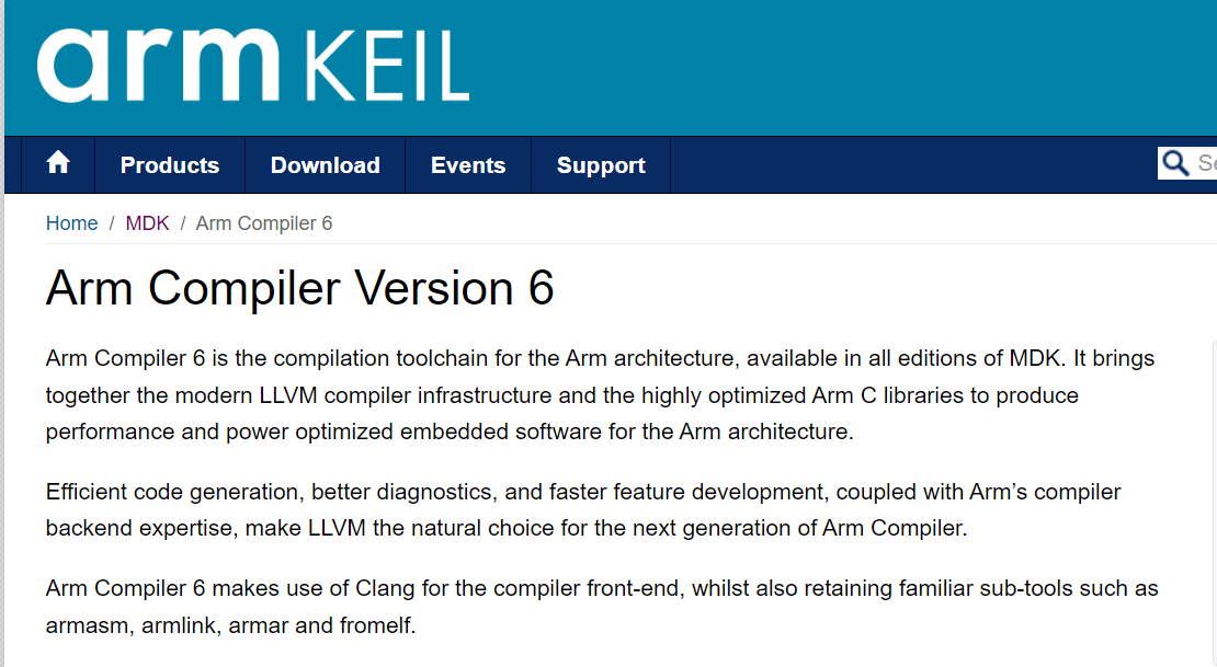
#36 Re: RISC-V » 为什么mcu厂家还是用gcc而不是llvm » 2023-03-11 09:17:08
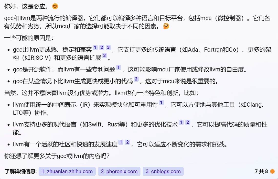
#37 Re: RISC-V » 为什么mcu厂家还是用gcc而不是llvm » 2023-03-10 14:13:43
keil的也换成LLVM了,https://www2.keil.com/mdk5/compiler/6/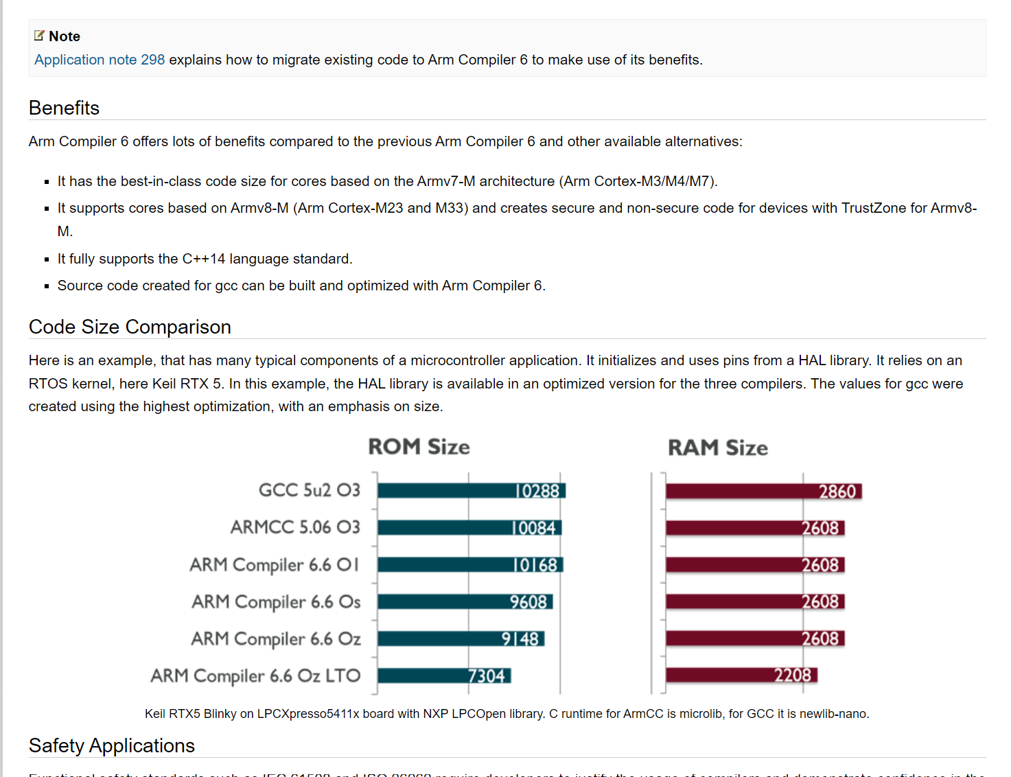
#39 Re: ESP32/ESP8266 » 乐鑫要发的新芯片esp32-P4 » 2023-01-07 20:25:24

#40 Re: ESP32/ESP8266 » 乐鑫要发的新芯片esp32-P4 » 2023-01-06 12:16:59
#41 Re: ESP32/ESP8266 » 乐鑫要发的新芯片esp32-P4 » 2023-01-06 12:15:34
#42 Re: 全志 SOC » 平头哥云上实验室,可以申请远程测试大量芯片或开发板 » 2023-01-05 19:53:23
#43 Re: RISC-V » RISC-V不支持非对齐地址访问非常坑 » 2023-01-05 19:51:45
#44 Re: 全志 SOC » F1C100S/F1C200S如何进入休眠模式 » 2023-01-05 09:00:15
#47 DIY/综合/Arduino/写字机/3D打印机/智能小车/平衡车/四轴飞行/MQTT/物联网 » 杰里芯片官网开始拥抱社区了吗 » 2023-01-04 00:12:01
- kekemuyu
- 回复: 13
看到一份官网开发文档https://doc.zh-jieli.com/AC79/zh-cn/master/index.html,然后在淘宝和b站都有看到官方在普及芯片。芯片性价比真是无敌呀
#48 Re: RISC-V » 博流智能将要推出杀手级芯片bl808(可以跑linux) » 2023-01-03 15:12:15
#49 Re: 上海航芯 » ACM32H5新产品需求及意见收集 » 2022-12-17 21:32:01
#52 Re: RISC-V » 博流智能将要推出杀手级芯片bl808(可以跑linux) » 2022-11-02 22:25:02
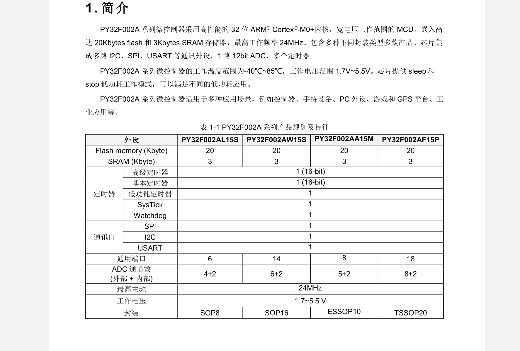
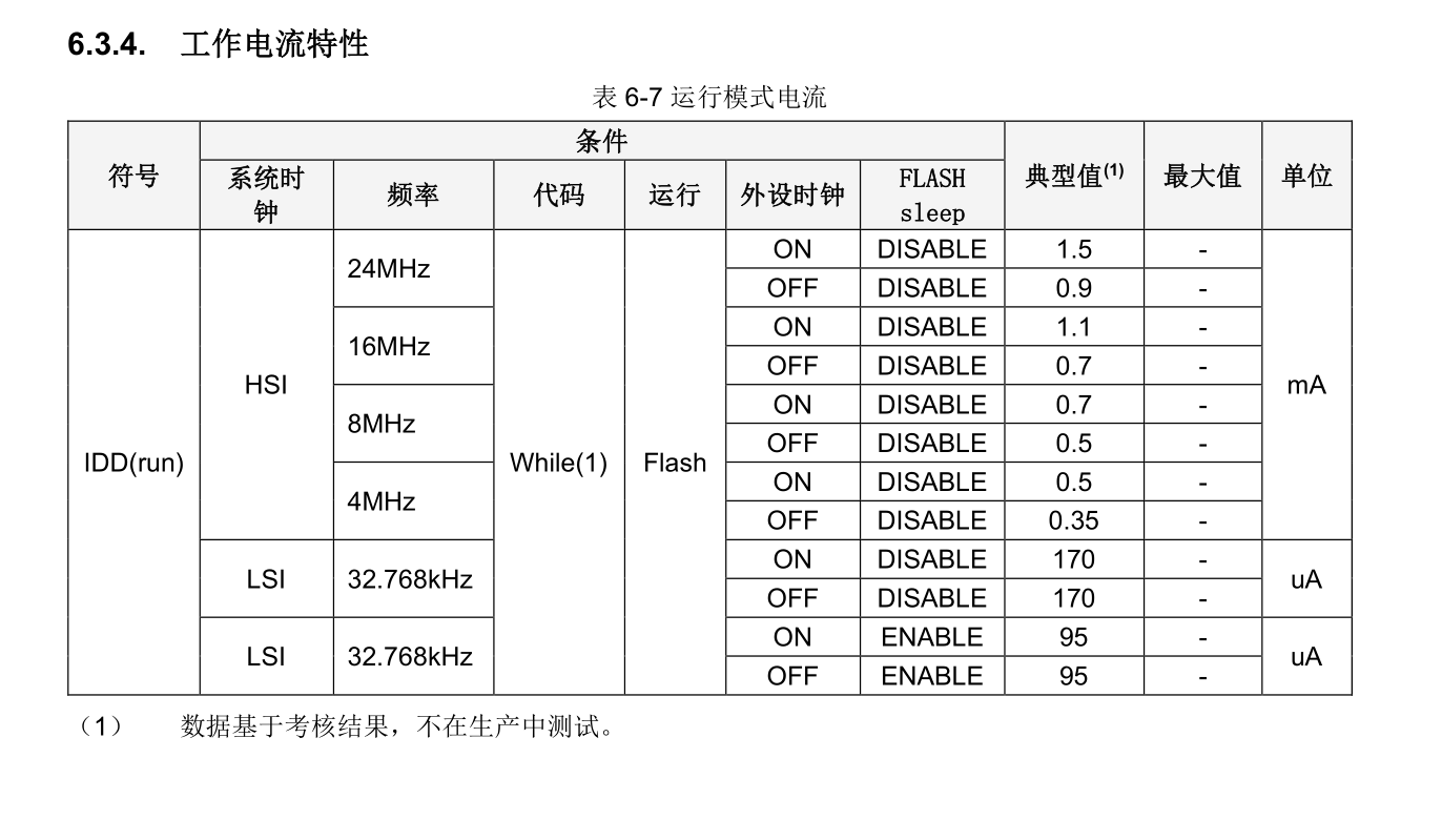
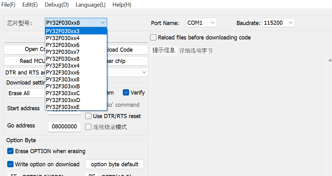
#56 Re: Cortex M0/M3/M4/M7 » 国产王炸中的战斗机-普冉py32f003/py32f030(价格6毛起步) » 2022-10-31 22:29:48
@echo
关于py32f003的isp烧录,我在网上找到了个方法,还没实际操作过不知道行不行。主要是这句话:上电1s内默认是isp编程模式。
https://blog.csdn.net/firseve/article/details/126661827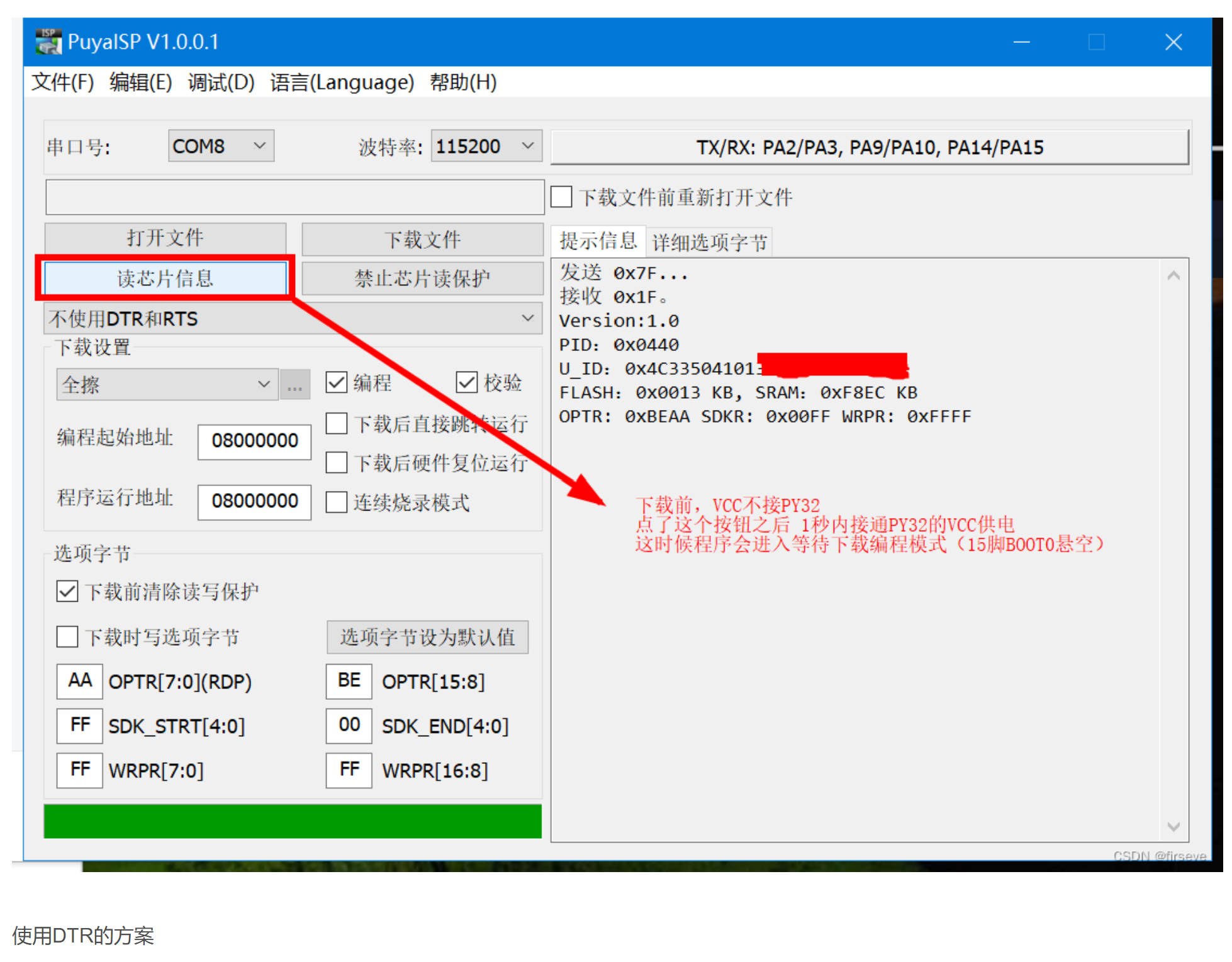
#58 Re: RISC-V » 博流智能将要推出杀手级芯片bl808(可以跑linux) » 2022-10-27 22:14:07
#59 Re: RISC-V » 博流智能将要推出杀手级芯片bl808(可以跑linux) » 2022-10-27 22:06:59
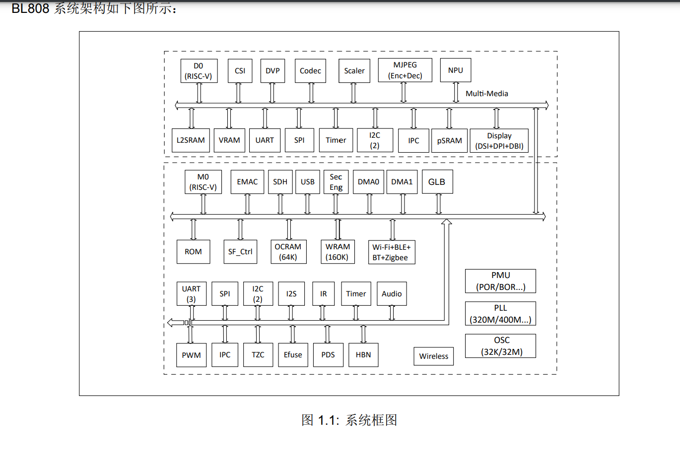
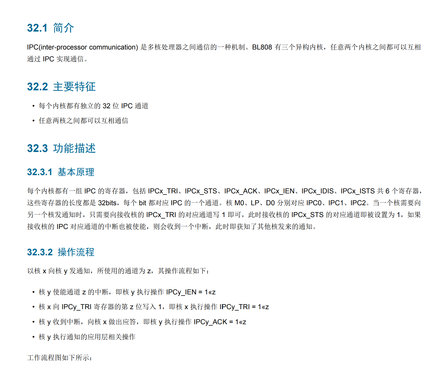
BL808_RM_zhBL808_RM_zh.pdf
BL808_DS_zhBL808_DS_zh.pdf
#60 RISC-V » 博流智能将要推出杀手级芯片bl808(可以跑linux) » 2022-10-27 19:58:28
- kekemuyu
- 回复: 42
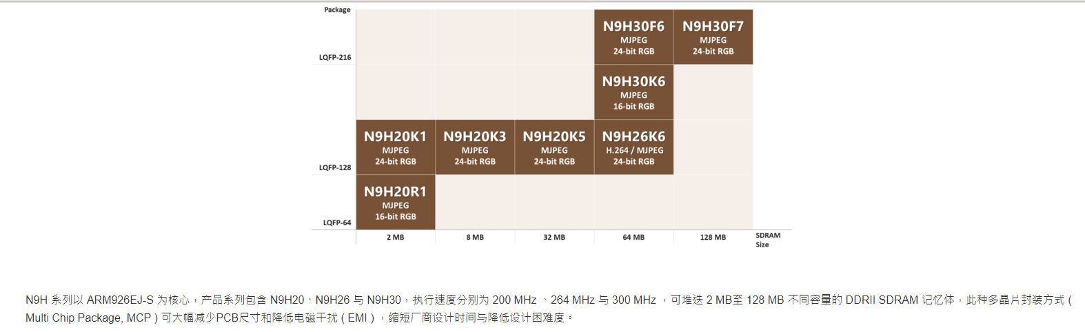
这价格如果在10元左右,f1c100s可以退休了
https://www.cnx-software.com/2022/10/10/pine64-ox64-sbc-bl808-risc-v-multi-protocol-wisoc-64mb-ram/
SoC – Bouffalo Lab BL808 with:
CPU
Alibaba T-head C906 64-bit RISC-V core @ 480MHz
Alibaba T-head E907 32-bit RISC-V core @ 320MHz
Memory – 64MB embedded DRAM
AI accelerator – NPU BLAI-100 (Bouffalo Lab AI engine) for video/audio detection/recognition
Wireless
2.4 GHz 802.11 b/g/n Wi-Fi 4
Bluetooth 5.x dual mode (classic + BLE)
IEEE 802.15.4 for Zigbee
Display
Up to 4-lane MIPI DSI
Up to 8-bit MIPI DBI
16-bit MIPI DPI
QSPI
Audio Codec – 2x ADC, 1x DAC, sample rate: 8 to 192KHz, 24-bit
Camera
2-lane MIPI CSI and DVP interfaces
MJPEG and H.264 encoder up to 1920×1080 @ 30fps + 640×480 @ 30fps
Package – 88-pin QFN
Storage
16Mbit (2MB) or 128Mbit (16MB) XSPI NOR flash
MicroSD socket with support for SDHC and SDXC
Camera & audio – 2-lane MIPI CSI co-located with USB-C port for camera module including microphone and speaker
Antenna – 2.4GHz chip antenna soldered on board, footprint for u.FL connector
USB – 1x USB 2.0 OTG Type-C port with MIPI CSI “alternative” mode
Expansion – 2x 20-pin headers with castellated holes with GPIO, SPI, I2C, and UART, possible I2S and GMII expansion
Debugging – 5-pin JTAG header
Misc – BOOT button, red power LED
Power Supply – 5V/0.5A via USB Type-C port or micro USB port
Dimensions – 51 x 21 x 19mm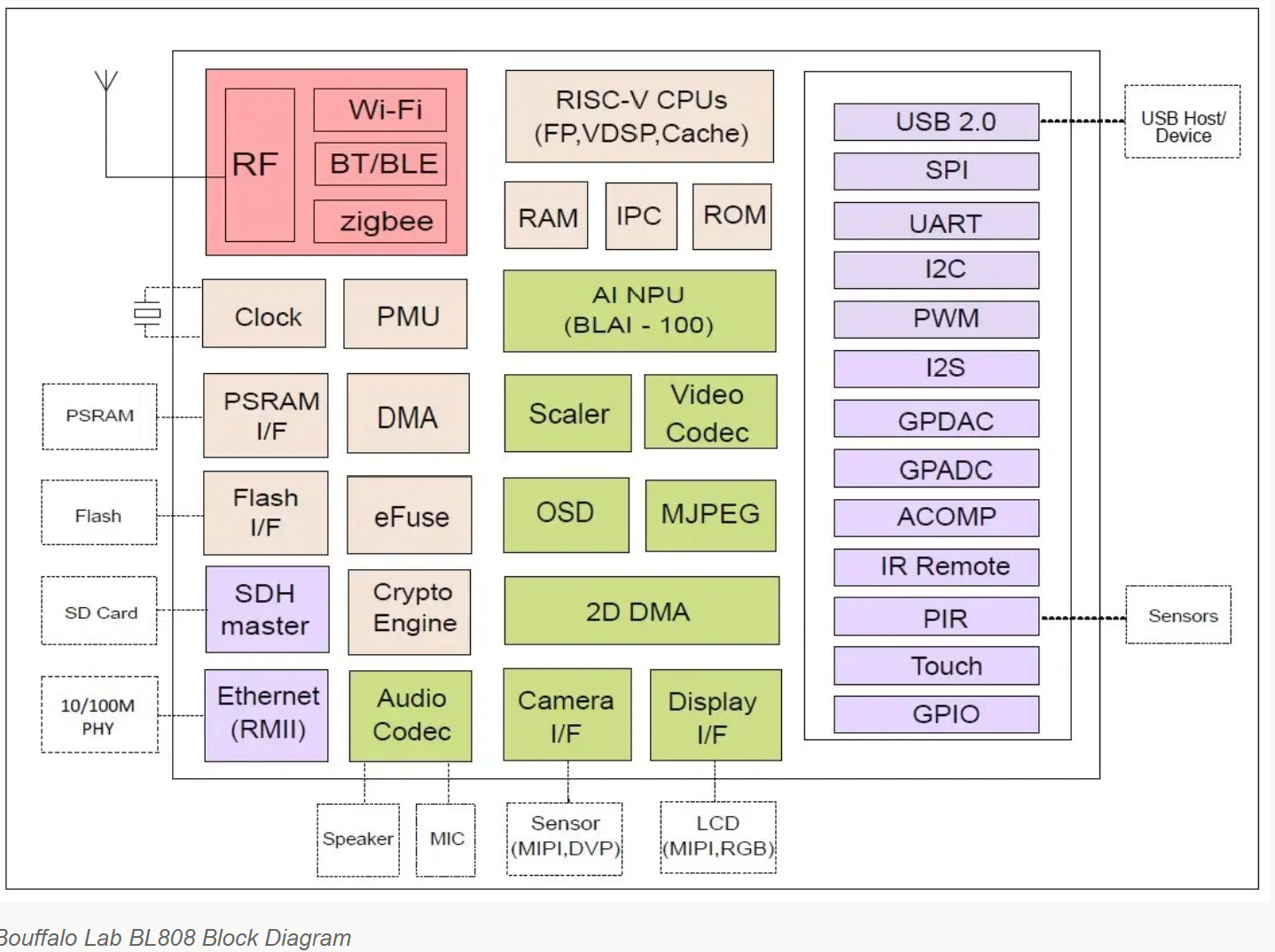
#64 Re: RISC-V » WCH又搞了个性价比王炸CH32V003 » 2022-10-15 15:31:19
#65 Re: RISC-V » WCH又搞了个性价比王炸CH32V003 » 2022-10-13 16:23:43

#67 Re: RISC-V » WCH又搞了个性价比王炸CH32V003 » 2022-10-13 15:55:00
#69 Re: 全志 SOC » 开源一个F1C200S的实用向板,极限压榨这片子的功能 » 2022-08-08 17:08:32
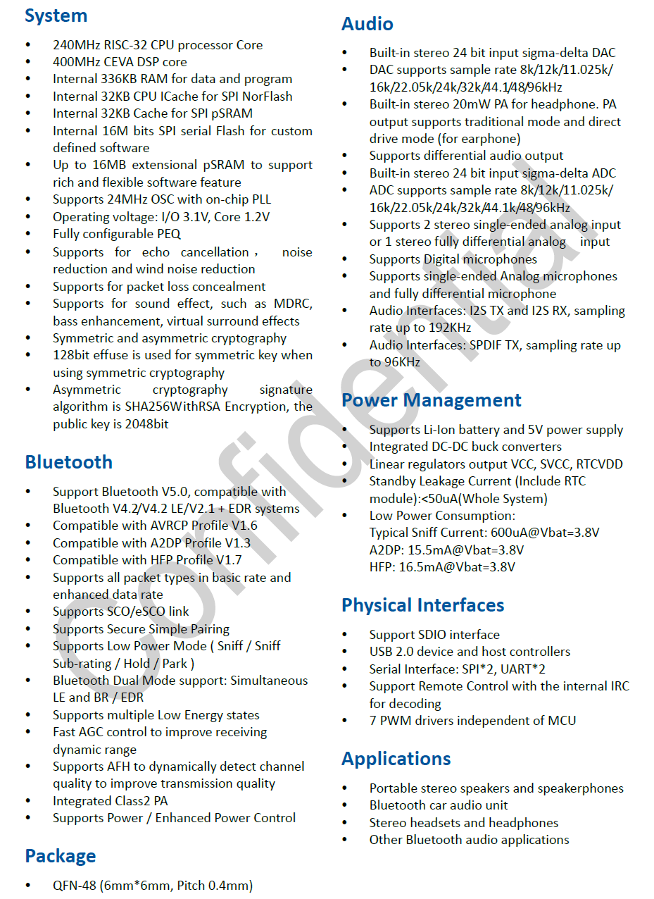
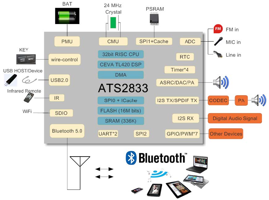
#71 Re: RISC-V » 看到rode无线麦克的拆解用到的芯片是炬芯ats2833 » 2022-07-23 21:52:58
#73 Re: 全志 SOC » 求助,Planck Pi(F1C200S)上电后无反应 » 2022-06-22 22:26:01
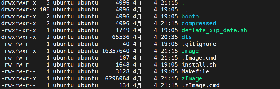
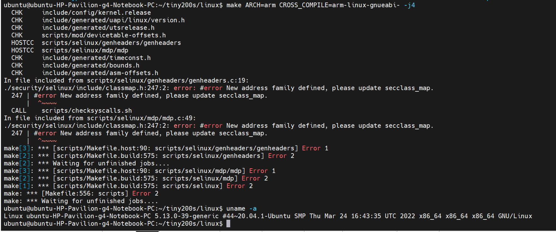
跟着https://blog.csdn.net/qq_41253675/article/details/124898690操作,在tiny200s上把系统跑起来了
#74 Re: 全志 SOC » 成功在f1c100s上运行debian系统 » 2022-06-15 09:17:36
@Jeason1997
https://whycan.com/t_4149.html
#78 Re: 全志 SOC » 分享一个自己试着写的裸机BootLoader,和编写过程中的大坑 » 2022-05-23 10:32:47
有个地方不太理解:
__image_file_start = .;

    .text : AT(__image_file_start)       //就是这里,表示代码链接到DDR内,但编译时存放在文
这里有几个地址没有想明白,依我看启动过程是:brom程序从spi flash拷贝固定大小(不记得是多大了)的二进制文件到sram中,cpu开始从sram的0地址执行指令,指令中有个拷贝代码的程序如下:
/* 加载程序 */
void Boot_Load_Code(void)
{
    Boot_SPI0_Init();
    Boot_SPI_Flash_Read((unsigned int)&__image_file_start, &__image_start, &__image_end - &__image_start);
    Boot_SPI0_Exit();
}
__image_file_start是spi flash的存放位置,二进制程序被拷贝到ddr的地址起始位置,然后cpu跳转到ddr开始执行。
我所不理解的是__image_file_start如果是二进制文件在spi flash的存储位置,那__image_start应该是ddr的开始位置
    .text : AT(__image_file_start)
    {
        PROVIDE(__image_start = .);
        Obj/start.o (.text)
        Obj/main.o (.text)
        *(.text)
		*(.note.gnu.build-id)
    } > ddr
那__image_start的地址具体是多少呢?为何不把二进制程序拷贝到ddr的起始位置呢?由于对链接脚本不太熟,决定做实验验证:先直接修改链接脚本,把__image_start 的地址直接修改成0x80000000
#79 Re: 全志 SOC » 初玩全志 T113-S3, 原来1GHz是极限.... » 2022-05-16 13:55:09
#80 Re: 全志 SOC » 初玩全志 T113-S3, 原来1GHz是极限.... » 2022-05-16 10:31:14
#81 Re: 全志 SOC » go语言裸机编程探索 » 2022-04-09 12:01:07
go语言裸机最小生成elf工程:
add_20220409-1201.zip
#83 Re: 全志 SOC » 尝试从零构建F1C100s开发环境 » 2022-04-04 21:39:11
#84 Re: 全志 SOC » 尝试从零构建F1C100s开发环境 » 2022-04-04 20:04:35
#85 Re: 全志 SOC » 尝试从零构建F1C100s开发环境 » 2022-04-04 19:57:51
#86 Re: 全志 SOC » go语言裸机编程探索 » 2022-03-22 10:39:37
#87 Re: 全志 SOC » go语言裸机编程探索 » 2022-03-21 22:29:34
#88 Re: 全志 SOC » go语言裸机编程探索 » 2022-03-21 15:05:11
另外还可以参考https://git.sr.ht/~eliasnaur/unik/tree,eggos作者就是受这个项目启发做的。两者原理是一样的
#89 Re: 全志 SOC » go语言裸机编程探索 » 2022-03-21 15:01:30
#90 Re: 全志 SOC » go语言裸机编程探索 » 2022-03-21 13:49:02
@xboot
同感,tinygo等于发明了另一种语言,还是跟随官方go比较好。TamaGo就是增加GOARCH GOOS的方案。但是我更倾向eggos的方案,不用修改官方编译器,他是模拟了linux的中断和系统调用。具体原理请参考这篇博文:https://zhuanlan.zhihu.com/p/265806072
#91 全志 SOC » go语言裸机编程探索 » 2022-03-17 10:22:51
- kekemuyu
- 回复: 25
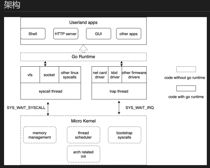
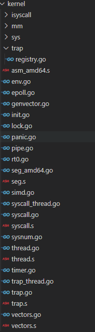
go和c现在是我工作中的主力语言。go在很多领域发挥了强大作用,那go适合嵌入式吗?当前并不适合,但go具有控制硬件的能力,虽然有些繁琐。
本帖最终目的是在全志f1c100s/200s或者说是arm9系列芯片直接运行go程序,主要是把go runtime移植到arm9上。本帖主要是受github的开源项目https://github.com/icexin/eggos的启发,此项目已成功将go runtime移植到x86上。开篇先建立环境:
虚拟环境是qemu-system-arm
先在上面跑个gnu汇编热热身。
arm.zip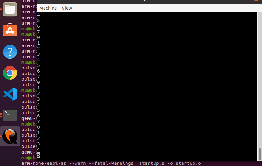
#97 Re: ESP32/ESP8266 » 突发奇想ESP32能不能弄一个微信(或QQ)协议进去, 登陆一个微信(或QQ)账号,这样定时(或者有变化时)把GPS位置信息(或者开关门信息 » 2022-01-21 17:39:30
#98 Re: 全志 SOC » f1c200快速启动验证研究 » 2022-01-12 10:34:16
#99 Re: 全志 SOC » f1c200快速启动验证研究 » 2022-01-12 09:11:14
#101 Re: ESP32/ESP8266 » 打造极致性价比 乐鑫科技发布 ESP32-C2 » 2021-12-24 19:00:45
#103 计算机图形/GUI/RTOS/FileSystem/OpenGL/DirectX/SDL2 » waft框架是未来iot设备的应用开发模式 » 2021-12-05 11:02:14
- kekemuyu
- 回复: 2
当前应用的开发模式逐渐都在web化,无论是从桌面端到移动端,都从本地app转向web开发。具体地说,之前桌面端开发模式主要有delphi、qt、vs等,现在正在向electron、nodejs、渐进式Web 应用(PWA)转移。移动端从android和ios本地应用,逐渐被小程序和轻应用替代。这种种迹象已经表明web正在吞噬一切。而最近几年有一个关键技术备受关注,那就是WebAssembly。web应用的一个最大问题是运行速度,WebAssembly的引入使得web应用速度得到很大提升。而且可以支持多种语言编程编译成WebAssembly。
从sipeed买了d1的哪咤计算条,看到介绍waft。深入了解发现waft非常有前途,可能是未来iot设备应用的开发形态。ui开发的一个痛点就是定制化,想要灵活多变很耗时间。而web模式的开发就是多变,可以轻松实现定制化需求。最近今年各种小程序层出不穷,但都是基于android或ios的大厂app之上构建。但这种情况正在逐渐发生变化,微信有了小程序硬件框架,阿里有了waft。把小程序的依赖环境从app分离,直接把依赖安装到其他系统或硬件之上,使得小程序可以适用的范围不断扩大。相信不久小程序如果哪一天跑在了串口屏上也不要太过惊讶,这只是未来iot应用开发模式的初级阶段。我们经历了功能机走向智能机,同样在5G技术和万物互联的影响下,又一次技术革命拉开了序幕。
#104 Re: 全志 SOC » 【全开源/D1s】芒果派麻雀 MangoPi-MQ1 基于D1s 的 RISC-V Linux小板 【最新消息:淘宝开卖了,链接在一楼】 » 2021-12-03 10:32:24
#105 Re: 全志 SOC » 毫无PS痕迹的MQ小麻雀定妆照,一体化(All-in-One)设计 » 2021-11-09 14:30:20
#108 Re: RISC-V » 国产riscv芯片汇总 » 2021-10-28 17:44:26
#109 Re: Cortex M0/M3/M4/M7 » 基于STM32探讨单片机软件架构设计问题 » 2021-10-27 08:41:20
#110 Re: RISC-V » 国产riscv芯片汇总 » 2021-10-26 20:08:29
看到一篇不错的分析riscv代码密度的文章:
https://developer.aliyun.com/article/783932
#111 Re: RISC-V » 国产riscv芯片汇总 » 2021-10-26 19:49:24
v2指令集和riscv的详细差异:
https://www.bilibili.com/video/av89605854/
#112 Re: RISC-V » 国产riscv芯片汇总 » 2021-10-26 14:44:12
#113 Re: RISC-V » 国产riscv芯片汇总 » 2021-10-26 13:12:41
#114 Re: RISC-V » 国产riscv芯片汇总 » 2021-10-26 07:38:35
#115 Re: 全志 SOC » XR806 资料汇总 » 2021-10-24 17:52:42
#116 Re: RISC-V » 国产riscv芯片汇总 » 2021-10-23 10:57:54
#117 RISC-V » 国产riscv芯片汇总 » 2021-10-22 20:28:07
#121 Re: 计算机图形/GUI/RTOS/FileSystem/OpenGL/DirectX/SDL2 » 在GD32F450使用freertos为lvgl配置心跳和任务管理器 » 2021-10-12 16:21:16
#122 Re: ESP32/ESP8266 » 除了ESP32/ESP8266还有其它厂家用Xtensa的核心吗? » 2021-09-15 01:56:28
@echo
左侧导航栏有大量的芯片公司在用(有连接具体芯片型号可跳过去查看),视觉处理dsp,hifi音频解码dsp,ai等都是基于Xtensa架构。
没错,dsp用的指令集也是xtensa,这是官网说明:
Every Tensilica DSP and processor includes the same base Xtensa ISA that delivers modern, high-performance RISC processor benefits. Shipping at a rate of over 4 billion cores per year, Cadence’s Tensilica processor and DSP portfolio is the number 2 volume 32-bit processor in the market.
维基百科看到,微软Hololens的协处理器就是用的Tensilica dsp做的。从这些例子可以看到xtensa架构很适合做dsp等复杂密集型数字信号处理应用
#123 Re: ESP32/ESP8266 » 除了ESP32/ESP8266还有其它厂家用Xtensa的核心吗? » 2021-09-14 12:07:45
echo wrote:
比如?哪个厂的什么产品?
kekemuyu wrote:
其他厂家并不像乐鑫一样开放,所以我们不了解。国外很多大厂在用
官网: https://www.cadence.com/en_US/home/tools/ip/tensilica-ip/partners.html#siliconservices
#126 Re: Cortex M0/M3/M4/M7 » 输入捕获能够捕捉最小周期为2us的pwm波吗? » 2021-08-30 14:24:55
#127 Re: Cortex M0/M3/M4/M7 » 输入捕获能够捕捉最小周期为2us的pwm波吗? » 2021-08-27 01:37:38
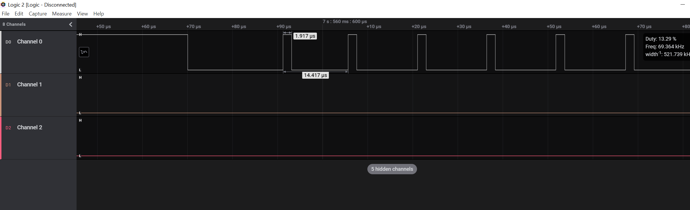
#128 Re: Cortex M0/M3/M4/M7 » 输入捕获能够捕捉最小周期为2us的pwm波吗? » 2021-08-26 20:04:39
#129 Re: Cortex M0/M3/M4/M7 » 输入捕获能够捕捉最小周期为2us的pwm波吗? » 2021-08-26 14:59:51
#130 Re: Cortex M0/M3/M4/M7 » 输入捕获能够捕捉最小周期为2us的pwm波吗? » 2021-08-26 12:36:50
#132 Re: ESP32/ESP8266 » 乐鑫 ESP32-C3 功能介绍 » 2021-08-23 00:44:35
#133 Re: DIY/综合/Arduino/写字机/3D打印机/智能小车/平衡车/四轴飞行/MQTT/物联网 » nrf52系列开发日志 » 2021-08-11 17:27:53
nrf蓝牙芯片有个很有意思的外设ppi,可编程外设互联。进一步了解得知nrf系列的外设的寄存器很不一样,nRF52832 的寄存器分为下面的三种类型。
Task :任务寄存器,可以由程序或事件触发。
Event:事件寄存器,事件可以产生中断或触发任务。
Register:普通寄存器,和一般单片机的寄存器一样。
Task 和 event 使得操作片上外设十分方便简洁,只需进行少量的配置,即可轻松运用各种外设。同时,Task 和 event 能有效减少 CPU 的占用时间,降低 CPU 的负荷。
Task 和 Event 更多的是用来和 PPI(可编程外设互连)配合使用,通过 PPI 将某个 Event和 Task 连接起来,连接后,该 Event 即可触发对应的 Task 执行相应的功能。
不知道其他蓝牙芯外设是否有同样设计,这是第一次发现这样有趣的设计,应该是为低功耗而生的设计。最近发现很多mcu芯片开始集成一些fpga类似的功能,比如rp2040的可编程io,这次的ppi也有异曲同工之妙。估计以后的芯片设计方向都会加入类此的外设。
#134 Re: ESP32/ESP8266 » ESP32DOWD外扩ESP-PSRAM64H不识别的问题 » 2021-08-11 14:23:13
@491990741
不好意思,驱动不太懂。我只是按照https://github.com/micropython/micropython/tree/master/ports/esp32编译后生成的固件就直接支持psram了。
make BOARD=UM_TINYPICO#135 Re: ESP32/ESP8266 » ESP32DOWD外扩ESP-PSRAM64H不识别的问题 » 2021-08-10 15:46:17
@491990741
我也不太了解,电路参考了tinypico的https://www.tinypico.com/tinypico-nano。具体代码实现,我知道的是在micropython里有针对tinypico的设置,你可以看一下。
#136 Re: DIY/综合/Arduino/写字机/3D打印机/智能小车/平衡车/四轴飞行/MQTT/物联网 » nrf52系列开发日志 » 2021-08-09 13:12:12
ble点灯程序功耗实测,官方的例程中有四个led和四个按键,需要把不需要的按键注释掉,只保留一个led,如下:
int main(void)
{
    // Initialize.
    log_init();
		NRF_LOG_INFO("Blinky example started.");
    leds_init();
    timers_init();
    //buttons_init();
    power_management_init();
    ble_stack_init();
    gap_params_init();
    gatt_init();
    services_init();
    advertising_init();
    conn_params_init();

    // Start execution.
    NRF_LOG_INFO("Blinky example started.");
    advertising_start();

    // Enter main loop.
    for (;;)
    {
        idle_state_handle();
    }
}
sdk_config.h中开启dcdc使能,由于模块没有外接32k晶振,使能内部rc(内部rc要比外部晶振功耗增加几个ua)。
重点优化功耗的几个参数:
广播间隔越大, 功耗越低;
广播持续时间越长,功耗越大
蓝牙BLE设备联结后,蓝牙主机会向BLE设备发送连接事件(Connection Events),BLE设备接收到连接事件后,会进行回复,以通知蓝牙主机连接通路正常。而这是BLE设备连接后最耗电的工况,所以增加连接间隔时间会降低BLE设备的功耗,但是需要注意的是,改变连接间隔时间就相应地会改变蓝牙的通讯速度。
从机延时(Slave Latency)次数,就是在连接时忽略连接事件的次数。
#define APP_ADV_INTERVAL                640                                      /**< The advertising interval (in units of 0.625 ms; this value corresponds to 40 ms). */
#define APP_ADV_DURATION                BLE_GAP_ADV_TIMEOUT_LIMITED_MAX//BLE_GAP_ADV_TIMEOUT_GENERAL_UNLIMITED   /**< The advertising time-out (in units of seconds). When set to 0, we will never time out. */

#define MIN_CONN_INTERVAL               MSEC_TO_UNITS(1000, UNIT_1_25_MS)        /**< Minimum acceptable connection interval (0.5 seconds). */
#define MAX_CONN_INTERVAL               MSEC_TO_UNITS(2000, UNIT_1_25_MS)        /**< Maximum acceptable connection interval (1 second). */
#define SLAVE_LATENCY                   0                                       /**< Slave latency. */
#define CONN_SUP_TIMEOUT                MSEC_TO_UNITS(6000, UNIT_10_MS)         /**< Connection supervisory time-out (4 seconds). */
这些参数需要综合考虑,因为参数之间是有关联的,设置不当反而会适得其反,以上设置的参数可能并不是最优的甚至是错误的,需要学习这些参数的具体原理。以下是官方给出的功耗优化建议:
https://devzone.nordicsemi.com/nordic/nordic-blog/b/blog/posts/optimizing-power-on-nrf52-designs
由于测试条件有限,万用表并不适合测量这么低功耗的射频芯片。功率分析仪可能会好些,大概用万用表测了一下,广播电流在15ua左右(有跳动但是太快测不出,官方有个理论评估在线工具:
https://devzone.nordicsemi.com/nordic/power/w/opp/2/online-power-profiler-for-ble
简单评估了一下广播功耗大概23ua: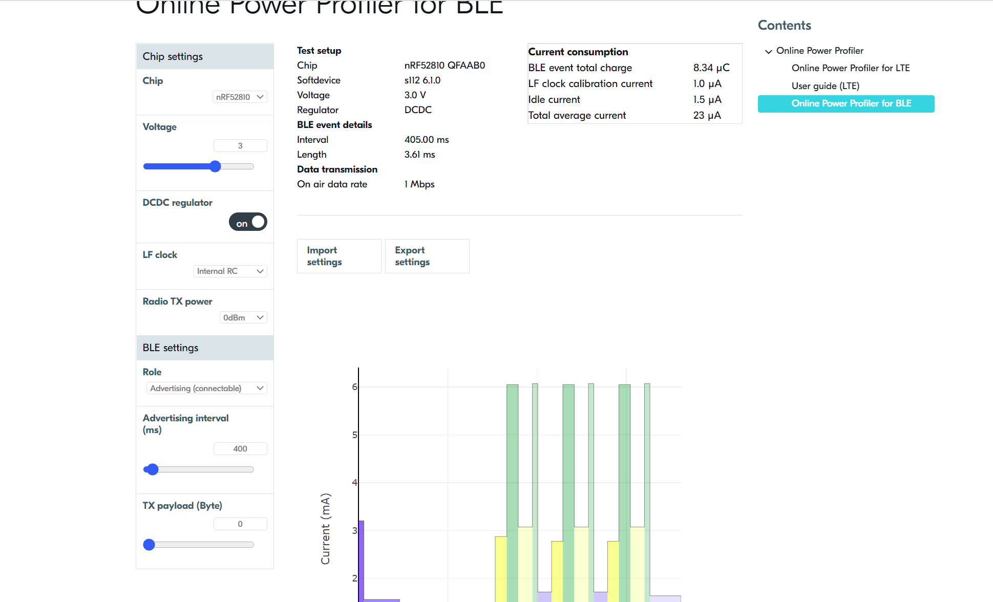
#137 Re: DIY/综合/Arduino/写字机/3D打印机/智能小车/平衡车/四轴飞行/MQTT/物联网 » nrf52系列开发日志 » 2021-08-09 12:24:05
功耗测试,看到nrf52811的手册功耗参数有点吓人,1mhz运行功耗是34.4 µA,经过实测基本符合手册,官方的点灯程序修改一下测得是2.69ma,然后除以64mhz,平均功耗是42ua,可能需要优化才能达到官方数据吧,不管了,42ua的运行功耗也是很优秀了。
#include <stdbool.h>
#include <stdint.h>
#include "nrf_delay.h"
#include "boards.h"

/**
 * @brief Function for application main entry.
 */
int main(void)
{
    /* Configure board. */
    //bsp_board_init(BSP_INIT_LEDS);

    /* Toggle LEDs. */
    while (true)
    {
//        for (int i = 0; i < LEDS_NUMBER; i++)
//        {
//            bsp_board_led_invert(i);
//            nrf_delay_ms(500);
//        }
    }
}#138 DIY/综合/Arduino/写字机/3D打印机/智能小车/平衡车/四轴飞行/MQTT/物联网 » nrf52系列开发日志 » 2021-08-08 16:47:23
- kekemuyu
- 回复: 3
作为全球蓝牙份额占比最大的nordic公司,其nrf52系列非常经典,广泛用于物联网、可穿戴设备。而且其协议栈紧跟蓝牙标准,怀疑nordic中有人参与标准的制定。开发环境非常亲民,keil、gcc、ses(SEGGER公司开发)等,开贴记录一下填一下坑。
1.keil环境下,直接用pack installer把对应的包在线安装即可
2.从nrf官方下载sdk
3.点灯
4.ble点灯
官方sdk中有examples,其中大多数例子是基于nrf52840或nrf52832的。由于我买的是nrf52811模块,所以例子需要做一些修改。
例子中的pca10056是nrf52840,pca10056e对应的是nrf52811(是官方从pca10056复制并修改了一些配置)。
点灯程序很顺利,按照自己的板子修改一下io即可。
ble点灯就不是很顺利了,遇到的问题是日志无法打印,无法发现蓝牙设备,开始以为是协议栈烧录有问题,反复折腾还是不行。后来拆开模块屏蔽罩发现没有32.768k的晶振,而协议栈工作是需要低速时钟的,由于官方例子默认是外部晶振,所以修改配置后解决问题。至此,蓝牙可以完美工作。
内部rc修改步骤:
其中source是时钟源,rc_ctiv是校准定时器间隔,rc_temp_ctiv是恒温下的软装置校准计时器间隔,accuracy是外部时钟的精度。
与四个结构体成员相关的宏定义在sdk_config.h文件下,修改相关的宏就可以设置低频时钟的来源。
1).source的宏:NRF_SDH_CLOCK_LF_SRC,置0选择NRF_CLOCK_LF_SRC_RC----内部RC振荡,置1选择NRF_CLOCK_LF_SRC_XTAL ----外部晶振。
2).rc_ctiv的宏:NRF_SDH_CLOCK_LF_RC_CTIV,选择内部RC时值为16,选择外部晶体时值为0.
3).rc_temp_ctiv:NRF_SDH_CLOCK_LF_RC_TEMP_CTIV,选择内部RC时值为2,选择外部晶体时值为0.
4).accuracy:NRF_SDH_CLOCK_LF_ACCURACY,内部RC时置选择NRF_CLOCK_LF_ACCURACY_500_PPM,选择外部晶体时根据实际参考精度设置。
ble点灯视频:
#139 Re: RISC-V » juiceVm risc-v虚拟机在esp32上运行linux kernel » 2021-08-07 16:45:18
xiaohui wrote:
kekemuyu wrote:
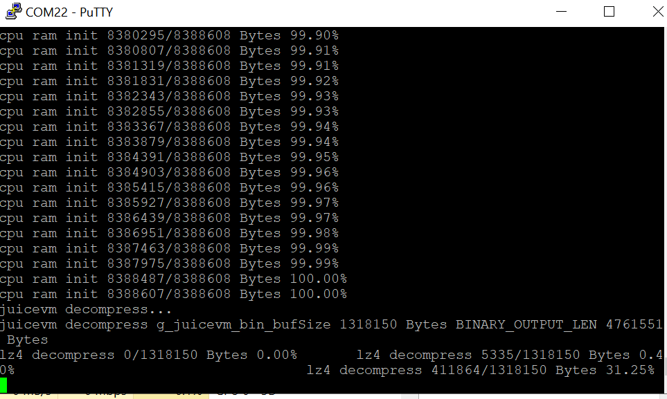
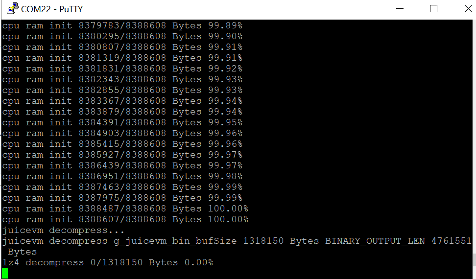
同样是WROVER-B,cpu ram init到99.60%的时候,速度突然变慢,而且卡在了下图:
/files/members/1315/Screenshot121824.png这里是在解压,压缩率有点高,解压有点慢。
感觉有点不正常啊,几个小时了,才解压31%。就像我说的在ram init到99.60%的时候突然变慢,似乎有在此时就不正常了。
#141 Re: 计算机图形/GUI/RTOS/FileSystem/OpenGL/DirectX/SDL2 » esp32的arduino环境移植lvgl » 2021-08-07 11:21:30
移植过程比较简单,不用按照官方文档(有点跟不上代码更新的速度),过程如下:
1.在arduino的ide中下载三个库:lvgl和lvgl_examples,驱动库TFT_eSPI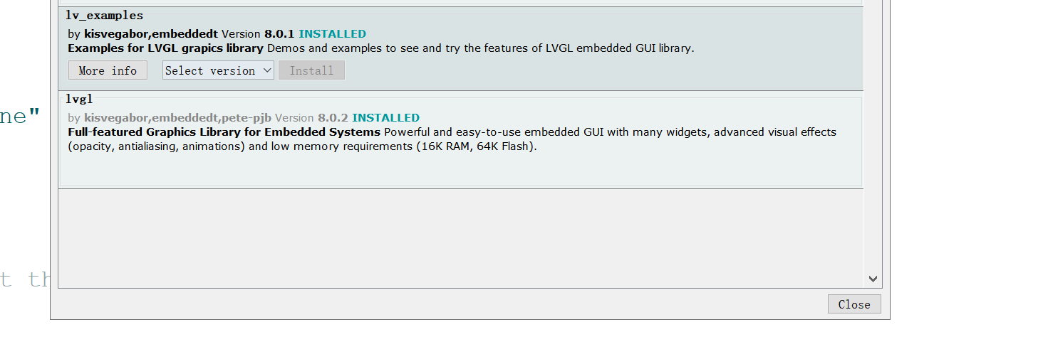
2.修改TFT_eSPI的User_Setup_Select.h文件,使能对应的驱动芯片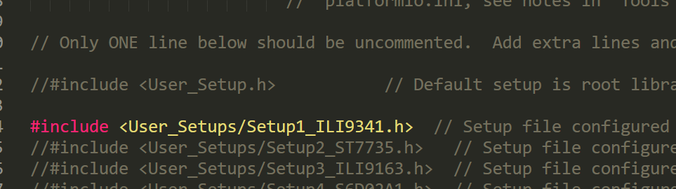
修改TFT_eSPI\User_Setups的驱动文件,修改对应管脚。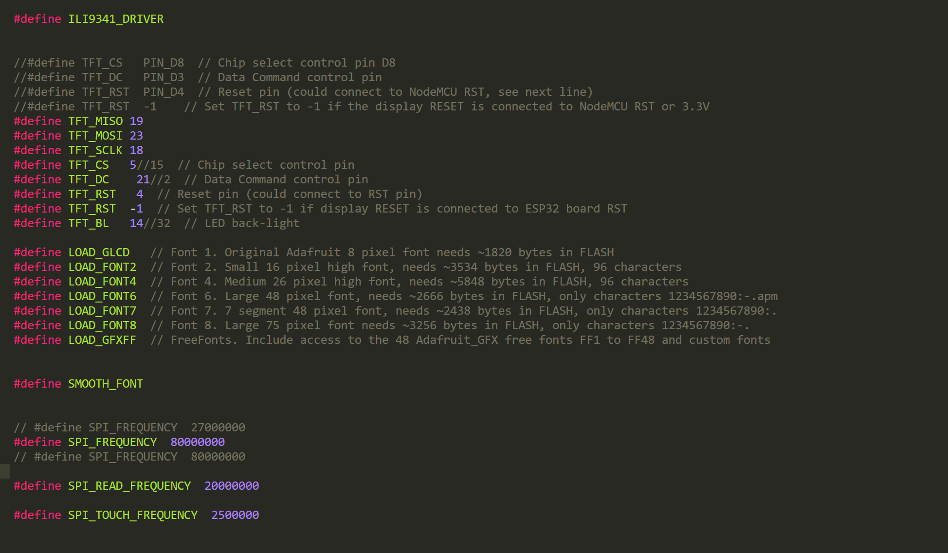
3.复制lvgl中的lv_conf_template.h改名为lv_conf.h并移植到lvgl上层目录,同样复制lvgl_examples中的lv_demo_conf_template.h改名为lv_demo_conf.h并移植到lvgl_examples上层目录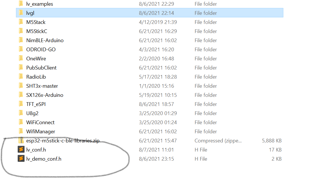
4.修改lv_conf.h和lv_demo_conf.h这两个文件,这个就是使能或禁用某些参数,按需配置即可
5.最后编译arduino对应的demo,可能或报错,说找不到某些文件,应该是lvgl_examples中的某些文件引用的路径不对,修改一下即可。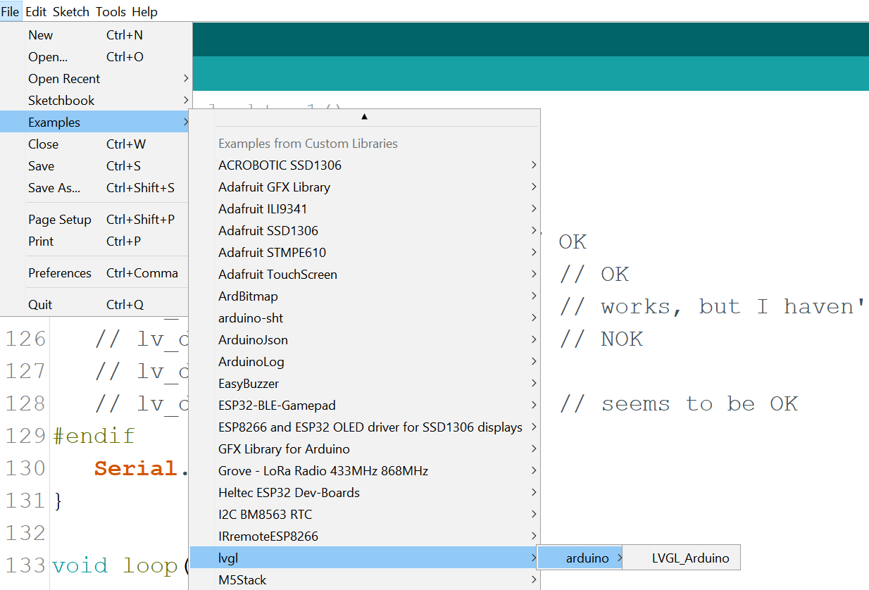
路径报错需要修改的文件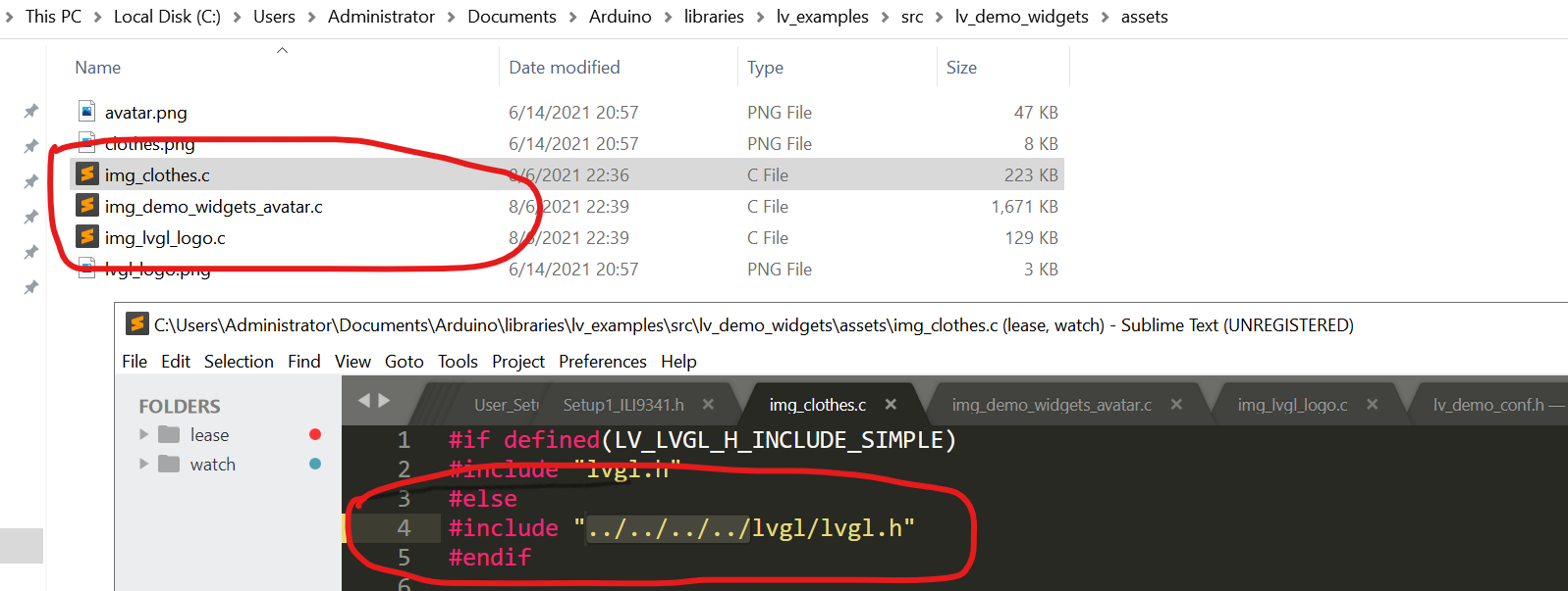

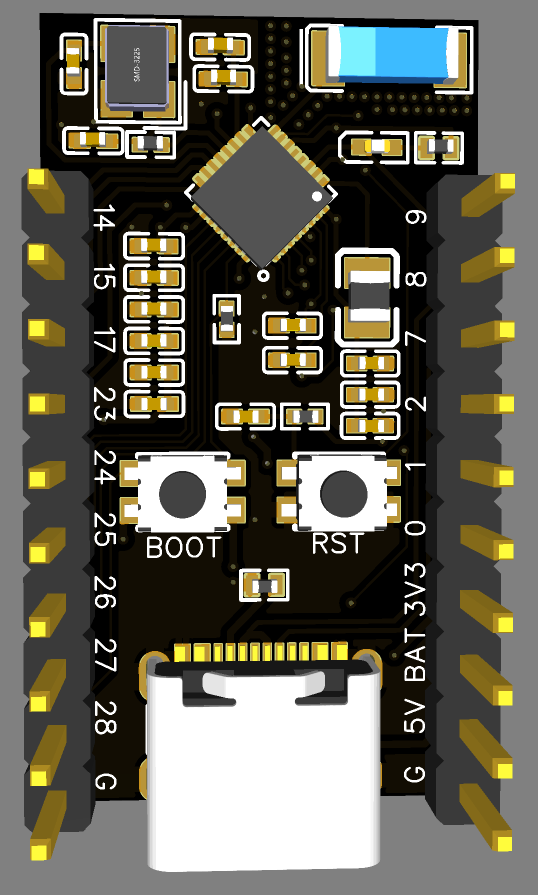
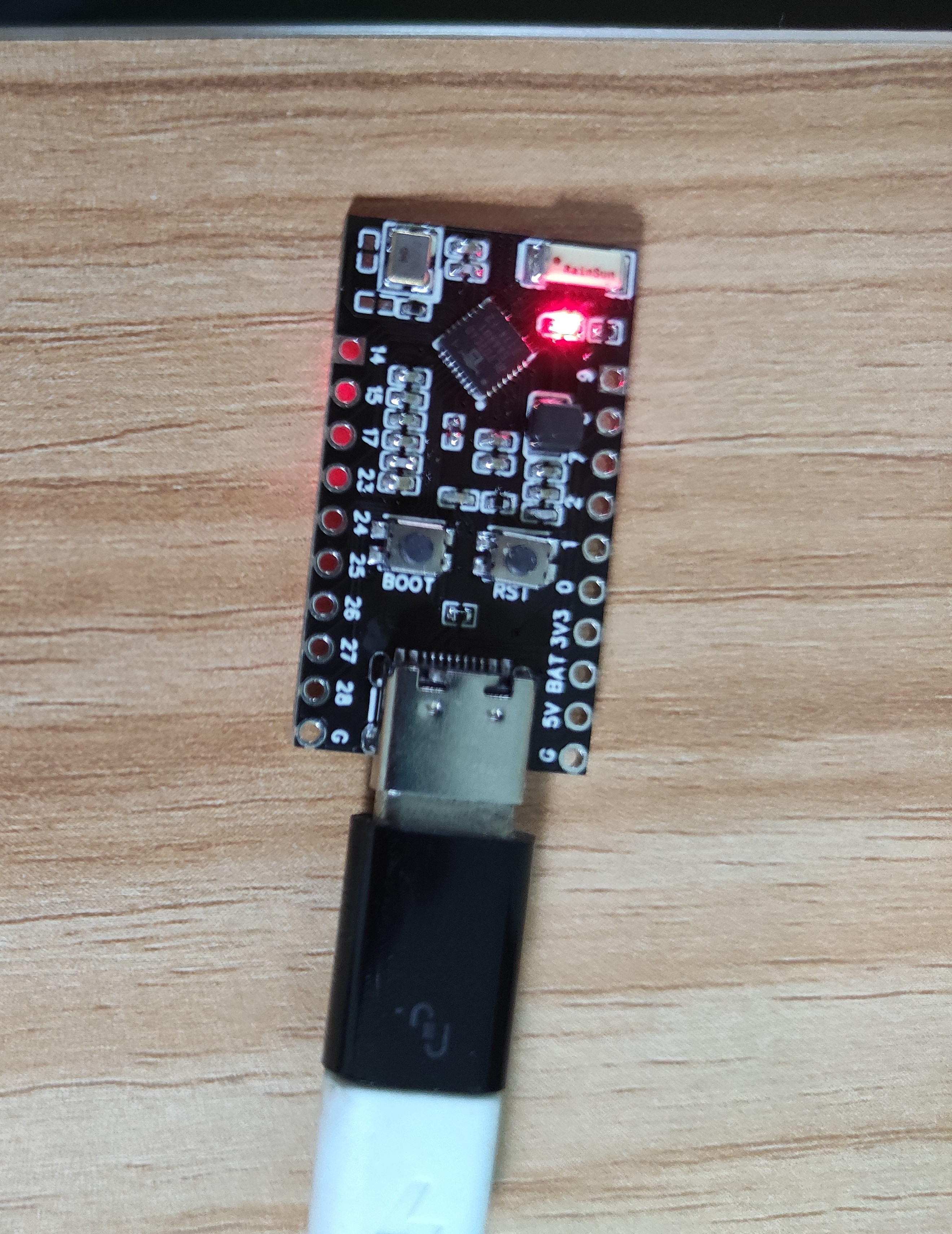
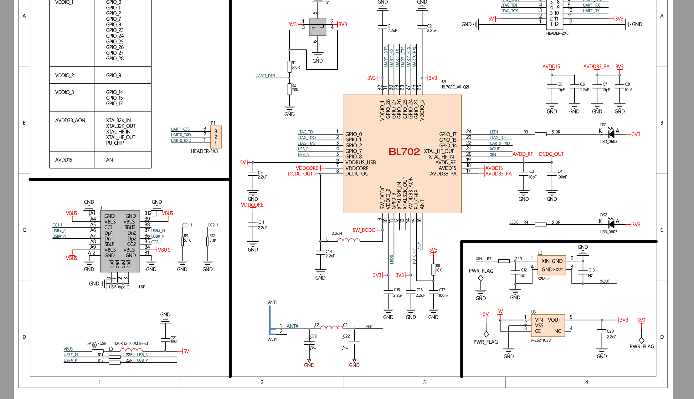
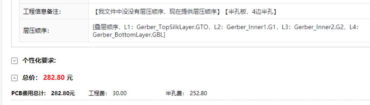
#144 Re: RISC-V » 自制博流bl702精致小板 » 2021-07-23 21:16:42
@qwert1213131
sipeed tb店,实测和手册基本一致
@metro
Gerber_PCB_LineTinyBL702.zip
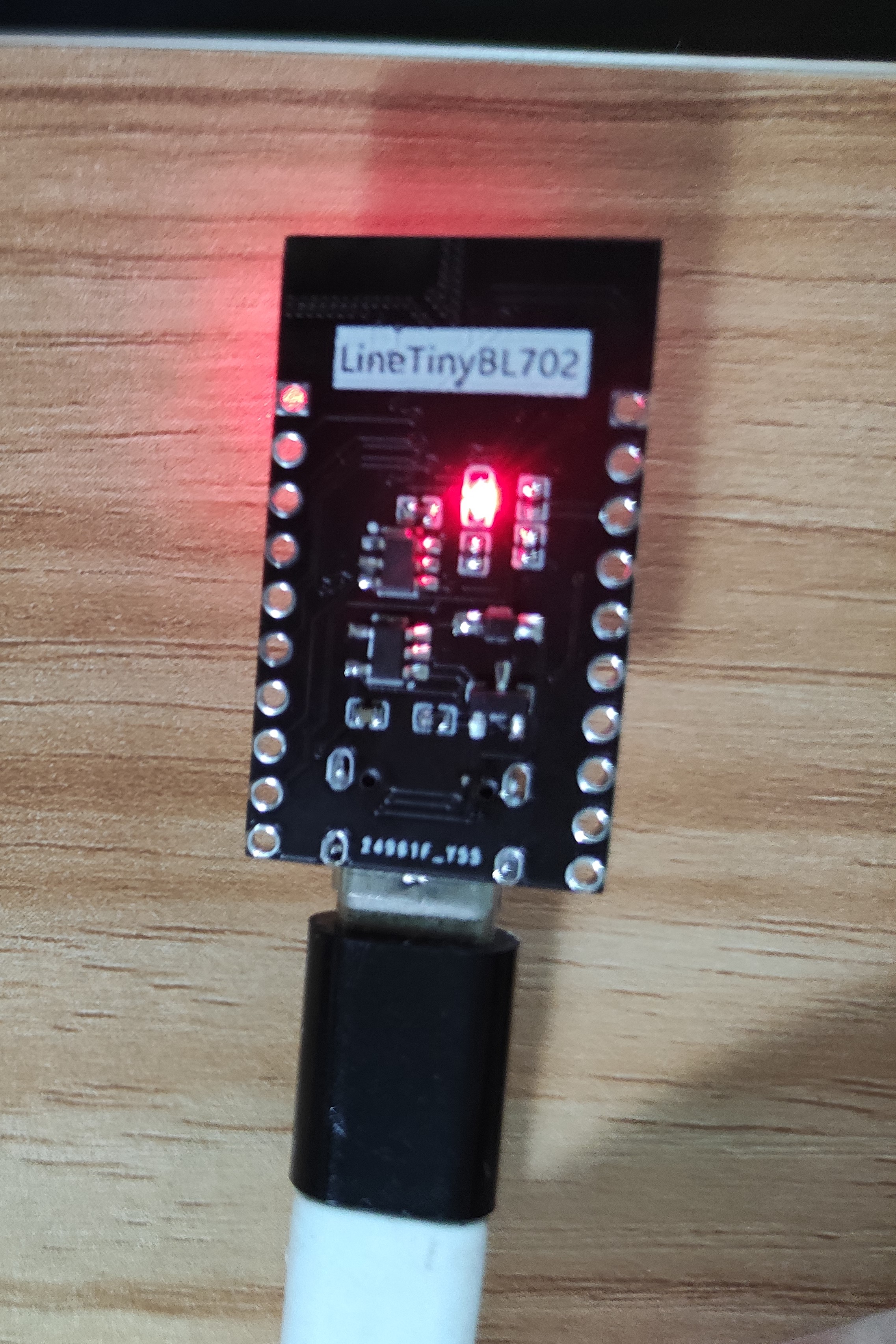
#145 RISC-V » 自制博流bl702精致小板 » 2021-07-23 11:06:31
#146 Re: 技术人生/软件使用技巧/破解经验/技术吐槽/灌水 » 玩一玩avr汇编,探究计算机的本质 » 2021-07-23 00:14:55
后面的跟贴内容可能会一直涉及编译原理的内容,有些晦涩,只有对编译原理感兴趣的同学才会感兴趣吧!无论如何编译原理是了解计算机本质的一种途径,它涉及到计算体系的各个方面,学之受益无穷。今天就让编译原理这个大棒降维打击一下表达式的求解。
让程序求解一个表达式如123+234*(12/2),应该如何出处理呢?不同的思路可能有不同的答案,这里用编译原理这把牛刀宰它。
整体思路:
词法分析->语法分析->语义分析
其中需要说明的是语义分析是包含在语法分析中的,因为用的是语法制导翻译方法。
0.文法
E->T E1
E1->op1|T fun1 E1|null
T->F T1
T1->op2 F fun1 T1| null
F->(E)|-F fun2|I
I->const fun3
op1->+fun4|-fun5
op2->*fun6|/fun6
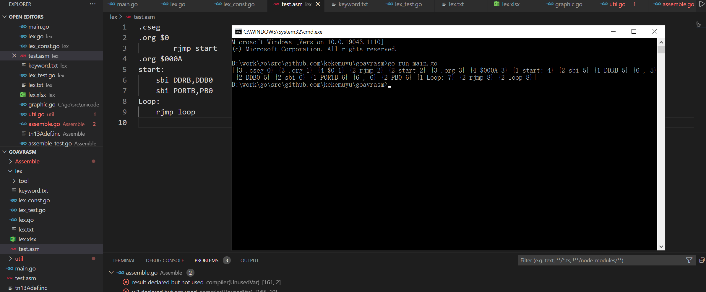
1.词法分析
词法分析是比较简单,主要分为三类:
数字:0-9
界符:( )
运算符:+,-,*,/
建立词法分析表(只是举例和代码并不匹配):
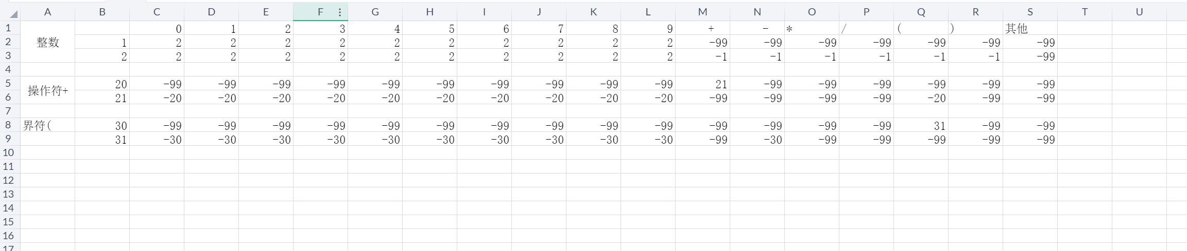
由词法分析表驱动词法解析程序,效果如下:
token结构是:
type Token struct {
Kind int //类型
Content string //值
RowNum int //行数
}
[{1 123 0} {2 + 0} {1 234 0} {2 * 0} {3 ( 0} {1 12 0} {2 / 0} {1 2 0} {3 ) 0}]
2.语法分析
核心框图:
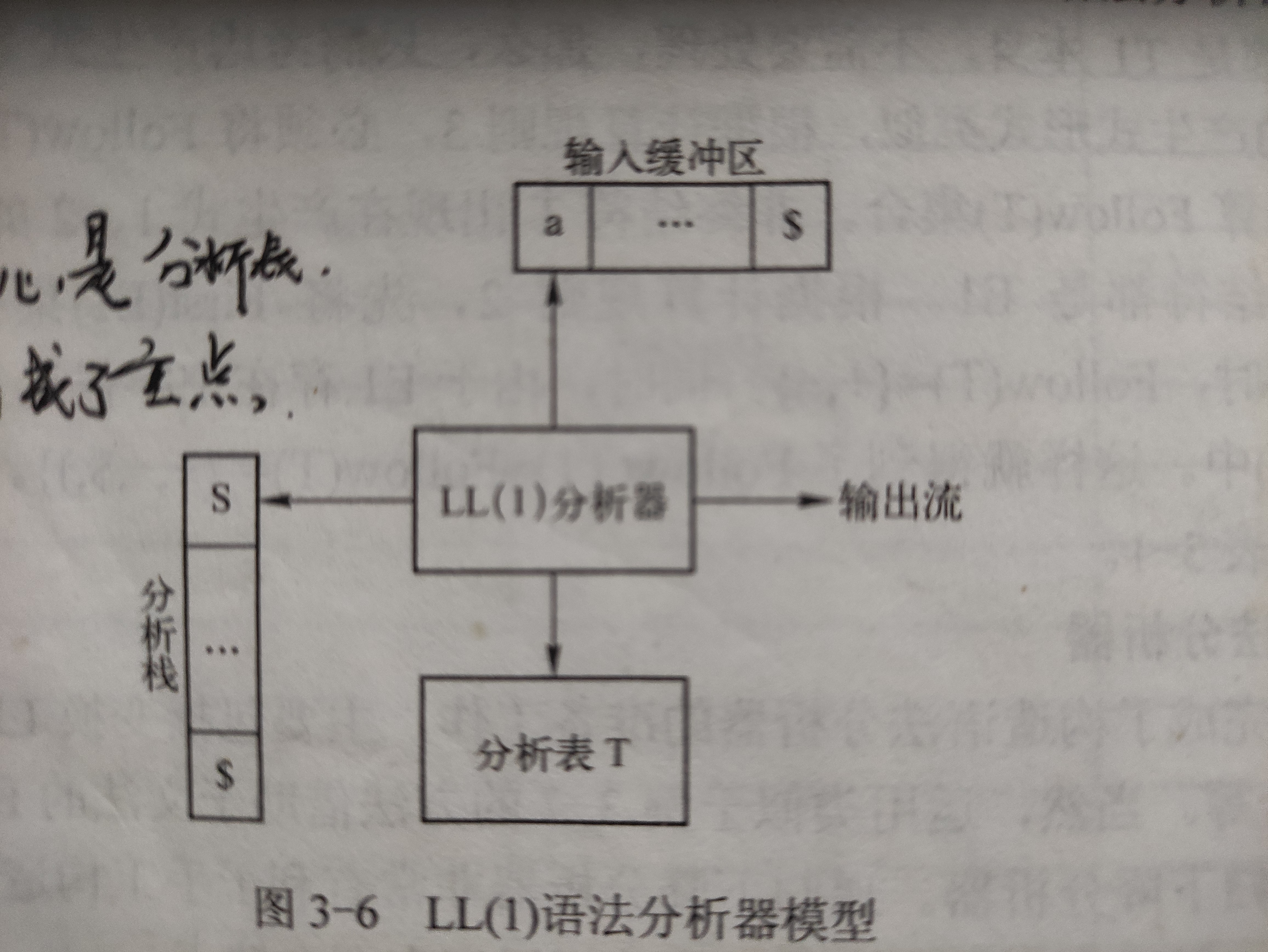
由文法规则获取first集和follow集,进而建立语法分析表:
var sParseTable = [8][8]string{
	//    +      -        *      /    const   (      )    $
	{"err", "T,E1", "err", "err", "T,E1", "T,E1", "err", "err"},                      //E
	{"op1,T,fun1,E1", "op1,T,fun1,E1", "err", "err", "err", "err", "null", "null"},   //E1
	{"err", "F,T1", "err", "err", "F,T1", "F,T1", "err", "err"},                      //T
	{"null", "null", "op2,F,fun1,T1", "op2,F,fun1,T1", "err", "err", "null", "null"}, //T1
	{"err", "-,F,fun2", "err", "err", "I", "(,E,)", "err", "err"},                    //F
	{"err", "err", "err", "err", "const,fun3", "err", "err", "err"},                  //I
	{"+,fun4", "-,fun5", "err", "err", "err", "err", "err", "err"},                   //op1
	{"err", "err", "*,fun6", "/,fun7", "err", "err", "err", "err"},                   //op2
}
分析器核心程序:
func (c *Calc) Parse() bool {
	iListPos := 0

	var ival DataStack
	for c.ParseStack.Len() != 0 && iListPos < len(c.TokenList) {
		el := c.ParseStack.Back()
		ival = el.Value.(DataStack)
		c.ParseStack.Remove(el)

		if ival.Kind == "VT" { //非终结符
			icol := "$"
			if c.TokenList[iListPos].Kind == TOKEN_KIND_CONST {
				icol = "const"
			} else if c.TokenList[iListPos].Kind == TOKEN_KIND_OPRATOR {
				icol = c.TokenList[iListPos].Content
			} else if c.TokenList[iListPos].Kind == TOKEN_KIND_SPLITE {
				icol = c.TokenList[iListPos].Content
			}
			if v, ok := c.ParseTables[Pcell{ival.Data, icol}]; ok { //查询语法分析表

				if v.Data == "err" {
					log.Fatal("row,col:", ival.Data, c.TokenList[iListPos])
				} else if v.Data == "null" {
					continue
				} else {
					tmp := strings.Split(v.Data, ",")
					for k, _ := range tmp {
						re := tmp[len(tmp)-k-1]
						kind := ""
						if isVT(re) {
							kind = "VT" //非终结
						} else if isFUN(re) {
							kind = "FUN" //语义部分
						} else {
							kind = "VN" //终结
						}
						ds := DataStack{
							Data: re,
							Kind: kind,
						}

						c.ParseStack.PushBack(ds) //反序入栈

					}
				}

			} else {
				log.Fatal("row,col:", ival.Data, c.TokenList[iListPos])
			}

		} else if ival.Kind == "VN" { //终结符
			fmt.Println("VN:", ival)
			iListPos += 1 //下一个输入流
		} else if ival.Kind == "FUN" { //语义处理
			fmt.Println("FUN:", ival)

			switch ival.Data {
			case "fun1":
				c.fun1()
			case "fun2":
				c.fun2()
			case "fun3":
				c.fun3(c.TokenList[iListPos-1].Content)
			case "fun4":
				c.fun4()
			case "fun5":
				c.fun5()
			case "fun6":
				c.fun6()
			case "fun7":
				c.fun7()
			}
			// fmt.Println("FUN END:", c.OprateDataStack.Back().Value, c.OprateSplitStack.Back().Value)

		}

		ps := make([]string, 0)
		for i := c.ParseStack.Back(); i != nil; i = i.Prev() {
			ps = append(ps, i.Value.(DataStack).Data)
		}
		fmt.Println("ps:", ps)
	}

	if c.ParseStack.Len() == 0 && iListPos == len(c.TokenList) {
		c.Result = c.OprateDataStack.Back().Value.(string)
		return true
	} else {
		return false
	}

}现在代码还有点乱,等整理后会上传至github。有词法分析和语法制导翻译的知识可以基本写一个简单的avr汇编器了。
#147 Re: 全志 SOC » 求助BGA焊接教程,以全志H3为例子,用钢网?风枪?焊油?锡膏? » 2021-07-20 11:30:01
#148 Re: 技术人生/软件使用技巧/破解经验/技术吐槽/灌水 » 玩一玩avr汇编,探究计算机的本质 » 2021-07-19 19:22:20

#152 Re: 司徒开源 » 研究FC3000掌機的開源可行性 » 2021-07-15 22:13:20
#153 Re: RISC-V » esp32上运行juicevm psram可选 » 2021-07-14 16:12:02
#154 Re: 全志 SOC » 乡下老鼠与城里老鼠交了个朋友,我来试试PWM直驱喇叭 » 2021-07-14 13:30:50
#158 Re: 司徒开源 » 研究FC3000掌機的開源可行性 » 2021-07-08 11:40:01
#159 Re: 司徒开源 » 研究FC3000掌機的開源可行性 » 2021-07-07 22:17:19
#160 Re: 司徒开源 » 研究FC3000掌機的開源可行性 » 2021-07-07 20:08:09
#161 Re: 全志 SOC » 求助BGA焊接教程,以全志H3为例子,用钢网?风枪?焊油?锡膏? » 2021-06-28 21:16:31
#166 Re: RISC-V » RISC-V代码密度相比Cortex-M差距明显 » 2021-06-22 18:06:04
#167 Re: RISC-V » 用汇编学习risc-v指令集,并在线仿真,点亮led » 2021-06-20 14:46:17

#168 Re: 司徒开源 » 研究FC3000掌機的開源可行性 » 2021-06-18 21:24:04
@司徒
只是引导linux,坛子里有人做过了。代码才3k,https://whycan.com/t_5060.html
#169 Re: 技术人生/软件使用技巧/破解经验/技术吐槽/灌水 » 玩一玩avr汇编,探究计算机的本质 » 2021-06-17 16:50:58
atiny13没有硬件串口,用软件模拟。发送模拟比较简单,接收就有点复杂了,先做发送。汇编模拟串口发送:
;
; ***********************************
; * (Add program task here)         *
; * (Add AVR type and version here) *
; * (C)2019 by Gerhard Schmidt      *
; ***********************************
;
.nolist
.include "tn13adef.inc" ; Define device ATtiny13A
.list
;
; **********************************
;        H A R D W A R E
; **********************************
;
; (F2 adds ASCII pin-out for device here)
;
; **********************************
;  P O R T S   A N D   P I N S
; **********************************
;
; (Add symbols for all ports and port pins with ".equ" here)
; (e.g. .equ pDirD = DDRB ; Define a direction port
;  or
;  .equ bMyPinO = PORTB0 ; Define an output pin)
;
; **********************************
;   A D J U S T A B L E   C O N S T
; **********************************
;
; (Add all user adjustable constants here, e.g.)
 .equ clock=9600000 ; Define the clock frequency
 .equ baudRate=115200
 .equ TX_DELAY = (clock / baudRate - 9) / 3;
 ;.equ cycle_t = 1000000 / clock
 .equ wait_cnt_10us = 10 ;10 / cycle_t / 10

;
; **********************************
;  F I X  &  D E R I V.  C O N S T
; **********************************
;
; (Add symbols for fixed and derived constants here)
;
; **********************************
;       R E G I S T E R S
; **********************************
;
; free: R0 to R14
.def rSreg = R15 ; Save/Restore status port
.def rmp = R16 ; Define multipurpose register
; free: R17 to R29
; used: R31:R30 = Z for ...
;
.def TX_BITS_NBR_TMP = R18
.def WAIT_NBR_TMP = R19
.def  BYTE_TO_TRANSMIT = R24
.def WAIT_NBR = R22
; **********************************
;           S R A M
; **********************************
;
.dseg
.org SRAM_START
; (Add labels for SRAM locations here, e.g.
; sLabel1:
;   .byte 16 ; Reserve 16 bytes)
;
; **********************************
;         C O D E
; **********************************
;
.cseg
.org 000000
;
; **********************************
; R E S E T  &  I N T - V E C T O R S
; **********************************
	rjmp Main ; Reset vector
	reti ; INT0
	reti ; PCI0
	reti ; OVF0
	reti ; ERDY
	reti ; ACI
	reti ; OC0A
	reti ; OC0B
	reti ; WDT
	reti ; ADCC
;
; **********************************
;  I N T - S E R V I C E   R O U T .
; **********************************
;
; (Add all interrupt service routines here)
;
; **********************************
;  M A I N   P R O G R A M   I N I T
; **********************************
;
Main:
	ldi rmp,Low(RAMEND)
	out SPL,rmp ; Init LSB stack pointer
; ...
;	sei ; Enable interrupts
;
; **********************************
;    P R O G R A M   L O O P
; **********************************
;
  ldi WAIT_NBR,TX_DELAY
  ldi BYTE_TO_TRANSMIT,0x0A
  rcall  SerialAsmTx_4

Loop:
    ldi WAIT_NBR,TX_DELAY
  ldi BYTE_TO_TRANSMIT,0x0A
  rcall  SerialAsmTx_4
  ldi r28,50
  rcall delay_500ms

	rjmp loop
;
; End of source code

SerialAsmTx_4:
	cli
	sbi DDRB, PB4
	ldi TX_BITS_NBR_TMP, 10
	com BYTE_TO_TRANSMIT
TxLoop_4:
        brcc Tx1_4
        cbi PORTB, PB4
Tx1_4:
        brcs TxDone_4
        sbi PORTB, PB4
TxDone_4:
        mov WAIT_NBR_TMP, WAIT_NBR
TxDelay_4:
        dec WAIT_NBR_TMP
        brne TxDelay_4
        lsr BYTE_TO_TRANSMIT
        dec TX_BITS_NBR_TMP
        brne TxLoop_4
		reti
;10 cycles,per loop
delay_500ms:
  ldi r25,wait_cnt_10us
  ldi r26,100
  ldi r27,10
loop1:
  nop
  nop
  nop
  nop
  nop
  nop
  nop
  dec r25
  brne loop1
  dec r26
  ldi r25, wait_cnt_10us
  brne loop1
  ldi r26,100
  dec r27
  brne loop1
  ldi r27,10
  dec r28
  brne loop1
  ret

;
; (Add Copyright information here, e.g.
; .db "(C)2019 by Gerhard Schmidt  " ; Source code readable
; .db "C(2)10 9ybG reahdrS hcimtd  " ; Machine code format
;
#171 Re: 司徒开源 » 研究FC3000掌機的開源可行性 » 2021-06-15 12:49:55
如果不介意编程语言,我推荐《编译器设计之路》这本书。这是一本实战的书,里面有pascal编译器的完整实现及源码。代码量不大,很适合入门。
这个编译器的源码是c++实现,源码地址:https://sourceforge.net/projects/neopascal/
#172 Re: 司徒开源 » 研究FC3000掌機的開源可行性 » 2021-06-15 00:01:53
从来不以功利目的去学习技术,只是跟随兴趣。学习汇编也是对计算机底层的兴趣,从学编程的第一天开始就对操作系统、编译原理感兴趣。
最近研究汇编也是为了学习写汇编器、编译器。前几天刚把avr的汇编器的词法分析部分写完。写汇编器之前,想参考一下开源的汇编器,发现除了gcc的,很少有人专门写一个汇编器了(除了cpu设计公司,甚至他们也是给gcc写个后端)。有意思的是看到了一个avr的开源汇编器是pascal写的,分析了一下竟然没有按照编译原理写,硬是靠自己的想法堆出来了。它的地址:http://www.avr-asm-tutorial.net/gavrasm/index_en.html,有兴趣可以看一下。
#173 Re: 司徒开源 » 研究FC3000掌機的開源可行性 » 2021-06-14 21:08:20
#174 Re: 技术人生/软件使用技巧/破解经验/技术吐槽/灌水 » 玩一玩avr汇编,探究计算机的本质 » 2021-06-14 19:25:45
#175 Re: 司徒开源 » 研究FC3000掌機的開源可行性 » 2021-06-14 14:40:32
#176 Re: 司徒开源 » 研究FC3000掌機的開源可行性 » 2021-06-13 22:38:15
#177 Re: DIY/综合/Arduino/写字机/3D打印机/智能小车/平衡车/四轴飞行/MQTT/物联网 » MySql 怎么配置数据只保存在内存中,不保存在硬盘 » 2021-06-09 21:52:17
#178 Re: 技术人生/软件使用技巧/破解经验/技术吐槽/灌水 » 玩一玩avr汇编,探究计算机的本质 » 2021-06-04 22:46:25
#179 Re: 技术人生/软件使用技巧/破解经验/技术吐槽/灌水 » 玩一玩avr汇编,探究计算机的本质 » 2021-06-04 22:30:28
#182 Re: 技术人生/软件使用技巧/破解经验/技术吐槽/灌水 » 玩一玩avr汇编,探究计算机的本质 » 2021-06-04 21:29:13
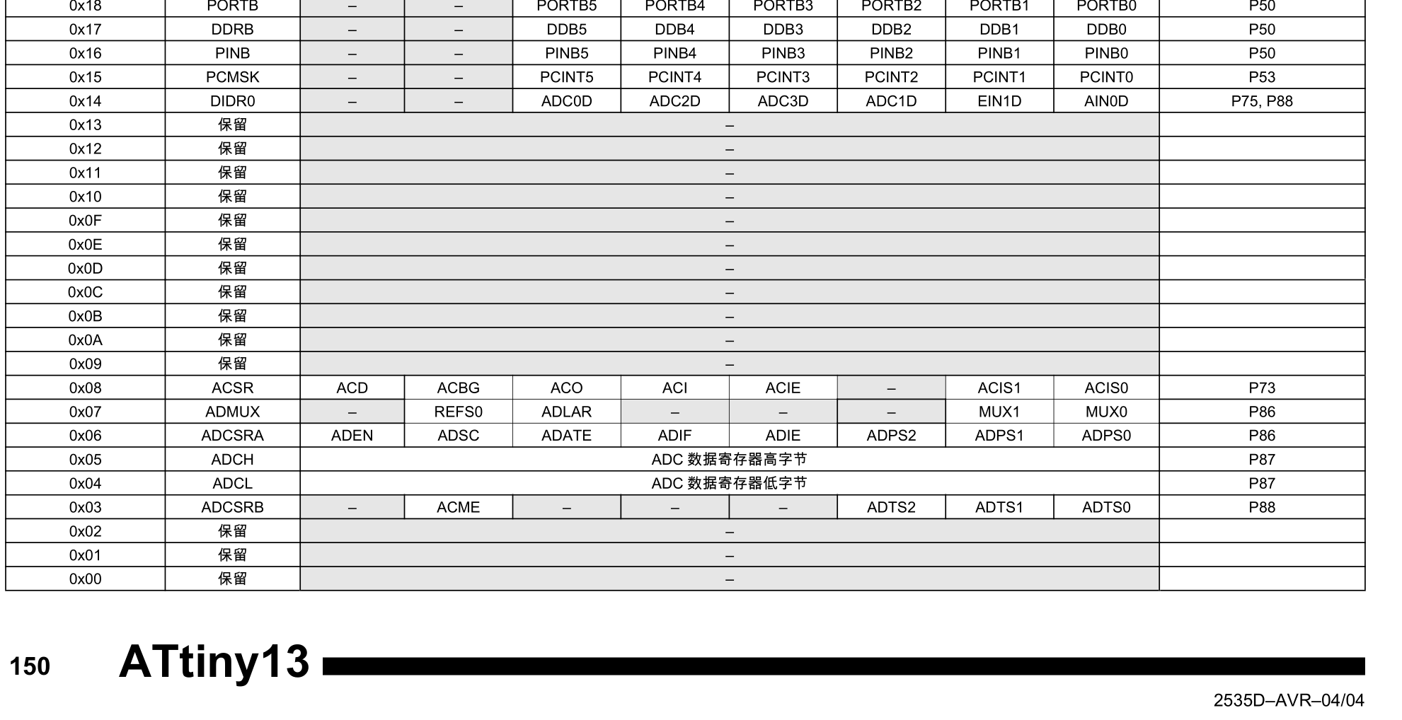
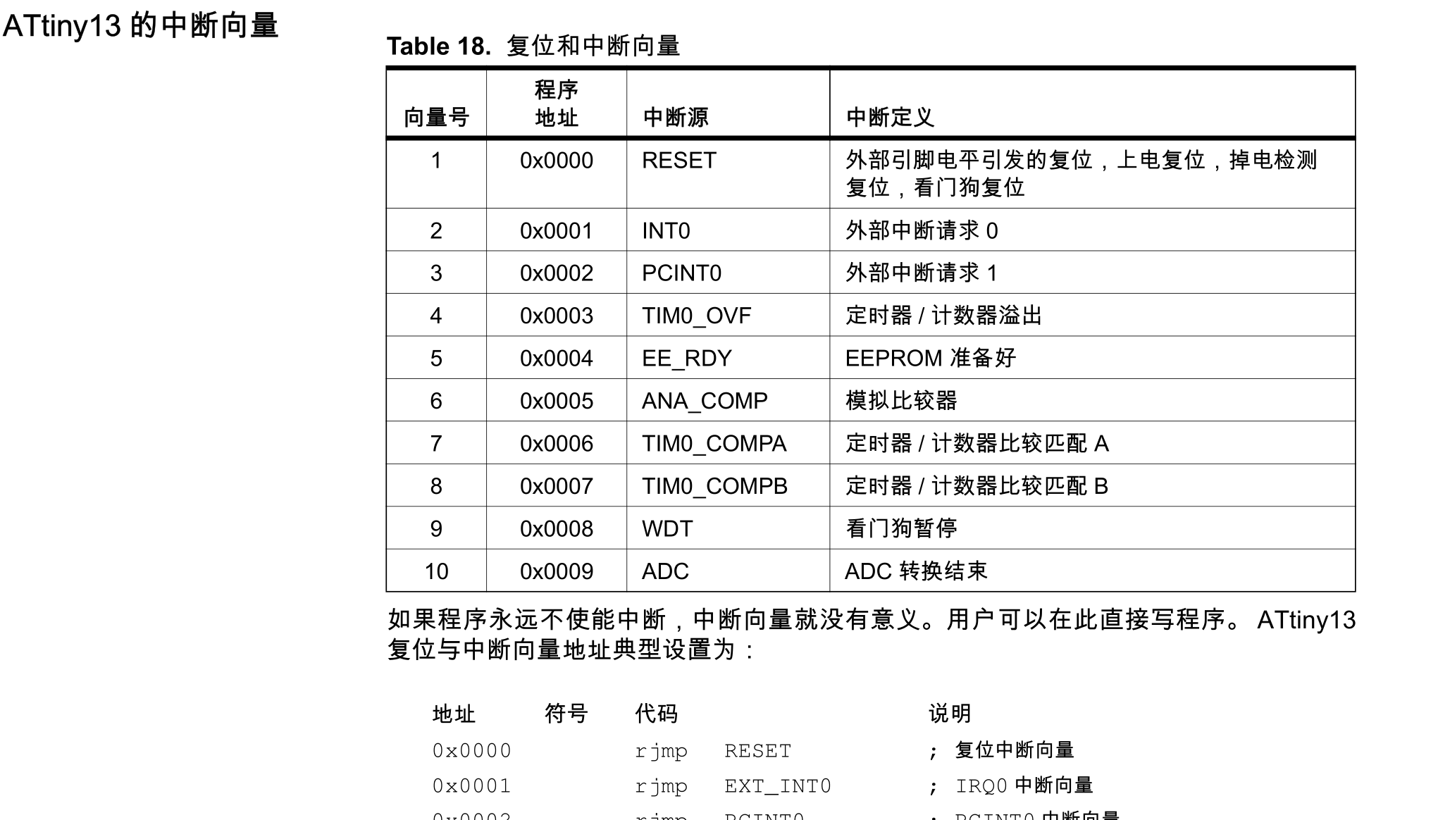
#183 技术人生/软件使用技巧/破解经验/技术吐槽/灌水 » 玩一玩avr汇编,探究计算机的本质 » 2021-06-04 21:22:40
- kekemuyu
- 回复: 14
avr单片机是很经典的8位mcu,因为arduino的火爆,直到现在依然很流行。在8位单片机开创性的引入了32个寄存器,两级流水线,risc结构直接降维打击了同时代的8051。以avr为例,探究一下计算机的本质。研究计算机原理可以看书,也可以做试验。我选择从试验开始,这样更有趣一些。现在做实验简单多了,各种虚拟环境和ide非常丰富。我选择用真机做实验,这样更实用和真实一些。
首先介绍一下用到的工具:
1.atmel studio,主要用它编译和仿真汇编代码
2.硬件,一个avr最小系统,我选择attiny13,研究汇编够用了
3.烧写器usb isp,以及烧写工具智峰下载器
4.avr汇编指令集手册,以及attiny13的手册
开篇上点灯程序:
.cseg
.org $0
        rjmp start
.org $000A
start:
	sbi DDRB,DDB0
	sbi PORTB,PB0
Loop:
rjmp loop机器码对照:
                                 .cseg
                                 .org $0
000000 c009                              rjmp start
                                 .org $000A
                                 start:
00000a 9ab8                      	sbi DDRB,DDB0
00000b 9ac0                      	sbi PORTB,PB0
                                 Loop:
00000c cfff                      	rjmp loop
hex格式
:020000020000FC
:0200000009C035
:06001400B89AC09AFFCF6C
:00000001FF
flash memery快照:
prog 0x0000  09 c0 ff ff ff ff ff ff ff ff ff ff ff ff ff ff ff ff ff ff b8 9a c0 9a
prog 0x0018  ff cf ff ff ff ff ff ff ff ff ff ff ff ff ff ff ff ff ff ff ff ff ff ff
hex格式解释:
数据个数 地址 类型 数据 crc校验
: 00 0000 00 000000... 00
下载器使用hex文件烧录数据到avr,中间经过了解析hex文件的过程。主要是取出机器码并烧录到flash。
avr的汇编格式是:
操作码---操作数/地址/空---操作数/地址/空
整条指令是16位或是32位(32位很少)
avr整个工作过程是,从mcu上电开始,pc指向flash的0地址,开始取指-执行重复下去,直至结束。我们每天使用的电脑办公、手机刷视频,在cpu看来都是一堆01010101。
我们可以用汇编开发mcu,也可以直接用机器码开发。上古计算机就是机器码编程,那时候是没有falsh,直接把01代码用纸带打孔的方式来表示,也就是说纸带相当于falsh。即使现在用机器码开发,比那时候也简单多了,直接在电脑上查询寄存器的地址并转为相应的机器码,然后烧进falsh即可。
#184 技术人生/软件使用技巧/破解经验/技术吐槽/灌水 » 为什么mcu的第一条指令必须是跳转指令 » 2021-06-04 18:37:14
- kekemuyu
- 回复: 7
今天研究了一下avr的汇编指令,发现第一条指令必须要是rjmp或其他跳转(跳转到主程序),否则程序就跑飞了。把主程序放到falsh的$0000000位置也不行。
cpu不是从flash的0位置顺序读取指令执行吗? 为什么第一条必须是跳转才行?
正确代码:
.org 000000
	rjmp start
	nop
start:
	ldi r16,0xFF
	out DDRB,r16
	sbi PORTB,PB0
Loop:

	rjmp loop
错误:
start:
	ldi r16,0xFF
	out DDRB,r16
	sbi PORTB,PB0
Loop:

rjmp loop#186 技术人生/软件使用技巧/破解经验/技术吐槽/灌水 » Raspberry Pi开售RP2040微控制器芯片 售价1美元 » 2021-06-01 23:02:26
- kekemuyu
- 回复: 5
今年早些时候,Raspberry Pi基金会宣布推出4美元的Raspberry Pi Pico和RP2040微控制器用于嵌入式开发。现在,RP2040芯片正在通过他们的经销商以仅1美元的价格出售,供那些想用这种树莓派芯片构建自己的电子产品的人使用。
1美元的RP2040芯片包含两个133MHz的ARM Cortex-M0+内核,可以运行FreeRTOS和MicroPython等软件。除了这两个嵌入式内核外,还自带264KB的内存和对这种类型的控制器的所有常见I/O接口的支持。
树莓派基金会宣布,他们今年已经运送了超过60万块Raspberry Pi Pico单板,还有另外70万块的订单等待交付。同时,更多的创作者和其他企业一直在寻求使用RP2040芯片建立自己的产品,这让他们现在可以以低至1美元的单件销售价格提供该芯片。
预计到今年秋天RP2040芯片将 "大量上市"。关于RP2040供应的更多细节请查阅RaspberryPi.org。
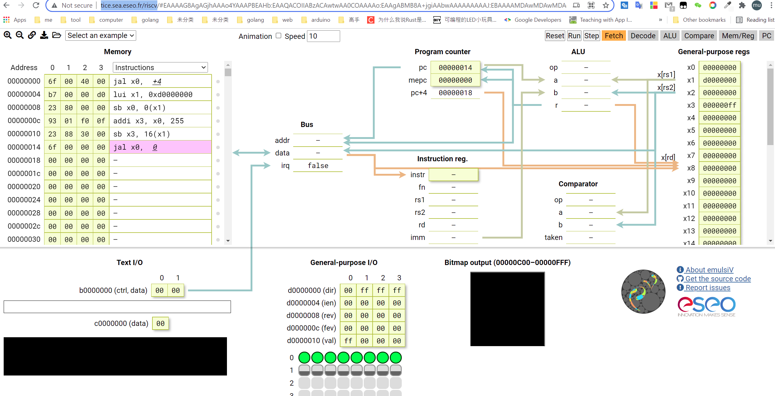
#189 RISC-V » 用汇编学习risc-v指令集,并在线仿真,点亮led » 2021-06-01 20:39:36
- kekemuyu
- 回复: 12
首先在线仿真地址:http://tice.sea.eseo.fr/riscv/,选择这个主要是因为比较好玩直观。
这个模拟器是支持gnu的编译器的,所以先安装编译器:
sudo apt install gcc-riscv64-unknown-elf模拟器gpio寄存器: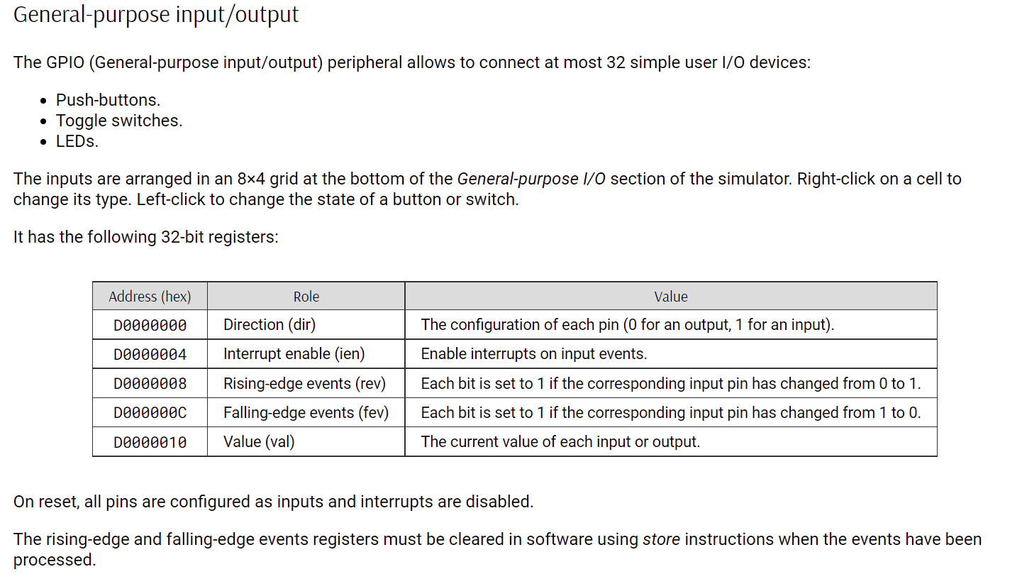
点灯程序:
/*
 * Configure the GPIO with:
 * - Byte 0: 8 LEDs
 * - Byte 1: 8 toggle switches
 */

    .text

    .global __reset

__reset:
    j start

start:
    li x1, 0xd0000000
    /* Set first GPIO byte as outputs */
    sb x0, (x1)

    li x3, 0xff
    sb x3, 0x10(x1)
    j .

    .section gpio_config, "a"

leds: .byte 3, 3, 3, 3, 3, 3, 3, 3
sws:  .byte 2, 2, 2, 2, 2, 2, 2, 2
编译文件:
riscv64-unknown-elf-gcc -march=rv32i -mabi=ilp32 -c -o led.o led.s连接成elf文件:
riscv64-unknown-elf-gcc -march=rv32i -mabi=ilp32 -nostdlib -T rv32e.ld -o led.elf led.o连接文件rv32e.ld
ENTRY(__reset)

MEM_SIZE    = 4K;
STACK_SIZE  = 512;
BITMAP_SIZE = 1K;

SECTIONS {
    . = 0x0;

    .text : {
        *(vectors)
        *(.text)
        __text_end = .;
    }

    .data   : { *(.data) }
    .rodata : { *(.rodata) }

    __global_pointer = ALIGN(4);

    .bss ALIGN(4) : {
        __bss_start = .;
        *(.bss COMMON)
        __bss_end = ALIGN(4);
    }

    . = MEM_SIZE - STACK_SIZE - BITMAP_SIZE;

    .stack ALIGN(4) : {
        __stack_start = .;
        . += STACK_SIZE;
        __stack_pointer = .;
    }

    .bitmap ALIGN(4) : {
        __bitmap_start = .;
        *(bitmap)
    }

    __bitmap_end = __bitmap_start + BITMAP_SIZE;
}
生成intel格式hex:
riscv64-unknown-elf-objcopy -O ihex led.elf led.hex最后附上在线仿真器的文档说明:http://tice.sea.eseo.fr/riscv/doc/
#190 Re: 全志 SOC » 全志D1芯片之终极探索 » 2021-05-30 10:33:24
#194 Cortex M0/M3/M4/M7 » 淘宝的stlink坏了,还能拯救一下吗?(已解决) » 2021-05-18 18:31:07
- kekemuyu
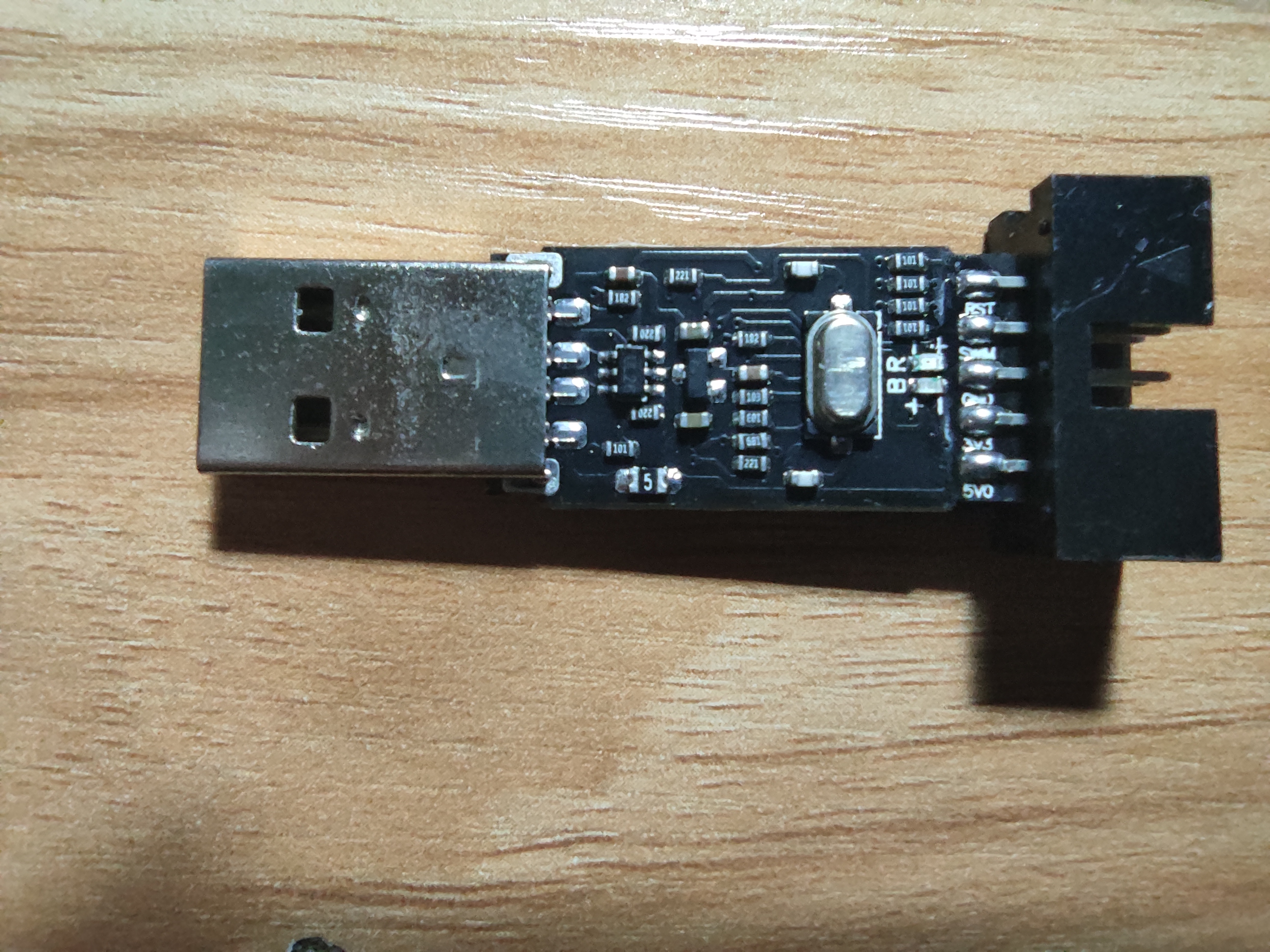
- 回复: 5
芯片被打磨掉了,不知道哪位大神知道型号。问题是电脑突然不识别设备了,显示未知设备。可能是有一次调试芯片时正负接反了导致。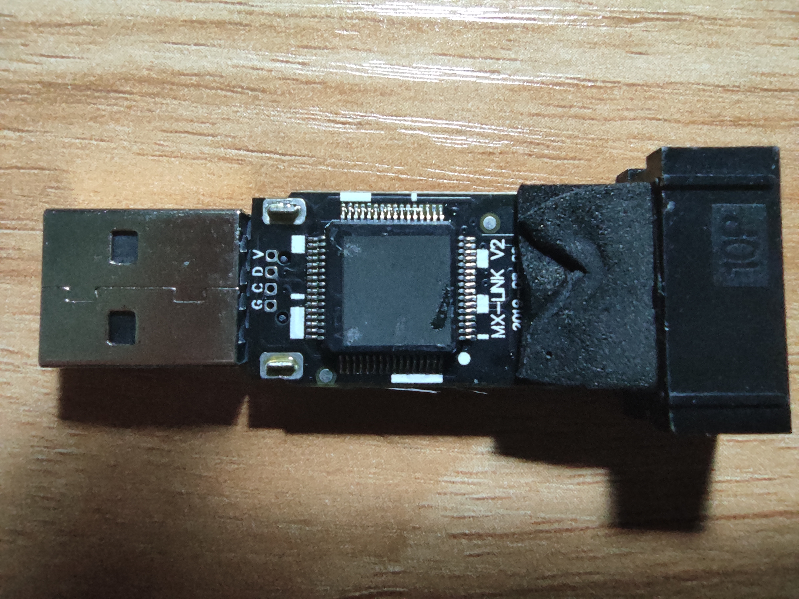
 st
st
stm32f103c8t6的stlink固件:
ST-Link固件V2.J16.S4.hex.7z
#195 Re: 技术人生/软件使用技巧/破解经验/技术吐槽/灌水 » 分布式串口透传服务器(开源) » 2021-05-18 11:35:53
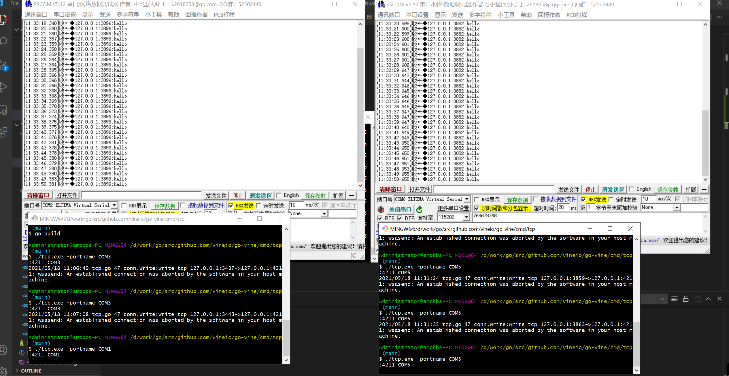
#196 Re: 技术人生/软件使用技巧/破解经验/技术吐槽/灌水 » 分布式串口透传服务器(开源) » 2021-05-16 21:58:32
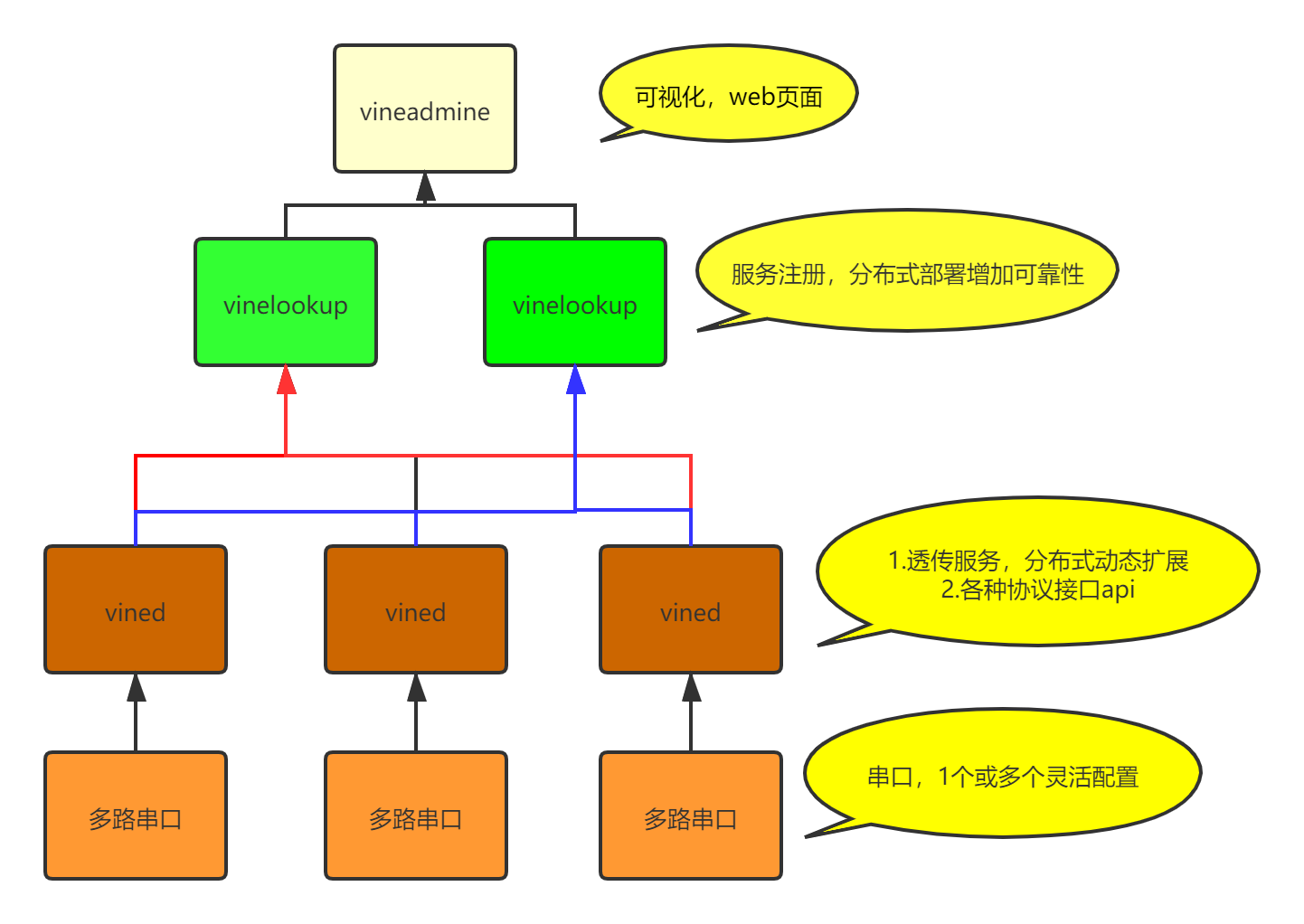
#197 Re: 技术人生/软件使用技巧/破解经验/技术吐槽/灌水 » 分布式串口透传服务器(开源) » 2021-05-16 18:20:10
microxp wrote:
开源吗
开源,刚创建了个仓库:
https://github.com/vineio/vine
#199 Re: 站务公告/网站建设 » 看不到当天的帖子回复 » 2021-05-15 21:22:02
#200 站务公告/网站建设 » 看不到当天的帖子回复 » 2021-05-15 20:21:17
东莞哇酷科技有限公司开发