#1 Re: 工业芯 匠芯创 » d133的rtp如何配置? » 2025-04-18 11:23:01
#2 Re: 工业芯 匠芯创 » Luban_Lite适配电阻屏遇到很多问题 » 2025-04-18 10:26:16


#5 Re: NB-IoT/2G模块/4G模块/GPRS模块/GPS/北斗 » ML307A的https库使用问题。 » 2025-03-28 17:06:09
联系到了一家代理的技术支持,告知这个问题。给了1.5.0的sdk,之前用的是1.4.6版本的。
使用该版本sdk,可正常进行https连接,用的是ssl无身份验证方式,可以成功,没试单向或双向证书验证。
另有两个问题记录下。
设置https的header,有cm_httpclient_specific_header_set()和cm_httpclient_custom_header_set()两个函数,不知道有啥区别,最后用了specific这个函数。想多次调用这个函数设置多个header项,发现只有最后一个能成功,后来才明白,需要一次性设置。header字符串里每个子项之间用\r\n间隔。
这个在文档里没有写明。
上电后参考例程里,等待网络通讯正常且同步ntp日期后,才进行https发送。结果第一次https发送有几率返回650,在第一https发送前加了5秒延时后问题解决。
#6 NB-IoT/2G模块/4G模块/GPRS模块/GPS/北斗 » ML307A的https库使用问题。 » 2025-03-24 09:37:59
- Gentlepig
- 回复: 3
/**
 * @brief 创建客户端实例
 *
 * @param [in] url              服务器地址(服务器地址url需要填写完整,例如(服务器url仅为格式示例)"https://39.106.55.200:80")
 * @param [in] callback         客户端相关回调函数(使用cm_httpclient_sync_request()同步接口可忽略该参数,传NULL即可)
 * @param [out] handle          实例句柄
 *
 * @return 0 成功/其他 失败(见cm_httpclient_ret_code_e)
 *
 * @details 创建客户端实例
 */
cm_httpclient_ret_code_e cm_httpclient_create(const uint8_t *url, cm_httpclient_event_callback_func callback, cm_httpclient_handle_t *handle);
例程是用这个函数连接百度网站,是https get。
ret = cm_httpclient_create((const uint8_t *)"https://www.baidu.com", __cm_httpclient_callback, &client);          //创建客户端实例
cm_httpclient_sync_param_t param = {HTTPCLIENT_REQUEST_GET, (const uint8_t *)"/", 0, NULL};          //GET方法,必须设置请求路径
ret = cm_httpclient_sync_request(client, param, &response);                         //发送请求,同步接口
且设置了ssl验证方法为单向验证,且设置了证书。可以成功get百度。
试过改成ssl验证方式为无身份验证,也可以成功get百度。
但是,我换成其他https网站,比如https:www.bing.com,或者其他,大都是无法成功https get的,直接返回个650错误。无论我设置无身份验证还是设单项验证+设置证书。
如果改为http get,则大都能收到返回,比如400.
这是为什么呢?按说这个作为4g模组,比如客户纯当at模组来用,应该能实现https连接吧。
看例程里有阿里云相关,看了下,没直接用这套cm_httpclient_create,而是直接用的lwip里的tcp相关。
#7 Re: NB-IoT/2G模块/4G模块/GPRS模块/GPS/北斗 » ml307a csdk,串口打印数和预想的不一样。 » 2025-03-19 13:02:45
void uartPrintf(char *str, ...)
{
    static char s[600];        //这个需要根据实际情况修改
    va_list args;
    int len;
    if ((str == NULL) || (strlen(str) == 0))
        return;
    va_start(args, str);
    len = vsnprintf((char*)s, 600, str, args);
    va_end(args);
    cm_uart_write(OPENCPU_MAIN_UART, s, len, 1000);
}
这是参照例程写的uartPrintf函数。
#8 NB-IoT/2G模块/4G模块/GPRS模块/GPS/北斗 » ml307a csdk,串口打印数和预想的不一样。 » 2025-03-19 08:55:21
- Gentlepig
- 回复: 2
搜了下,好像用的是freertos。
在我自己建的一个任务里调用这个函数,每调用一次,sampleIndex自加一。结果用uartPrintf()打印currentAdd和sampleIndex和预想的不一样。
currentAdd和sampleIndex,都声明为全局变量。
    currentAdd += sampleIndex;      //暂时这样计数显示,需要改
    uartPrintf("sampleIndex:%d ", sampleIndex);
    uartPrintf("currentAdd:%d ", currentAdd);
    uartPrintf("sampleIndex:%d, currentAdd:%d ", sampleIndex, currentAdd);
    uartPrintf("sampleIndex:%d ", sampleIndex);
    uartPrintf("currentAdd:%d ", currentAdd);
    uartPrintf("currentAdd:%d, sampleIndex:%d \r\n", currentAdd, sampleIndex);
sampleIndex:0 currentAdd:0 sampleIndex:0, currentAdd:0 sampleIndex:0 currentAdd:0 currentAdd:0, sampleIndex:0
sampleIndex:1 currentAdd:0 sampleIndex:1, currentAdd:1 sampleIndex:1 currentAdd:0 currentAdd:0, sampleIndex:1
sampleIndex:2 currentAdd:0 sampleIndex:2, currentAdd:3 sampleIndex:2 currentAdd:0 currentAdd:0, sampleIndex:3
sampleIndex:3 currentAdd:0 sampleIndex:3, currentAdd:6 sampleIndex:3 currentAdd:0 currentAdd:0, sampleIndex:6
sampleIndex:4 currentAdd:0 sampleIndex:4, currentAdd:10 sampleIndex:4 currentAdd:0 currentAdd:0, sampleIndex:10
sampleIndex:5 currentAdd:0 sampleIndex:5, currentAdd:15 sampleIndex:5 currentAdd:0 currentAdd:0, sampleIndex:15
sampleIndex:6 currentAdd:0 sampleIndex:6, currentAdd:21 sampleIndex:6 currentAdd:0 currentAdd:0, sampleIndex:21
sampleIndex:7 currentAdd:0 sampleIndex:7, currentAdd:28 sampleIndex:7 currentAdd:0 currentAdd:0, sampleIndex:28 而且,多次打印,前后uartPrintf()打印的都不一样。
#10 Re: 工业芯 匠芯创 » D133EBS这个芯片性能如何?跟STM32哪款芯片对比呢? » 2025-03-03 08:32:33
#11 Re: 工业芯 匠芯创 » 移植FlashDB的问题。 » 2025-03-03 08:31:17
#12 Re: 工业芯 匠芯创 » D133EBS这个芯片性能如何?跟STM32哪款芯片对比呢? » 2025-02-28 10:48:12
#13 Re: 工业芯 匠芯创 » 购买的新的D133EBS芯片如何烧录SDK? » 2025-02-28 10:46:46
#15 8051/STC8/AT89C51/N76E003 » 请教,avr单片机例程,不明白这个先乘1000再除1000有什么作用。 » 2025-02-24 08:33:13
- Gentlepig
- 回复: 7
	/*
	 * Find AVCC based on the fact that we know the bandgap voltage.
	 * To avoid excessive rounding we multiply 1024 by 1000 before dividing
	 * with the ADC result and then divide the result by 1000 afterwards.
	 * the final result is the supply voltage in millivolts.
	 */
	supply_voltage = ((BG_VOLTAGE * ((1024000) / bandgap)) / 1000);
例程是将VCC作为参考电压,采集内部1.1V电压的adc值,倒推Vcc电压值。
因为是10位adc,所以满量程是1024,BG_VOLTAG是内部1.1V电压值,是1100. bandgap是测量内部1.1电压得到的adc值。
好奇这里为什么先是1024放大1000倍,最后结果再除1000. 要是说为了避免丢掉四舍五入,但感觉结果还是会舍弃小数位的。
为何不直接这样?
supply_voltage = BG_VOLTAGE * 1024 / bandgap;#16 Re: DIY/综合/Arduino/写字机/3D打印机/智能小车/平衡车/四轴飞行/MQTT/物联网 » 单片机外接pca8565,利用它的定时器功能,每10秒差大约2毫秒的误差? » 2025-02-20 13:09:32
#17 DIY/综合/Arduino/写字机/3D打印机/智能小车/平衡车/四轴飞行/MQTT/物联网 » 单片机外接pca8565,利用它的定时器功能,每10秒差大约2毫秒的误差? » 2025-02-20 09:40:33
- Gentlepig
- 回复: 2
单片机利用Pca8565的定时器功能,每10秒拉低单片机的外部中断引脚,单片机中断函数里利用串口发数。
发现每次比预想的10秒少2毫秒。
改成1秒定时器后的PC上串口收到的数据如下:
[09:36:19.831]收←◆AA BB CC
[09:36:20.831]收←◆AA BB CC
[09:36:21.831]收←◆AA BB CC
[09:36:22.830]收←◆AA BB CC
[09:36:23.831]收←◆AA BB CC
[09:36:24.830]收←◆AA BB CC
[09:36:25.830]收←◆AA BB CC
[09:36:26.830]收←◆AA BB CC
[09:36:27.830]收←◆AA BB CC
[09:36:28.829]收←◆AA BB CC
[09:36:29.830]收←◆AA BB CC
[09:36:30.829]收←◆AA BB CC
[09:36:31.829]收←◆AA BB CC
[09:36:32.829]收←◆AA BB CC
[09:36:33.829]收←◆AA BB CC
[09:36:34.828]收←◆AA BB CC
[09:36:35.828]收←◆AA BB CC
[09:36:36.828]收←◆AA BB CC
[09:36:37.828]收←◆AA BB CC
[09:36:38.827]收←◆AA BB CC
[09:36:39.828]收←◆AA BB CC
[09:36:40.827]收←◆AA BB CC
[09:36:41.827]收←◆AA BB CC
[09:36:42.827]收←◆AA BB CC
[09:36:43.827]收←◆AA BB CC
[09:36:44.826]收←◆AA BB CC
[09:36:45.827]收←◆AA BB CC
[09:36:46.826]收←◆AA BB CC
[09:36:47.826]收←◆AA BB CC
[09:36:48.826]收←◆AA BB CC
[09:36:49.826]收←◆AA BB CC #18 Re: 全志 SOC » t113s3在uboot里选中了disp2_sunxi,设备树选了个tft08006,我在驱动里加了个死循环,结果没停下来... » 2025-01-06 15:20:28
根据信息里的reloc pc,利用objdum -S u-boot,进行反汇编,查看报错行数,定位到是:
* disable irq type */
     1 static void spi_disable_irq(u32 bitmap, void __iomem *base_addr)
     2 {
     5     u32 reg_val = readl(base_addr + SPI_INT_CTL_REG);
     6
     7     bitmap &= SPI_INTEN_MASK;
     8     reg_val &= ~bitmap;
     9     writel(reg_val, base_addr + SPI_INT_CTL_REG);
    10 }
该函数的第一行语句。尝试将base_addr打印出来,发现第一次和后边几次的数不一样。
往上找该函数的调用,在spi_xfer()里找到了。尝试打印sspi的bus, cs, base_addr等信息:
nt spi_xfer(struct spi_slave *slave, unsigned int bitlen,
     1         const void *dout, void *din, unsigned long flags)
     2 {
     3     struct sunxi_spi_slave *sspi = to_sunxi_slave(slave);
     4     unsigned int len = bitlen / 8;
     5     int timeout = 0xfffff;
     6     printf("bus:%X, cs:%X, bus:%X, base addr:%X\n", sspi->slave.bus, sspi->slave.cs, sspi->bus, sspi-
     7     void __iomem *base_addr = (void __iomem *)(unsigned long)sspi->base_addr;
     8
结果发现除第一次打印外的,都正常,只是第一次打印的cs,bus数据莫名其妙。
partno erro : can't find partition bootloader
[00.521]bmp_name=bootlogo.bmp size 84870
bus:EA000019, cs:EAFFFFFE, bus:E8FD9FFF, base addr:EB00007D
data abort
pc : [<47f0bb36>]          lr : [<47f0baf9>]
reloc pc : [<43042b36>]    lr : [<43042af9>]
sp : 43e66cd8  ip : 00000000     fp : 47fb494c
r10: 00000000  r9 : 43ea8e70     r8 : 43e66d0c
r7 : 00000000  r6 : 43e66d08     r5 : 00000000  r4 : eb00007d
r3 : 0000002a  r2 : 80000000     r1 : 43e66d09  r0 : 47fb493c
Flags: nZcv  IRQs on  FIQs off  Mode SVC_32
Code: bf142e00 f04f46aa f1b80a00 bf080f00 (69232500)
bus:1, cs:0, bus:1, base addr:4026000
bus:1, cs:0, bus:1, base addr:4026000
bus:1, cs:0, bus:1, base addr:4026000
bus:1, cs:0, bus:1, base addr:4026000
----------------------------------------------
在spi_xfer()函数开头,判断sspi->bus是不是1,不是1直接返回0.
结果全是bus:1, cs:0, bus:1, base addr:4026000,且会打印很久,uboot到最后屏幕也没有初始化,不过最后倒是能进到内核了。
#19 Re: 全志 SOC » 开源个 D1 / D1-H核心板 » 2025-01-06 15:14:23
#20 Re: 全志 SOC » t113s3在uboot里选中了disp2_sunxi,设备树选了个tft08006,我在驱动里加了个死循环,结果没停下来... » 2025-01-06 10:12:28
群里有朋友给了uboot和spi文件,暂时还没来得及试。先放到这里记录下。
dts:
spi0_pins_a: spi0@0 {
pins = "PC2", "PC4", "PC5"; /* clk, mosi, miso */
function = "spi0";
muxsel = <2>;
drive-strength = <20>;
};
spi0_pins_b: spi0@1 {
/* pins = "PC3", "PC7", "PC6"; */
pins = "PC3";
function = "spi0";
muxsel = <2>;
drive-strength = <20>;
bias-pull-up; /* cs, hold, wp should be pulled up */
};
&spi0 {
clock-frequency = <100000000>;
pinctrl-0 = <&spi0_pins_a &spi0_pins_b>;
pinctrl-1 = <&spi0_pins_c>;
pinctrl-names = "default", "sleep";
/*spi-supply = <®_dcdc1>;*/
spi_slave_mode = <0>;
spi0_cs_number = <1>;
spi0_cs_bitmap = <1>;
status = "okay";
eth1: dm9051@0 {
compatible = "davicom,dm9051";
spi-max-frequency=<80000000>;
reg = <0x0>;
spi-rx-bus-width = <0x01>;
spi-tx-bus-width = <0x01>;
interrupt-parent = <&pio>;
interrupts = <PC 7 IRQ_TYPE_EDGE_FALLING>;
reset-gpios = <&pio PC 6 GPIO_ACTIVE_LOW>;
local-mac-address = [ 00 60 6e 99 5a a5 ];
/*
spi-cpol;
spi-cpha;
*/
status = "okay";
};
};spi-sunxi.c:
/*
 * drivers/spi/spi-sunxi.c
 *
 * Copyright (C) 2012 - 2016 Reuuimlla Limited
 * Pan Nan <pannan@reuuimllatech.com>
 *
 * SUNXI SPI Controller Driver
 *
 * This program is free software; you can redistribute it and/or
 * modify it under the terms of the GNU General Public License as
 * published by the Free Software Foundation; either version 2 of
 * the License, or (at your option) any later version.
 *
 * 2013.5.7 Mintow <duanmintao@allwinnertech.com>
 *    Adapt to support sun8i/sun9i of Allwinner.
 *
 * 2021-3-2 liuyu <liuyu@allwinnertech.com>
 *	1 : use the new kernel framework to transfer
 *	2 : support soft cs gpio
 *	3 : delet unused dts node : cs_bitmap
 */

#include <linux/init.h>
#include <linux/module.h>
#include <linux/spinlock.h>
#include <linux/interrupt.h>
#include <linux/delay.h>
#include <linux/errno.h>
#include <linux/err.h>
#include <linux/clk.h>
#include <linux/reset.h>
#include <linux/pinctrl/consumer.h>
#include <linux/spi/spi.h>
#include <linux/gpio.h>
#include <linux/platform_device.h>
#include <linux/spi/spi_bitbang.h>
#include <asm/cacheflush.h>
#include <asm/io.h>
#include <asm/uaccess.h>
#include <linux/sched.h>
#include <linux/kthread.h>
#include <linux/signal.h>
#include <linux/dmaengine.h>
#include <linux/dma-mapping.h>
#include <linux/clk/sunxi.h>
#include <linux/regulator/consumer.h>
#include "spi-sunxi.h"
#include "spi-slave-protocol.h"

/* For debug */
#define SPI_ERR(fmt, arg...)	pr_warn("%s()%d - "fmt, __func__, __LINE__, ##arg)

static u32 debug_mask = 1;
#define dprintk(level_mask, fmt, arg...)				\
do {									\
	if (unlikely(debug_mask & level_mask))				\
		pr_warn("%s()%d - "fmt, __func__, __LINE__, ##arg);	\
} while (0)

#define SUNXI_SPI_OK   0
#define SUNXI_SPI_FAIL -1

#define XFER_TIMEOUT	5000

enum spi_mode_type {
	SINGLE_HALF_DUPLEX_RX,		/* single mode, half duplex read */
	SINGLE_HALF_DUPLEX_TX,		/* single mode, half duplex write */
	SINGLE_FULL_DUPLEX_RX_TX,	/* single mode, full duplex read and write */
	DUAL_HALF_DUPLEX_RX,		/* dual mode, half duplex read */
	DUAL_HALF_DUPLEX_TX,		/* dual mode, half duplex write */
	QUAD_HALF_DUPLEX_RX,		/* quad mode, half duplex read */
	QUAD_HALF_DUPLEX_TX,		/* quad mode, half duplex write */
	MODE_TYPE_NULL,
};

#if IS_ENABLED(CONFIG_DMA_ENGINE)

#define SPI_MAX_PAGES	100
enum spi_dma_dir {
	SPI_DMA_RWNULL,
	SPI_DMA_WDEV = DMA_TO_DEVICE,
	SPI_DMA_RDEV = DMA_FROM_DEVICE,
};

typedef struct {
	enum spi_dma_dir dir;
	struct dma_chan *chan;
	int nents;
	struct scatterlist sg[SPI_MAX_PAGES];
	struct page *pages[SPI_MAX_PAGES];
} spi_dma_info_t;

u64 sunxi_spi_dma_mask = DMA_BIT_MASK(32);

#endif

struct sunxi_spi {
	#define SPI_FREE   (1<<0)
	#define SPI_SUSPND (1<<1)
	#define SPI_BUSY   (1<<2)

#if IS_ENABLED(CONFIG_DMA_ENGINE)
	spi_dma_info_t dma_rx;
	spi_dma_info_t dma_tx;
#endif

	struct platform_device *pdev;
	struct spi_master *master;/* kzalloc */
	struct spi_device *spi;
	struct spi_dbi_config *dbi_config;
	struct sunxi_slave *slave;
	struct pinctrl		 *pctrl;

	struct clk *pclk;  /* PLL clock */
	struct clk *mclk;  /* spi module clock */
	struct clk *bus_clk; /*spi bus clock*/
	struct reset_control *reset; /*reset clock*/

	struct task_struct *task;

	struct completion done;  /* wakup another spi transfer */
	spinlock_t lock;

	char dev_name[48];
	enum spi_mode_type mode_type;
	void __iomem *base_addr; /* register */

	u32 base_addr_phy;
	u32 mode; /* 0: master mode, 1: slave mode */
	u32 irq; /* irq NO. */
	int busy;
	int result; /* 0: succeed -1:fail */
	int task_flag;
	int dbi_enabled;
	u32 sample_mode;
	u32 sample_delay;
};

int spi_get_dbi_config(const struct spi_device *spi, struct spi_dbi_config *dbi_config)
{
	struct sunxi_spi *sspi = spi->master->dev.driver_data;

	if (!sspi->dbi_enabled)
		return -EINVAL;

	memcpy(dbi_config, sspi->dbi_config, sizeof(struct spi_dbi_config));
	return 0;
}
EXPORT_SYMBOL_GPL(spi_get_dbi_config);

int spi_set_dbi_config(struct spi_device *spi, const struct spi_dbi_config *dbi_config)
{
	struct sunxi_spi *sspi = spi->master->dev.driver_data;

	if (!sspi->dbi_enabled)
		return -EINVAL;

	memcpy(sspi->dbi_config, dbi_config, sizeof(struct spi_dbi_config));
	return 0;
}
EXPORT_SYMBOL_GPL(spi_set_dbi_config);

void spi_dump_reg(struct sunxi_spi *sspi, u32 offset, u32 len)
{
	u32 i;
	u8 buf[64], cnt = 0;

	for (i = 0; i < len; i = i + REG_INTERVAL) {
		if (i%HEXADECIMAL == 0)
			cnt += sprintf(buf + cnt, "0x%08x: ",
					(u32)(sspi->base_addr_phy  + offset + i));

		cnt += sprintf(buf + cnt, "%08x ",
				readl(sspi->base_addr + offset + i));

		if (i%HEXADECIMAL == REG_CL) {
			pr_warn("%s\n", buf);
			cnt = 0;
		}
	}
}

void spi_dump_data(u8 *buf, u32 len)
{
	u32 i, cnt = 0;
	u8 *tmp;

	tmp = kzalloc(len, GFP_KERNEL);
	if (!tmp)
		return;

	for (i = 0; i < len; i++) {
		if (i%HEXADECIMAL == 0)
			cnt += sprintf(tmp + cnt, "0x%08x: ", i);

		cnt += sprintf(tmp + cnt, "%02x ", buf[i]);

		if ((i%HEXADECIMAL == REG_END) || (i == (len - 1))) {
			pr_warn("%s\n", tmp);
			cnt = 0;
		}
	}

	kfree(tmp);
}

static void dbi_disable_irq(u32 bitmap, void __iomem *base_addr)
{
	u32 reg_val = readl(base_addr + SPI_DBI_INT_REG);

	bitmap &= DBI_INT_STA_MASK;
	reg_val &= ~bitmap;
	writel(reg_val, base_addr + SPI_DBI_INT_REG);
}

static void dbi_enable_irq(u32 bitmap, void __iomem *base_addr)
{
	u32 reg_val = readl(base_addr + SPI_DBI_INT_REG);

	bitmap &= DBI_INT_STA_MASK;
	reg_val |= bitmap;
	writel(reg_val, base_addr + SPI_DBI_INT_REG);
}

static s32 set_dbi_timer_param(struct sunxi_spi *sspi, struct spi_device *spi)
{
	u32 timer_val = 0, pixel_cycle = 0;
	s32 ret = -1;
	void __iomem *base_addr = sspi->base_addr;

	if (!sspi || !base_addr)
		goto OUT;

	goto OUT; /*not use */

	if (sspi->dbi_config->dbi_te_en || !sspi->dbi_config->dbi_fps) {
		writel(0x0, base_addr + SPI_DBI_TIMER_REG);
		goto OUT;
	}

	if (sspi->dbi_config->dbi_interface == D2LI) {
		switch (sspi->dbi_config->dbi_format) {
		case DBI_RGB111:
			pixel_cycle = 8;
			break;
		case DBI_RGB444:
		case DBI_RGB565:
			pixel_cycle = 9;
			break;
		case DBI_RGB666:
			pixel_cycle = 10;
			break;
		case DBI_RGB888:
			pixel_cycle = 13;
			break;
		default:
			break;
		}
	} else {
		switch (sspi->dbi_config->dbi_format) {
		case DBI_RGB111:
			pixel_cycle = 8;
			break;
		case DBI_RGB444:
			pixel_cycle = 12;
			break;
		case DBI_RGB565:
			pixel_cycle = 16;
			break;
		case DBI_RGB666:
		case DBI_RGB888:
			pixel_cycle = 24;
			break;
		default:
			break;
		}
	}
	timer_val = spi->max_speed_hz / sspi->dbi_config->dbi_fps -
		    pixel_cycle * sspi->dbi_config->dbi_video_h * sspi->dbi_config->dbi_video_v;

	timer_val |= 0x80000000;
	writel(timer_val, base_addr + SPI_DBI_TIMER_REG);
	ret = 0;

OUT:
	return ret;
}

/* config dbi */
static void spi_config_dbi(struct sunxi_spi *sspi, struct spi_device *spi)
{
	u32 reg_val = 0;
	u32 reg_tmp = 0;
	u32 config = sspi->dbi_config->dbi_mode;
	void __iomem *base_addr = sspi->base_addr;

	/*1. command type */
	if (config & SPI_DBI_COMMAND_READ_) {
		reg_val |= DBI_CR_READ;
		reg_tmp = readl(base_addr + SPI_DBI_CR_REG1);
		writel(reg_tmp | sspi->dbi_config->dbi_read_bytes,
			base_addr + SPI_DBI_CR_REG1);
	} else
		reg_val &= ~DBI_CR_READ;

	/*3. output data sequence */
	if (config & SPI_DBI_LSB_FIRST_)
		reg_val |= DBI_CR_LSB_FIRST;
	else
		reg_val &= ~DBI_CR_LSB_FIRST;

	/*4. transmit data type */
	if (config & SPI_DBI_TRANSMIT_VIDEO_) {
		reg_val |= DBI_CR_TRANSMIT_MODE;
		writel((sspi->dbi_config->dbi_video_v << 16)|(sspi->dbi_config->dbi_video_h),
			base_addr + SPI_DBI_VIDEO_SIZE);
		if (sspi->dbi_config->dbi_te_en)
			dbi_enable_irq(DBI_TE_INT_EN, base_addr);
		else
			dbi_enable_irq(DBI_FRAM_DONE_INT_EN, base_addr);
	} else {
		reg_val &= ~DBI_CR_TRANSMIT_MODE;

		writel(0x0, base_addr + SPI_DBI_VIDEO_SIZE);
		dbi_disable_irq(DBI_FRAM_DONE_INT_EN | DBI_TE_INT_EN, base_addr);
		dbi_enable_irq(DBI_FIFO_EMPTY_INT_EN, base_addr);
	}

	/*5. output data format */
	reg_val &= ~(DBI_CR_FORMAT_MASK);
	if (sspi->dbi_config->dbi_format == DBI_RGB111)
		reg_val &= ~(0x7 << DBI_CR_FORMAT);
	else
		reg_val |= ((sspi->dbi_config->dbi_format) << DBI_CR_FORMAT);

	/*6. dbi interface select */
	reg_val &= ~(DBI_CR_INTERFACE_MASK);

	if (sspi->dbi_config->dbi_interface == L3I1)
		reg_val &= ~((0x7) << DBI_CR_INTERFACE);
	else
		reg_val |= ((sspi->dbi_config->dbi_interface) << DBI_CR_INTERFACE);

	if (sspi->dbi_config->dbi_format <= DBI_RGB565)
		reg_val |= 0x1;
	else
		reg_val &= ~0x1;

	if (sspi->dbi_config->dbi_out_sequence == DBI_OUT_RGB)
		reg_val &= ~((0x7) << 16);
	else
		reg_val |= ((sspi->dbi_config->dbi_out_sequence) << 16);

	if (sspi->dbi_config->dbi_src_sequence == DBI_SRC_RGB)
		reg_val &= ~((0xf) << 4);
	else
		reg_val |= ((sspi->dbi_config->dbi_src_sequence) << 4);

	if (sspi->dbi_config->dbi_rgb_bit_order == 1)
		reg_val |= ((0x1) << 2);
	else
		reg_val &= ~((0x1) << 2);

	if (sspi->dbi_config->dbi_rgb32_alpha_pos == 1)
		reg_val |= ((0x1) << 1);
	else
		reg_val &= ~((0x1) << 1);

	writel(reg_val, base_addr + SPI_DBI_CR_REG);

	reg_val = 0;

	if (sspi->dbi_config->dbi_interface == D2LI) {
		reg_val |= DBI_CR2_DCX_PIN;
		reg_val &= ~DBI_CR2_SDI_PIN;
	} else {
		reg_val |= DBI_CR2_SDI_PIN;
		reg_val &= ~DBI_CR2_DCX_PIN;
	}

	if ((sspi->dbi_config->dbi_te_en == DBI_TE_DISABLE) ||
	    !(config & SPI_DBI_TRANSMIT_VIDEO_)) {
		reg_val &= ~(0x3 << 0); // te disable
	} else {
		/*te enable*/
		reg_val |= 0x1;
		if (sspi->dbi_config->dbi_te_en == DBI_TE_FALLING_EDGE)
			reg_val |= (0x1 << 1);
		else
			reg_val &= ~(0x1 << 1);
	}

	writel(reg_val, base_addr + SPI_DBI_CR_REG2);

	dprintk(DEBUG_INFO, "DBI mode configurate : %x\n", reg_val);

	reg_val = 0;
	if (config & SPI_DBI_DCX_DATA_)
		reg_val |= DBI_CR1_DCX_DATA;
	else
		reg_val &= ~DBI_CR1_DCX_DATA;

	if (sspi->dbi_config->dbi_rgb16_pixel_endian == 1)
		reg_val |= ((0x1) << 21);
	else
		reg_val &= ~((0x1) << 21);

	/* dbi en mode sel */
	if ((sspi->dbi_config->dbi_te_en == DBI_TE_DISABLE) ||
	    !(config & SPI_DBI_TRANSMIT_VIDEO_)) {
		if (!set_dbi_timer_param(sspi, spi))
			reg_val |= (0x2 << 29); // timer trigger mode
		else
			reg_val &= ~(0x3 << 29); // always on mode
	} else {
		/*te trigger mode */
		reg_val |= ((0x3) << 29);
	}

	/* config dbi clock mode: auto gating */
	if (sspi->dbi_config->dbi_clk_out_mode == SPI_DBI_CLK_ALWAYS_ON)
		reg_val &= ~(DBI_CR1_CLK_AUTO);
	else
		reg_val |= DBI_CR1_CLK_AUTO;

	writel(reg_val, base_addr + SPI_DBI_CR_REG1);

	if ((debug_mask & DEBUG_INIT) && (debug_mask & DEBUG_DATA)) {
		dprintk(DEBUG_DATA, "[spi%d] dbi register dump reg:\n", sspi->master->bus_num);
		spi_dump_reg(sspi, 0x100, 0x30);
	}
}

/* enable spi dbi */
static void spi_enable_dbi(void __iomem *base_addr)
{
	u32 reg_val = readl(base_addr + SPI_GC_REG);

	reg_val |= SPI_GC_DBI_EN;
	writel(reg_val, base_addr + SPI_GC_REG);
}

/* set dbi mode */
static void spi_set_dbi(void __iomem *base_addr)
{
	u32 reg_val = readl(base_addr + SPI_GC_REG);

	reg_val |= SPI_GC_DBI_MODE_SEL;
	writel(reg_val, base_addr + SPI_GC_REG);
}

/* spi controller config chip select
 * only spi controller cs mode can use this function
 * */
static s32 sunxi_spi_ss_select(u32 chipselect, void __iomem *base_addr)
{
	char ret;
	u32 reg_val = readl(base_addr + SPI_TC_REG);

	if (chipselect < 4) {
		reg_val &= ~SPI_TC_SS_MASK;/* SS-chip select, clear two bits */
		reg_val |= chipselect << SPI_TC_SS_BIT_POS;/* set chip select */
		writel(reg_val, base_addr + SPI_TC_REG);
		ret = SUNXI_SPI_OK;
	} else {
		SPI_ERR("Chip Select set fail! cs = %d\n", chipselect);
		ret = SUNXI_SPI_FAIL;
	}

	return ret;
}

/* config spi */
static void spi_config_tc(u32 master, u32 config, void __iomem *base_addr)
{
	u32 reg_val = readl(base_addr + SPI_TC_REG);

	/*1. POL */
	if (config & SPI_POL_ACTIVE_)
		reg_val |= SPI_TC_POL;/*default POL = 1 */
	else
		reg_val &= ~SPI_TC_POL;

	/*2. PHA */
	if (config & SPI_PHA_ACTIVE_)
		reg_val |= SPI_TC_PHA;/*default PHA = 1 */
	else
		reg_val &= ~SPI_TC_PHA;

	/*3. SSPOL,chip select signal polarity */
	if (config & SPI_CS_HIGH_ACTIVE_)
		reg_val &= ~SPI_TC_SPOL;
	else
		reg_val |= SPI_TC_SPOL; /*default SSPOL = 1,Low level effect */

	/*4. LMTF--LSB/MSB transfer first select */
	if (config & SPI_LSB_FIRST_ACTIVE_)
		reg_val |= SPI_TC_FBS;
	else
		reg_val &= ~SPI_TC_FBS;/*default LMTF =0, MSB first */

	/*master mode: set DDB,DHB,SMC,SSCTL*/
	if (master == 1) {
		/*5. dummy burst type */
		if (config & SPI_DUMMY_ONE_ACTIVE_)
			reg_val |= SPI_TC_DDB;
		else
			reg_val &= ~SPI_TC_DDB;/*default DDB =0, ZERO */

		/*6.discard hash burst-DHB */
		if (config & SPI_RECEIVE_ALL_ACTIVE_)
			reg_val &= ~SPI_TC_DHB;
		else
			reg_val |= SPI_TC_DHB;/*default DHB =1, discard unused burst */

		/*7. set SMC = 1 , SSCTL = 0 ,TPE = 1 */
		reg_val &= ~SPI_TC_SSCTL;
	} else {
		/* tips for slave mode config */
		dprintk(DEBUG_INFO, "slave mode configurate control register\n");
	}

	writel(reg_val, base_addr + SPI_TC_REG);
}

/* set spi clock */
static void spi_set_clk(u32 spi_clk, u32 ahb_clk, struct sunxi_spi *sspi)
{
	dprintk(DEBUG_INFO, "set spi clock %d, mclk %d\n", spi_clk, ahb_clk);

	clk_set_rate(sspi->mclk, spi_clk);
	if (clk_get_rate(sspi->mclk) != spi_clk) {
#if 0
		clk_set_rate(sspi->mclk, ahb_clk);
		SPI_ERR("[spi%d] set spi clock failed, use clk:%d\n",
				sspi->master->bus_num, ahb_clk);
#else
        //add by fae
		u32 get_spi = clk_set_rate(sspi->mclk, spi_clk);
		clk_set_rate(sspi->mclk, get_spi);

		SPI_ERR("[spi%d] set spi clock failed, use clk:%d\n",
				sspi->master->bus_num, get_spi);
#endif
	}
}

/* delay internal read sample point*/
static void spi_sample_delay(u32 sdm, u32 sdc, u32 sdc1,
					void __iomem *base_addr)
{
	u32 reg_val = readl(base_addr + SPI_TC_REG);
	u32 org_val = reg_val;

	if (sdm)
		reg_val |= SPI_TC_SDM;
	else
		reg_val &= ~SPI_TC_SDM;

	if (sdc)
		reg_val |= SPI_TC_SDC;
	else
		reg_val &= ~SPI_TC_SDC;

	if (sdc1)
		reg_val |= SPI_TC_SDC1;
	else
		reg_val &= ~SPI_TC_SDC1;

	if (reg_val != org_val)
		writel(reg_val, base_addr + SPI_TC_REG);
}

static void spi_set_sample_mode(unsigned int mode, void __iomem *base_addr)
{
	unsigned int sample_mode[7] = {
		DELAY_NORMAL_SAMPLE, DELAY_0_5_CYCLE_SAMPLE,
		DELAY_1_CYCLE_SAMPLE, DELAY_1_5_CYCLE_SAMPLE,
		DELAY_2_CYCLE_SAMPLE, DELAY_2_5_CYCLE_SAMPLE,
		DELAY_3_CYCLE_SAMPLE
	};
	spi_sample_delay((sample_mode[mode] >> DELAY_SDM_POS) & 0xf,
			(sample_mode[mode] >> DELAY_SDC_POS) & 0xf,
			(sample_mode[mode] >>  DELAY_SDC1_POS)& 0xf,
			base_addr);
}

static void spi_samp_dl_sw_status(unsigned int status, void __iomem *base_addr)
{
	unsigned int rval = readl(base_addr + SPI_SAMPLE_DELAY_REG);

	if (status)
		rval |= SPI_SAMP_DL_SW_EN;
	else
		rval &= ~SPI_SAMP_DL_SW_EN;

	writel(rval, base_addr + SPI_SAMPLE_DELAY_REG);
}

static void spi_samp_mode_enable(unsigned int status, void __iomem *base_addr)
{
	unsigned int rval = readl(base_addr + SPI_GC_REG);

	if (status)
		rval |= SPI_SAMP_MODE_EN;
	else
		rval &= ~SPI_SAMP_MODE_EN;

	writel(rval, base_addr + SPI_GC_REG);
}

static void spi_set_sample_delay(unsigned int sample_delay,
		void __iomem *base_addr)
{
	unsigned int rval = readl(base_addr + SPI_SAMPLE_DELAY_REG)
					& (~(0x3f << 0));

	rval |= sample_delay;
	writel(rval, base_addr + SPI_SAMPLE_DELAY_REG);
}

/* start spi transfer */
static void spi_start_xfer(void __iomem *base_addr)
{
	u32 reg_val = readl(base_addr + SPI_TC_REG);

	reg_val |= SPI_TC_XCH;
	writel(reg_val, base_addr + SPI_TC_REG);
}

/* enable spi bus */
static void spi_enable_bus(void __iomem *base_addr)
{
	u32 reg_val = readl(base_addr + SPI_GC_REG);

	reg_val |= SPI_GC_EN;
	writel(reg_val, base_addr + SPI_GC_REG);
}

/* disbale spi bus */
static void spi_disable_bus(void __iomem *base_addr)
{
	u32 reg_val = readl(base_addr + SPI_GC_REG);

	reg_val &= ~SPI_GC_EN;
	writel(reg_val, base_addr + SPI_GC_REG);
}

/* set master mode */
static void spi_set_master(void __iomem *base_addr)
{
	u32 reg_val = readl(base_addr + SPI_GC_REG);

	reg_val |= SPI_GC_MODE;
	writel(reg_val, base_addr + SPI_GC_REG);
}

/* set slaev mode */
static void spi_set_slave(void __iomem *base_addr)
{
	u32 reg_val = readl(base_addr + SPI_GC_REG);
	u32 val = SPI_GC_MODE;

	reg_val &= ~val;
	writel(reg_val, base_addr + SPI_GC_REG);
}

/* enable transmit pause */
static void spi_enable_tp(void __iomem *base_addr)
{
	u32 reg_val = readl(base_addr + SPI_GC_REG);

	reg_val |= SPI_GC_TP_EN;
	writel(reg_val, base_addr + SPI_GC_REG);
}

/* soft reset spi controller */
static void spi_soft_reset(void __iomem *base_addr)
{
	u32 reg_val = readl(base_addr + SPI_GC_REG);

	reg_val |= SPI_GC_SRST;
	writel(reg_val, base_addr + SPI_GC_REG);
}

/* enable irq type */
static void spi_enable_irq(u32 bitmap, void __iomem *base_addr)
{
	u32 reg_val = readl(base_addr + SPI_INT_CTL_REG);

	bitmap &= SPI_INTEN_MASK;
	reg_val |= bitmap;
	writel(reg_val, base_addr + SPI_INT_CTL_REG);
}

/* disable irq type */
static void spi_disable_irq(u32 bitmap, void __iomem *base_addr)
{
	u32 reg_val = readl(base_addr + SPI_INT_CTL_REG);

	bitmap &= SPI_INTEN_MASK;
	reg_val &= ~bitmap;
	writel(reg_val, base_addr + SPI_INT_CTL_REG);
}

#if IS_ENABLED(CONFIG_DMA_ENGINE)
/* enable dma irq */
static void spi_enable_dma_irq(u32 bitmap, void __iomem *base_addr)
{
	u32 reg_val = readl(base_addr + SPI_FIFO_CTL_REG);

	bitmap &= SPI_FIFO_CTL_DRQEN_MASK;
	reg_val |= bitmap;
	writel(reg_val, base_addr + SPI_FIFO_CTL_REG);

	spi_set_dma_mode(base_addr);
}

/* disable dma irq */
static void spi_disable_dma_irq(u32 bitmap, void __iomem *base_addr)
{
	u32 reg_val = readl(base_addr + SPI_FIFO_CTL_REG);

	bitmap &= SPI_FIFO_CTL_DRQEN_MASK;
	reg_val &= ~bitmap;
	writel(reg_val, base_addr + SPI_FIFO_CTL_REG);
}

static void spi_enable_dbi_dma(void __iomem *base_addr)
{
	u32 reg_val = readl(base_addr + SPI_DBI_CR_REG2);

	reg_val |= DBI_CR2_DMA_ENABLE;
	writel(reg_val, base_addr + SPI_DBI_CR_REG2);
}

static void spi_disable_dbi_dma(void __iomem *base_addr)
{
	u32 reg_val = readl(base_addr + SPI_DBI_CR_REG2);

	reg_val &= ~(DBI_CR2_DMA_ENABLE);
	writel(reg_val, base_addr + SPI_DBI_CR_REG2);
}
#endif

/* query irq enable */
static u32 spi_qry_irq_enable(void __iomem *base_addr)
{
	return (SPI_INTEN_MASK & readl(base_addr + SPI_INT_CTL_REG));
}

/* query dbi irq pending */
static u32 dbi_qry_irq_pending(void __iomem *base_addr)
{
	return (DBI_INT_STA_MASK & readl(base_addr + SPI_DBI_INT_REG));
}

/* clear irq pending */
static void dbi_clr_irq_pending(u32 pending_bit, void __iomem *base_addr)
{
	pending_bit &= DBI_INT_STA_MASK;
	writel(pending_bit, base_addr + SPI_DBI_INT_REG);
}

/* query irq pending */
static u32 spi_qry_irq_pending(void __iomem *base_addr)
{
	return (SPI_INT_STA_MASK & readl(base_addr + SPI_INT_STA_REG));
}

/* clear irq pending */
static void spi_clr_irq_pending(u32 pending_bit, void __iomem *base_addr)
{
	pending_bit &= SPI_INT_STA_MASK;
	writel(pending_bit, base_addr + SPI_INT_STA_REG);
}

/* query txfifo bytes */
static u32 spi_query_txfifo(void __iomem *base_addr)
{
	u32 reg_val = (SPI_FIFO_STA_TX_CNT & readl(base_addr + SPI_FIFO_STA_REG));

	reg_val >>= SPI_TXCNT_BIT_POS;
	return reg_val;
}

/* query rxfifo bytes */
static u32 spi_query_rxfifo(void __iomem *base_addr)
{
	u32 reg_val = (SPI_FIFO_STA_RX_CNT & readl(base_addr + SPI_FIFO_STA_REG));

	reg_val >>= SPI_RXCNT_BIT_POS;
	return reg_val;
}

/* reset fifo */
static void spi_reset_fifo(void __iomem *base_addr)
{
	u32 reg_val = readl(base_addr + SPI_FIFO_CTL_REG);

	reg_val |= (SPI_FIFO_CTL_RX_RST|SPI_FIFO_CTL_TX_RST);
	/* Set the trigger level of RxFIFO/TxFIFO. */
	reg_val &= ~(SPI_FIFO_CTL_RX_LEVEL|SPI_FIFO_CTL_TX_LEVEL);
	reg_val |= (0x20<<16) | 0x20;
	writel(reg_val, base_addr + SPI_FIFO_CTL_REG);
}

static void spi_set_rx_trig(u32 val, void __iomem *base_addr)
{
	u32 reg_val = readl(base_addr + SPI_FIFO_CTL_REG);

	reg_val &= ~SPI_FIFO_CTL_RX_LEVEL;
	reg_val |= val & SPI_FIFO_CTL_RX_LEVEL;
	writel(reg_val, base_addr + SPI_FIFO_CTL_REG);

}

/* set transfer total length BC, transfer length TC and single transmit length STC */
static void spi_set_bc_tc_stc(u32 tx_len, u32 rx_len, u32 stc_len, u32 dummy_cnt, void __iomem *base_addr)
{
	u32 reg_val = readl(base_addr + SPI_BURST_CNT_REG);

	/* set MBC(0x30) = tx_len + rx_len + dummy_cnt */
	reg_val &= ~SPI_BC_CNT_MASK;
	reg_val |= (SPI_BC_CNT_MASK & (tx_len + rx_len + dummy_cnt));
	writel(reg_val, base_addr + SPI_BURST_CNT_REG);

	/* set MTC(0x34) = tx_len */
	reg_val = readl(base_addr + SPI_TRANSMIT_CNT_REG);
	reg_val &= ~SPI_TC_CNT_MASK;
	reg_val |= (SPI_TC_CNT_MASK & tx_len);
	writel(reg_val, base_addr + SPI_TRANSMIT_CNT_REG);

	/* set BBC(0x38) = dummy cnt & single mode transmit counter */
	reg_val = readl(base_addr + SPI_BCC_REG);
	reg_val &= ~SPI_BCC_STC_MASK;
	reg_val |= (SPI_BCC_STC_MASK & stc_len);
	reg_val &= ~(0xf << 24);
	reg_val |= (dummy_cnt << 24);
	writel(reg_val, base_addr + SPI_BCC_REG);
}

/* set ss c
 * sunxi_spi_ss_ctrl : software control or spi controller control
 * owner = 1 : software contorl
 * owner = 0 : spi controller control
 * */
static void sunxi_spi_ss_ctrl(void __iomem *base_addr, bool owner)
{
	u32 reg_val = readl(base_addr + SPI_TC_REG);

	owner &= 0x1;
	if (owner)
		reg_val |= SPI_TC_SS_OWNER;
	else
		reg_val &= ~SPI_TC_SS_OWNER;
	writel(reg_val, base_addr + SPI_TC_REG);
}

/* set dhb, 1: discard unused spi burst; 0: receiving all spi burst */
static void spi_set_all_burst_received(void __iomem *base_addr)
{
	u32 reg_val = readl(base_addr+SPI_TC_REG);

	reg_val &= ~SPI_TC_DHB;
	writel(reg_val, base_addr + SPI_TC_REG);
}

static void spi_disable_dual(void __iomem  *base_addr)
{
	u32 reg_val = readl(base_addr+SPI_BCC_REG);
	reg_val &= ~SPI_BCC_DUAL_MODE;
	writel(reg_val, base_addr + SPI_BCC_REG);
}

static void spi_enable_dual(void __iomem  *base_addr)
{
	u32 reg_val = readl(base_addr+SPI_BCC_REG);
	reg_val &= ~SPI_BCC_QUAD_MODE;
	reg_val |= SPI_BCC_DUAL_MODE;
	writel(reg_val, base_addr + SPI_BCC_REG);
}

static void spi_disable_quad(void __iomem  *base_addr)
{
	u32 reg_val = readl(base_addr+SPI_BCC_REG);

	reg_val &= ~SPI_BCC_QUAD_MODE;
	writel(reg_val, base_addr + SPI_BCC_REG);
}

static void spi_enable_quad(void __iomem  *base_addr)
{
	u32 reg_val = readl(base_addr+SPI_BCC_REG);

	reg_val |= SPI_BCC_QUAD_MODE;
	writel(reg_val, base_addr + SPI_BCC_REG);
}
static int spi_regulator_request(struct sunxi_spi_platform_data *pdata,
			struct device *dev)
{
	struct regulator *regu = NULL;

	if (pdata->regulator != NULL)
		return 0;

	regu = devm_regulator_get(dev, "spi");
	if (IS_ERR(regu)) {
		SPI_ERR("%s: spi get supply failed!\n", __func__);
		return -1;
	}

	pdata->regulator = regu;
	return 0;
}

static int spi_regulator_enable(struct sunxi_spi_platform_data *pdata)
{
	if (pdata->regulator == NULL)
		return 0;

	if (regulator_enable(pdata->regulator) != 0) {
		SPI_ERR("enable regulator %s failed!\n", pdata->regulator_id);
		return -1;
	}
	return 0;
}

static int spi_regulator_disable(struct sunxi_spi_platform_data *pdata)
{
	if (pdata->regulator == NULL)
		return 0;

	if (regulator_disable(pdata->regulator) != 0) {
		SPI_ERR("enable regulator %s failed!\n", pdata->regulator_id);
		return -1;
	}
	return 0;
}

#if IS_ENABLED(CONFIG_DMA_ENGINE)

/* ------------------------------- dma operation start----------------------- */
/* dma full done callback for spi rx */
static void sunxi_spi_dma_cb_rx(void *data)
{
	struct sunxi_spi *sspi = (struct sunxi_spi *)data;
	unsigned long flags = 0;
	void __iomem *base_addr = sspi->base_addr;

	spin_lock_irqsave(&sspi->lock, flags);
	dprintk(DEBUG_INFO, "[spi%d] dma read data end\n", sspi->master->bus_num);

	if (spi_query_rxfifo(base_addr) > 0) {
		SPI_ERR("[spi%d] DMA end, but RxFIFO isn't empty! FSR: %#x\n",
			sspi->master->bus_num, spi_query_rxfifo(base_addr));
		sspi->result = -1; /* failed */
	} else {
		sspi->result = 0;
	}

	complete(&sspi->done);
	spin_unlock_irqrestore(&sspi->lock, flags);
}

/* dma full done callback for spi tx */
static void sunxi_spi_dma_cb_tx(void *data)
{
	struct sunxi_spi *sspi = (struct sunxi_spi *)data;
	unsigned long flags = 0;

	spin_lock_irqsave(&sspi->lock, flags);
	dprintk(DEBUG_INFO, "[spi%d] dma write data end\n", sspi->master->bus_num);
	spin_unlock_irqrestore(&sspi->lock, flags);
}

static int sunxi_spi_dmg_sg_cnt(void *addr, int len)
{
	int npages = 0;
	char *bufp = (char *)addr;
	int mapbytes = 0;
	int bytesleft = len;

	while (bytesleft > 0) {
		if (bytesleft < (PAGE_SIZE - offset_in_page(bufp)))
			mapbytes = bytesleft;
		else
			mapbytes = PAGE_SIZE - offset_in_page(bufp);

		npages++;
		bufp += mapbytes;
		bytesleft -= mapbytes;
	}
	return npages;
}

static int sunxi_spi_dma_init_sg(spi_dma_info_t *info, void *addr,
				 int len)
{
	int i;
	int npages = 0;
	void *bufp = addr;
	int mapbytes = 0;
	int bytesleft = len;

	npages = sunxi_spi_dmg_sg_cnt(addr, len);
	WARN_ON(npages == 0);
	dprintk(DEBUG_INFO, "npages = %d, len = %d\n", npages, len);
	if (npages > SPI_MAX_PAGES)
		npages = SPI_MAX_PAGES;

	sg_init_table(info->sg, npages);
	for (i = 0; i < npages; i++) {
		/* If there are less bytes left than what fits
		 * in the current page (plus page alignment offset)
		 * we just feed in this, else we stuff in as much
		 * as we can.
		 */
		if (bytesleft < (PAGE_SIZE - offset_in_page(bufp)))
			mapbytes = bytesleft;
		else
			mapbytes = PAGE_SIZE - offset_in_page(bufp);

		dprintk(DEBUG_INFO, "%d: len %d, offset %ld, addr %p(%d)\n", i, mapbytes,
			offset_in_page(bufp), bufp, virt_addr_valid(bufp));
		if (virt_addr_valid(bufp))
			sg_set_page(&info->sg[i], virt_to_page(bufp),
				    mapbytes, offset_in_page(bufp));
		else
			sg_set_page(&info->sg[i], vmalloc_to_page(bufp),
				    mapbytes, offset_in_page(bufp));

		bufp += mapbytes;
		bytesleft -= mapbytes;
	}

	WARN_ON(bytesleft);
	info->nents = npages;
	return 0;
}

/* request dma channel and set callback function */
static int sunxi_spi_prepare_dma(struct device *dev, spi_dma_info_t *_info,
				enum spi_dma_dir _dir, const char *name)
{
	dprintk(DEBUG_INFO, "Init DMA, dir %d\n", _dir);

	if (_info->chan == NULL) {
		_info->chan = dma_request_chan(dev, name);
		if (IS_ERR(_info->chan)) {
			SPI_ERR("Request DMA(dir %d) failed!\n", _dir);
			return -EINVAL;
		}
	}

	_info->dir = _dir;
	return 0;
}

static int sunxi_spi_config_dma_rx(struct sunxi_spi *sspi, struct spi_transfer *t)
{
	int ret = 0;
	int nents = 0;
	struct dma_slave_config dma_conf = {0};
	struct dma_async_tx_descriptor *dma_desc = NULL;
	unsigned int i, j;
	u8 buf[64], cnt = 0;

	if (debug_mask & DEBUG_INFO3) {
		dprintk(DEBUG_INIT, "t->len = %d\n", t->len);
		if (debug_mask & DEBUG_DATA) {
			for (i = 0; i < t->len; i += 16) {
				cnt = 0;
				cnt += sprintf(buf + cnt, "%03x: ", i);
				for (j = 0; ((i + j) < t->len) && (j < 16); j++)
					cnt += sprintf(buf + cnt, "%02x ",
							((unsigned char *)(t->rx_buf))[i+j]);
				pr_warn("%s\n", buf);
			}
		}
	}

	ret = sunxi_spi_dma_init_sg(&sspi->dma_rx, t->rx_buf, t->len);
	if (ret != 0)
		return ret;

	dma_conf.direction = DMA_DEV_TO_MEM;
	dma_conf.src_addr = sspi->base_addr_phy + SPI_RXDATA_REG;
	if (t->len%DMA_SLAVE_BUSWIDTH_4_BYTES) {
		dma_conf.src_addr_width = DMA_SLAVE_BUSWIDTH_1_BYTE;
		dma_conf.dst_addr_width = DMA_SLAVE_BUSWIDTH_1_BYTE;
	} else {
		dma_conf.src_addr_width = DMA_SLAVE_BUSWIDTH_4_BYTES;
		dma_conf.dst_addr_width = DMA_SLAVE_BUSWIDTH_4_BYTES;
	}
	dma_conf.src_maxburst = 4;
	dma_conf.dst_maxburst = 4;
	dmaengine_slave_config(sspi->dma_rx.chan, &dma_conf);

	nents = dma_map_sg(&sspi->pdev->dev, sspi->dma_rx.sg,
			   sspi->dma_rx.nents, DMA_FROM_DEVICE);
	if (!nents) {
		SPI_ERR("[spi%d] dma_map_sg(%d) failed! return %d\n",
				sspi->master->bus_num, sspi->dma_rx.nents, nents);
		return -ENOMEM;
	}
	dprintk(DEBUG_INFO, "[spi%d] npages = %d, nents = %d\n",
			sspi->master->bus_num, sspi->dma_rx.nents, nents);

	dma_desc = dmaengine_prep_slave_sg(sspi->dma_rx.chan, sspi->dma_rx.sg,
					   nents, DMA_DEV_TO_MEM,
					   DMA_PREP_INTERRUPT|DMA_CTRL_ACK);
	if (!dma_desc) {
		SPI_ERR("[spi%d] dmaengine_prep_slave_sg() failed!\n",
				sspi->master->bus_num);
		dma_unmap_sg(&sspi->pdev->dev, sspi->dma_rx.sg,
			     sspi->dma_rx.nents, DMA_FROM_DEVICE);
		return -1;
	}

	dma_desc->callback = sunxi_spi_dma_cb_rx;
	dma_desc->callback_param = (void *)sspi;
	dmaengine_submit(dma_desc);

	return 0;
}

static int sunxi_spi_config_dma_tx(struct sunxi_spi *sspi, struct spi_transfer *t)
{
	int ret = 0;
	int nents = 0;
	struct dma_slave_config dma_conf = {0};
	struct dma_async_tx_descriptor *dma_desc = NULL;
	unsigned int i, j;
	u8 buf[64], cnt = 0;

	if (debug_mask & DEBUG_INFO4) {
		dprintk(DEBUG_INIT, "t->len = %d\n", t->len);
		if (debug_mask & DEBUG_DATA) {
			for (i = 0; i < t->len; i += 16) {
				cnt = 0;
				cnt += sprintf(buf + cnt, "%03x: ", i);
				for (j = 0; ((i + j) < t->len) && (j < 16); j++)
					cnt += sprintf(buf + cnt, "%02x ",
							((unsigned char *)(t->tx_buf))[i+j]);
				pr_warn("%s\n", buf);
			}
		}
	}

	ret = sunxi_spi_dma_init_sg(&sspi->dma_tx, (void *)t->tx_buf,
				    t->len);
	if (ret != 0)
		return ret;

	dma_conf.direction = DMA_MEM_TO_DEV;
	dma_conf.dst_addr = sspi->base_addr_phy + SPI_TXDATA_REG;
	if (t->len%DMA_SLAVE_BUSWIDTH_4_BYTES) {
		dma_conf.src_addr_width = DMA_SLAVE_BUSWIDTH_1_BYTE;
		dma_conf.dst_addr_width = DMA_SLAVE_BUSWIDTH_1_BYTE;
	} else {
		dma_conf.src_addr_width = DMA_SLAVE_BUSWIDTH_4_BYTES;
		dma_conf.dst_addr_width = DMA_SLAVE_BUSWIDTH_4_BYTES;
	}
	dma_conf.src_maxburst = 4;
	dma_conf.dst_maxburst = 4;
	dmaengine_slave_config(sspi->dma_tx.chan, &dma_conf);

	nents = dma_map_sg(&sspi->pdev->dev, sspi->dma_tx.sg, sspi->dma_tx.nents, DMA_TO_DEVICE);
	if (!nents) {
		SPI_ERR("[spi%d] dma_map_sg(%d) failed! return %d\n",
				sspi->master->bus_num, sspi->dma_tx.nents, nents);
		return -ENOMEM;
	}
	dprintk(DEBUG_INFO, "[spi%d] npages = %d, nents = %d\n",
			sspi->master->bus_num, sspi->dma_tx.nents, nents);

	dma_desc = dmaengine_prep_slave_sg(sspi->dma_tx.chan, sspi->dma_tx.sg,
					   nents, DMA_MEM_TO_DEV,
					   DMA_PREP_INTERRUPT|DMA_CTRL_ACK);
	if (!dma_desc) {
		SPI_ERR("[spi%d] dmaengine_prep_slave_sg() failed!\n",
				sspi->master->bus_num);
		dma_unmap_sg(&sspi->pdev->dev, sspi->dma_tx.sg,
			     sspi->dma_tx.nents, DMA_TO_DEVICE);
		return -1;
	}

	dma_desc->callback = sunxi_spi_dma_cb_tx;
	dma_desc->callback_param = (void *)sspi;
	dmaengine_submit(dma_desc);
	return 0;
}

/* config dma src and dst address,
 * io or linear address,
 * drq type,
 * then enqueue
 * but not trigger dma start
 */
static int sunxi_spi_config_dma(struct sunxi_spi *sspi, enum spi_dma_dir dma_dir, struct spi_transfer *t)
{
	if (dma_dir == SPI_DMA_RDEV)
		return sunxi_spi_config_dma_rx(sspi, t);
	else
		return sunxi_spi_config_dma_tx(sspi, t);
}

/* set dma start flag, if queue, it will auto restart to transfer next queue */
static int sunxi_spi_start_dma(spi_dma_info_t *_info)
{
	dma_async_issue_pending(_info->chan);
	return 0;
}

/* Unmap and free the SG tables */
static void sunxi_spi_dma_free_sg(struct sunxi_spi *sspi, spi_dma_info_t *info)
{
	if (info->dir == SPI_DMA_RWNULL)
		return;

	dma_unmap_sg(&sspi->pdev->dev, info->sg, info->nents, (enum dma_data_direction)info->dir);
	info->dir = SPI_DMA_RWNULL;

	/* Never release the DMA channel. Duanmintao
	 * dma_release_channel(info->chan);
	 * info->chan = NULL;
	 */
}

/* release dma channel, and set queue status to idle. */
static int sunxi_spi_release_dma(struct sunxi_spi *sspi, struct spi_transfer *t)
{
	unsigned long flags = 0;

	spin_lock_irqsave(&sspi->lock, flags);

	sunxi_spi_dma_free_sg(sspi, &sspi->dma_rx);
	sunxi_spi_dma_free_sg(sspi, &sspi->dma_tx);

	spin_unlock_irqrestore(&sspi->lock, flags);
	return 0;
}
#endif

/* sunxi_spi_set_cs : spi control set cs to connect device
 * enable : 1, working mode : set ss to connect device
 * enable : 0, default mode : set ss to do not connect device
 *
 * spi controller cs mode use this funtion to set cs
 * software cs mode use kernel code to set cs
 * */
static void sunxi_spi_set_cs(struct spi_device *spi, bool enable)
{
	u32 reg_val;
	struct sunxi_spi *sspi = spi_master_get_devdata(spi->master);

	sunxi_spi_ss_select(spi->chip_select, sspi->base_addr);

	reg_val = readl(sspi->base_addr + SPI_TC_REG);
	enable &= 0x01;
	if (enable)	//set cs to connect device
		reg_val |= SPI_TC_SS_LEVEL;
	else		//set cs to default mode
		reg_val &= ~SPI_TC_SS_LEVEL;
	writel(reg_val, sspi->base_addr + SPI_TC_REG);
}

/* change the properties of spi device with spi transfer.
 * every spi transfer must call this interface to update
 * the master to the excute transfer set clock.
 * return:  >= 0 : succeed;    < 0: failed.
 */
static int sunxi_spi_xfer_setup(struct spi_device *spi, struct spi_transfer *t)
{
	/* get at the setup function, the properties of spi device */
	struct sunxi_spi *sspi = spi_master_get_devdata(spi->master);
	u32 spi_speed_hz;
	void __iomem *base_addr = sspi->base_addr;

	spi_speed_hz  = (t && t->speed_hz) ? t->speed_hz : spi->max_speed_hz;

	if (sspi->sample_delay == SAMP_MODE_DL_DEFAULT) {
		if (spi_speed_hz >= SPI_HIGH_FREQUENCY)
			spi_sample_delay(0, 1, 0, base_addr);
		else if (spi_speed_hz <= SPI_LOW_FREQUENCY)
			spi_sample_delay(1, 0, 0, base_addr);
		else
			spi_sample_delay(0, 0, 0, base_addr);
	} else {
		spi_samp_mode_enable(1, base_addr);
		spi_samp_dl_sw_status(1, base_addr);
		spi_set_sample_mode(sspi->sample_mode, base_addr);
		spi_set_sample_delay(sspi->sample_delay, base_addr);
	}

#if IS_ENABLED(CONFIG_EVB_PLATFORM)
	spi_set_clk(spi_speed_hz, clk_get_rate(sspi->mclk), sspi);
#else
	spi_set_clk(spi_speed_hz, 24000000, sspi);
#endif

	spi_config_tc(1, spi->mode, sspi->base_addr);
	return 0;
}

static int sunxi_spi_mode_check(struct sunxi_spi *sspi, struct spi_device *spi, struct spi_transfer *t)
{
	unsigned long flags = 0;

	if (sspi->mode_type != MODE_TYPE_NULL)
		return -EINVAL;

	/* full duplex */
	spin_lock_irqsave(&sspi->lock, flags);
	if (t->tx_buf && t->rx_buf) {
		spi_set_all_burst_received(sspi->base_addr);
		spi_set_bc_tc_stc(t->len, 0, t->len, 0, sspi->base_addr);
		sspi->mode_type = SINGLE_FULL_DUPLEX_RX_TX;
		dprintk(DEBUG_INFO, "[spi%d] Single mode Full duplex tx & rx\n", sspi->master->bus_num);
	} /* half duplex transmit */
	else if (t->tx_buf) {
		if (t->tx_nbits == SPI_NBITS_QUAD) {
			spi_disable_dual(sspi->base_addr);
			spi_enable_quad(sspi->base_addr);
			spi_set_bc_tc_stc(t->len, 0, 0, 0, sspi->base_addr);
			sspi->mode_type = QUAD_HALF_DUPLEX_TX;
			dprintk(DEBUG_INFO, "[spi%d] Quad mode Half duplex tx\n", sspi->master->bus_num);
		} else if (t->tx_nbits == SPI_NBITS_DUAL) {
			spi_disable_quad(sspi->base_addr);
			spi_enable_dual(sspi->base_addr);
			spi_set_bc_tc_stc(t->len, 0, 0, 0, sspi->base_addr);
			sspi->mode_type = DUAL_HALF_DUPLEX_TX;
			dprintk(DEBUG_INFO, "[spi%d] Dual mode Half duplex tx\n", sspi->master->bus_num);
		} else {
			spi_disable_quad(sspi->base_addr);
			spi_disable_dual(sspi->base_addr);
			spi_set_bc_tc_stc(t->len, 0, t->len, 0, sspi->base_addr);
			sspi->mode_type = SINGLE_HALF_DUPLEX_TX;
			dprintk(DEBUG_INFO, "[spi%d] Single mode Half duplex tx\n", sspi->master->bus_num);
		}
	} /* half duplex receive */
	else if (t->rx_buf) {
		if (t->rx_nbits == SPI_NBITS_QUAD) {
			spi_disable_dual(sspi->base_addr);
			spi_enable_quad(sspi->base_addr);
			spi_set_bc_tc_stc(0, t->len, 0, 0, sspi->base_addr);
			sspi->mode_type = QUAD_HALF_DUPLEX_RX;
			dprintk(DEBUG_INFO, "[spi%d] Quad mode Half duplex rx\n", sspi->master->bus_num);
		} else if (t->rx_nbits == SPI_NBITS_DUAL) {
			spi_disable_quad(sspi->base_addr);
			spi_enable_dual(sspi->base_addr);
			spi_set_bc_tc_stc(0, t->len, 0, 0, sspi->base_addr);
			sspi->mode_type = DUAL_HALF_DUPLEX_RX;
			dprintk(DEBUG_INFO, "[spi%d] Dual mode Half duplex rx\n", sspi->master->bus_num);
		} else {
			spi_disable_quad(sspi->base_addr);
			spi_disable_dual(sspi->base_addr);
			spi_set_bc_tc_stc(0, t->len, 0, 0, sspi->base_addr);
			sspi->mode_type = SINGLE_HALF_DUPLEX_RX;
			dprintk(DEBUG_INFO, "[spi%d] Single mode Half duplex rx\n", sspi->master->bus_num);
		}
	}
	spin_unlock_irqrestore(&sspi->lock, flags);

	return 0;

}

static int sunxi_spi_cpu_readl(struct spi_device *spi, struct spi_transfer *t)
{
	struct sunxi_spi *sspi = spi_master_get_devdata(spi->master);
	void __iomem *base_addr = sspi->base_addr;
	unsigned rx_len = t->len;	/* number of bytes sent */
	unsigned char *rx_buf = (unsigned char *)t->rx_buf;
	unsigned int poll_time = 0x7ffffff;
	unsigned int i, j;
	u8 buf[64], cnt = 0;

	while (rx_len) {
	/* rxFIFO counter */
		if (spi_query_rxfifo(base_addr) && (--poll_time > 0)) {
			*rx_buf++ =  readb(base_addr + SPI_RXDATA_REG);
			--rx_len;
		}
	}
	if (poll_time <= 0) {
		SPI_ERR("[spi%d] cpu receive data time out!\n", sspi->master->bus_num);
		return -1;
	}

	if (debug_mask & DEBUG_INFO1) {
		dprintk(DEBUG_INIT, "t->len = %d\n", t->len);
		if (debug_mask & DEBUG_DATA) {
			for (i = 0; i < t->len; i += 16) {
				cnt = 0;
				cnt += sprintf(buf + cnt, "%03x: ", i);
				for (j = 0; ((i + j) < t->len) && (j < 16); j++)
					cnt += sprintf(buf + cnt, "%02x ",
							((unsigned char *)(t->rx_buf))[i+j]);
				pr_warn("%s\n", buf);
			}
		}
	}

	return 0;
}

static int sunxi_spi_cpu_writel(struct spi_device *spi, struct spi_transfer *t)
{
	struct sunxi_spi *sspi = spi_master_get_devdata(spi->master);
	void __iomem *base_addr = sspi->base_addr;
	unsigned long flags = 0;
#if IS_ENABLED(CONFIG_DMA_ENGINE)
	unsigned char time;
#endif
	unsigned tx_len = t->len;	/* number of bytes receieved */
	unsigned char *tx_buf = (unsigned char *)t->tx_buf;
	unsigned int poll_time = 0x7ffffff;
	unsigned int i, j;
	u8 buf[64], cnt = 0;

	if (debug_mask & DEBUG_INFO2) {
		dprintk(DEBUG_INIT, "t->len = %d\n", t->len);
		if (debug_mask & DEBUG_DATA) {
			for (i = 0; i < t->len; i += 16) {
				cnt = 0;
				cnt += sprintf(buf + cnt, "%03x: ", i);
				for (j = 0; ((i + j) < t->len) && (j < 16); j++)
					cnt += sprintf(buf + cnt, "%02x ",
							((unsigned char *)(t->tx_buf))[i+j]);
				pr_warn("%s\n", buf);
			}
		}
	}

	spin_lock_irqsave(&sspi->lock, flags);
	for (; tx_len > 0; --tx_len) {
		writeb(*tx_buf++, base_addr + SPI_TXDATA_REG);
#if IS_ENABLED(CONFIG_DMA_ENGINE)
		if (spi_query_txfifo(base_addr) >= MAX_FIFU)
			for (time = 2; 0 < time; --time)
				;
#endif
	}
	spin_unlock_irqrestore(&sspi->lock, flags);
	while (spi_query_txfifo(base_addr) && (--poll_time > 0))
		;
	if (poll_time <= 0) {
		SPI_ERR("[spi%d] cpu transfer data time out!\n", sspi->master->bus_num);
		return -1;
	}

	return 0;
}

#if IS_ENABLED(CONFIG_DMA_ENGINE)
static int sunxi_spi_dma_rx_config(struct spi_device *spi, struct spi_transfer *t)
{
	struct sunxi_spi *sspi = spi_master_get_devdata(spi->master);
	void __iomem *base_addr = sspi->base_addr;
	int ret = 0;

	/* rxFIFO reday dma request enable */
	spi_enable_dma_irq(SPI_FIFO_CTL_RX_DRQEN, base_addr);
	ret = sunxi_spi_prepare_dma(&sspi->pdev->dev, &sspi->dma_rx,
				SPI_DMA_RDEV, "rx");
	if (ret < 0) {
		spi_disable_dma_irq(SPI_FIFO_CTL_RX_DRQEN, base_addr);
		spi_disable_irq(SPI_INTEN_TC|SPI_INTEN_ERR, base_addr);
		return -EINVAL;
	}
	sunxi_spi_config_dma(sspi, SPI_DMA_RDEV, t);
	sunxi_spi_start_dma(&sspi->dma_rx);

	return ret;
}

static int sunxi_spi_dma_tx_config(struct spi_device *spi, struct spi_transfer *t)
{
	struct sunxi_spi *sspi = spi_master_get_devdata(spi->master);
	void __iomem *base_addr = sspi->base_addr;
	int ret = 0;

	spi_enable_dma_irq(SPI_FIFO_CTL_TX_DRQEN, base_addr);
	ret = sunxi_spi_prepare_dma(&sspi->pdev->dev, &sspi->dma_tx,
				SPI_DMA_WDEV, "tx");
	if (ret < 0) {
		spi_disable_dma_irq(SPI_FIFO_CTL_TX_DRQEN, base_addr);
		spi_disable_irq(SPI_INTEN_TC|SPI_INTEN_ERR, base_addr);
		return -EINVAL;
	}
	sunxi_spi_config_dma(sspi, SPI_DMA_WDEV, t);
	sunxi_spi_start_dma(&sspi->dma_tx);

	return ret;
}
static int sunxi_spi_dma_transfer(struct spi_device *spi, struct spi_transfer *t)
{
	struct sunxi_spi *sspi = spi_master_get_devdata(spi->master);
	void __iomem *base_addr = sspi->base_addr;
	unsigned tx_len = t->len;	/* number of bytes receieved */
	unsigned rx_len = t->len;	/* number of bytes sent */

	switch (sspi->mode_type) {
	case SINGLE_HALF_DUPLEX_RX:
	case DUAL_HALF_DUPLEX_RX:
	case QUAD_HALF_DUPLEX_RX:
	{
		/* >64 use DMA transfer, or use cpu */
		if (t->len > BULK_DATA_BOUNDARY) {
			dprintk(DEBUG_INFO, "[spi%d] rx -> by dma\n", sspi->master->bus_num);
			/* For Rx mode, the DMA end(not TC flag) is real end. */
			spi_disable_irq(SPI_INTEN_TC, base_addr);
			sunxi_spi_dma_rx_config(spi, t);
			if (!sspi->dbi_enabled)
				spi_start_xfer(base_addr);
		} else {
			dprintk(DEBUG_INFO, "[spi%d] rx -> by ahb\n", sspi->master->bus_num);
			/* SMC=1,XCH trigger the transfer */
			if (!sspi->dbi_enabled)
				spi_start_xfer(base_addr);
			sunxi_spi_cpu_readl(spi, t);
		}
		break;
	}
	case SINGLE_HALF_DUPLEX_TX:
	case DUAL_HALF_DUPLEX_TX:
	case QUAD_HALF_DUPLEX_TX:
	{
		/* >64 use DMA transfer, or use cpu */
		if (t->len > BULK_DATA_BOUNDARY) {
			dprintk(DEBUG_INFO, "[spi%d] tx -> by dma\n", sspi->master->bus_num);
			if (!sspi->dbi_enabled)
				spi_start_xfer(base_addr);
			/* txFIFO empty dma request enable */
			sunxi_spi_dma_tx_config(spi, t);
		} else {
			dprintk(DEBUG_INFO, "[spi%d] tx -> by ahb\n", sspi->master->bus_num);
			if (!sspi->dbi_enabled)
				spi_start_xfer(base_addr);
			sunxi_spi_cpu_writel(spi, t);
		}
		break;
	}
	case SINGLE_FULL_DUPLEX_RX_TX:
	{
		/* >64 use DMA transfer, or use cpu */
		if (t->len > BULK_DATA_BOUNDARY) {
			dprintk(DEBUG_INFO, "[spi%d] rx and tx -> by dma\n", sspi->master->bus_num);
			/* For Rx mode, the DMA end(not TC flag) is real end. */
			spi_disable_irq(SPI_INTEN_TC, base_addr);
			sunxi_spi_dma_rx_config(spi, t);
			if (!sspi->dbi_enabled)
				spi_start_xfer(base_addr);
			sunxi_spi_dma_tx_config(spi, t);
		} else {
			dprintk(DEBUG_INFO, "[spi%d] rx and tx -> by ahb\n", sspi->master->bus_num);
			if ((rx_len == 0) || (tx_len == 0))
				return -EINVAL;

			if (!sspi->dbi_enabled)
				spi_start_xfer(base_addr);
			sunxi_spi_cpu_writel(spi, t);
			sunxi_spi_cpu_readl(spi, t);
		}
		break;
	}
	default:
		return -1;
	}

	return 0;
}
#else
static int sunxi_spi_cpu_transfer(struct spi_device *spi, struct spi_transfer *t)
{
	struct sunxi_spi *sspi = spi_master_get_devdata(spi->master);
	void __iomem *base_addr = sspi->base_addr;
	unsigned tx_len = t->len;	/* number of bytes receieved */
	unsigned rx_len = t->len;	/* number of bytes sent */

	switch (sspi->mode_type) {
	case SINGLE_HALF_DUPLEX_RX:
	case DUAL_HALF_DUPLEX_RX:
	case QUAD_HALF_DUPLEX_RX:
	{
		dprintk(DEBUG_INFO, "[spi%d] rx -> by ahb\n", sspi->master->bus_num);
		/* SMC=1,XCH trigger the transfer */
		if (!sspi->dbi_enabled)
			spi_start_xfer(base_addr);
		sunxi_spi_cpu_readl(spi, t);
		break;
	}
	case SINGLE_HALF_DUPLEX_TX:
	case DUAL_HALF_DUPLEX_TX:
	case QUAD_HALF_DUPLEX_TX:
	{
		dprintk(DEBUG_INFO, "[spi%d] tx -> by ahb\n", sspi->master->bus_num);
		if (!sspi->dbi_enabled)
			spi_start_xfer(base_addr);
		sunxi_spi_cpu_writel(spi, t);
		break;
	}
	case SINGLE_FULL_DUPLEX_RX_TX:
	{
		dprintk(DEBUG_INFO, "[spi%d] rx and tx -> by ahb\n", sspi->master->bus_num);
		if ((rx_len == 0) || (tx_len == 0))
			return -EINVAL;

		if (!sspi->dbi_enabled)
			spi_start_xfer(base_addr);
		sunxi_spi_cpu_writel(spi, t);
		sunxi_spi_cpu_readl(spi, t);
		break;
	}
	default:
		return -1;
	}

	return 0;
}
#endif

/*
 * <= 64 : cpu mode transt
 * > 64  : dma mode transt
 * wait for done completion in this function, wakup in the irq hanlder
 * transt one message->transfer to slave devices
 */
static int sunxi_spi_transfer_one(struct spi_controller *master,
					struct spi_device *spi,
					struct spi_transfer *t)
{
	struct sunxi_spi *sspi = spi_master_get_devdata(spi->master);
	void __iomem *base_addr = sspi->base_addr;
	unsigned char *tx_buf = (unsigned char *)t->tx_buf;
	unsigned char *rx_buf = (unsigned char *)t->rx_buf;
	unsigned long timeout = 0;
	int ret = 0;
	static int xfer_setup;

	dprintk(DEBUG_INFO, "[spi%d] begin transfer, txbuf %p, rxbuf %p, len %d\n",
		spi->master->bus_num, tx_buf, rx_buf, t->len);
	if ((!t->tx_buf && !t->rx_buf) || !t->len)
		return -EINVAL;

	if (!xfer_setup || spi->master->bus_num) {
		if (sunxi_spi_xfer_setup(spi, t) < 0)
			return -EINVAL;
		xfer_setup = 1;
	}

	/* write 1 to clear 0 */
	spi_clr_irq_pending(SPI_INT_STA_MASK, base_addr);
#if IS_ENABLED(CONFIG_DMA_ENGINE)
	/* disable all DRQ */
	spi_disable_dma_irq(SPI_FIFO_CTL_DRQEN_MASK, base_addr);
#endif
	/* reset tx/rx fifo */
	//spi_reset_fifo(base_addr);

	if (sunxi_spi_mode_check(sspi, spi, t))
		return -EINVAL;

	if (sspi->dbi_enabled) {
		spi_config_dbi(sspi, spi);
#if IS_ENABLED(CONFIG_DMA_ENGINE)
		spi_enable_dbi_dma(base_addr);
#endif
	} else {
		/* reset tx/rx fifo */
		spi_reset_fifo(base_addr);
		/*	1. Tx/Rx error irq,process in IRQ;
			2. Transfer Complete Interrupt Enable
		*/
		spi_enable_irq(SPI_INTEN_TC|SPI_INTEN_ERR, base_addr);
	}

	if ((debug_mask & DEBUG_INIT) && (debug_mask & DEBUG_DATA)) {
		dprintk(DEBUG_DATA, "[spi%d] dump reg:\n", sspi->master->bus_num);
		spi_dump_reg(sspi, 0, 0x40);
	}

#if IS_ENABLED(CONFIG_DMA_ENGINE)
	sunxi_spi_dma_transfer(spi, t);
#else
	sunxi_spi_cpu_transfer(spi, t);
#endif

	if ((debug_mask & DEBUG_INIT) && (debug_mask & DEBUG_DATA)) {
		dprintk(DEBUG_DATA, "[spi%d] dump reg:\n", sspi->master->bus_num);
		spi_dump_reg(sspi, 0, 0x40);
	}

	/* wait for xfer complete in the isr. */
	timeout = wait_for_completion_timeout(
				&sspi->done,
				msecs_to_jiffies(XFER_TIMEOUT));
	if (timeout == 0) {
		SPI_ERR("[spi%d] xfer timeout\n", spi->master->bus_num);
		ret = -1;
	} else if (sspi->result < 0) {
		SPI_ERR("[spi%d] xfer failed...\n", spi->master->bus_num);
		ret = -1;
	}

#if IS_ENABLED(CONFIG_DMA_ENGINE)
	/* release dma resource if necessary */
	sunxi_spi_release_dma(sspi, t);

	if (sspi->dbi_enabled)
		spi_disable_dbi_dma(base_addr);
#endif

	if (sspi->mode_type != MODE_TYPE_NULL)
		sspi->mode_type = MODE_TYPE_NULL;

	return ret;
}
#ifdef CONFIG_AW_MTD_SPINAND
/* tx_len : all data to transfer(single io tx data + quad io tx data)
 * stc_len: single io tx data*/
static void spi_set_bc_tc_stc2(u32 tx_len, u32 rx_len, u32 stc_len, u8 nbits, void __iomem *base_addr)
{
	u32 reg_val = readl(base_addr + SPI_BURST_CNT_REG);
	reg_val &= ~SPI_BC_CNT_MASK;
	reg_val |= (SPI_BC_CNT_MASK & (tx_len + rx_len));
	writel(reg_val, base_addr + SPI_BURST_CNT_REG);
	//SPI_DBG("\n-- BC = %d --\n", readl(base_addr + SPI_BURST_CNT_REG));

	reg_val = readl(base_addr + SPI_TRANSMIT_CNT_REG);
	reg_val &= ~SPI_TC_CNT_MASK;
	reg_val |= (SPI_TC_CNT_MASK & tx_len);
	writel(reg_val, base_addr + SPI_TRANSMIT_CNT_REG);
	//SPI_DBG("\n-- TC = %d --\n", readl(base_addr + SPI_TRANSMIT_CNT_REG));

	reg_val = readl(base_addr + SPI_BCC_REG);
	reg_val &= ~SPI_BCC_STC_MASK;
	reg_val |= (SPI_BCC_STC_MASK & stc_len);
	if (nbits == 2)
		reg_val |= SPI_BCC_DUAL_MODE;
	else
		reg_val &= ~SPI_BCC_DUAL_MODE;

	if (nbits == 4)
		reg_val |= SPI_BCC_QUAD_MODE;
	else
		reg_val &= ~SPI_BCC_QUAD_MODE;

	writel(reg_val, base_addr + SPI_BCC_REG);
	//SPI_DBG("\n-- STC = %d --\n", readl(base_addr + SPI_BCC_REG));
}

static int sunxi_spi_xfer_tx_rx(struct spi_device *spi, struct spi_transfer *tx, struct spi_transfer *rx)
{
#define SPI_FIFO_SIZE (64)
	struct sunxi_spi *sspi = spi_master_get_devdata(spi->master);
	void __iomem *base_addr = sspi->base_addr;
	unsigned int xcnt = 0;
	unsigned int poll_time = 0;
	int ret = 0;

	unsigned tcnt = tx->len;
	unsigned rcnt = rx->len;

	char *txbuf = (char *)tx->tx_buf;
	char *rxbuf = (char *)rx->rx_buf;

	u8 nbits = 0;

	if (rx->rx_nbits == SPI_NBITS_DUAL)
		nbits = 2;
	else if (rx->rx_nbits == SPI_NBITS_QUAD)
		nbits = 4;
	else
		nbits = 1;

	spi_disable_irq(SPI_INTEN_MASK, base_addr);

	/* write 1 to clear 0 */
	spi_clr_irq_pending(SPI_INT_STA_MASK, base_addr);

	spi_set_bc_tc_stc2(tcnt, rcnt, tcnt, nbits, base_addr);

	/*
	* 1. Tx/Rx error irq,process in IRQ;
	* 2. Transfer Complete Interrupt Enable
	*/
	spi_enable_irq(SPI_INTEN_TC|SPI_INTEN_ERR, base_addr);

	spi_start_xfer(base_addr);

	if (tcnt) {

		/* >64 use DMA transfer, or use cpu */
		if (tcnt <= BULK_DATA_BOUNDARY) {
			xcnt = 0;
			poll_time = 0xfffff;
			dprintk(DEBUG_DATA, "[spi-%d]xfer2 tx --> by ahb\n", spi->master->bus_num);
			while (xcnt < tcnt) {
				while (((readl(base_addr + SPI_FIFO_STA_REG) >> 16) & 0x7f) >= SPI_FIFO_SIZE) {
					if (--poll_time < 0)
						return -ETIMEDOUT;
				}
				writeb(*(txbuf + xcnt), (base_addr + SPI_TXDATA_REG));
				xcnt++;
			}

		} else {
			dprintk(DEBUG_DATA, "[spi-%d]xfer2 tx -> by dma\n", spi->master->bus_num);
			/* txFIFO empty dma request enable */
			sunxi_spi_dma_tx_config(spi, tx);

		}
	}

	if (rcnt) {
		if (rcnt <= BULK_DATA_BOUNDARY) {
			xcnt = 0;
			poll_time = 0xfffff;
			dprintk(DEBUG_DATA, "[spi-%d]xfer2 rx --> by ahb\n", spi->master->bus_num);
			while (xcnt < rcnt) {
				if (((readl(base_addr + SPI_FIFO_STA_REG)) & 0x7f) && (--poll_time > 0)) {
					*(rxbuf + xcnt) = readb((base_addr + SPI_RXDATA_REG));
					xcnt++;
				}
			}
			if (poll_time <= 0) {
				SPI_ERR("cpu receive data timeout!\n");
				return -ETIMEDOUT;
			}
		} else {
			dprintk(DEBUG_INFO, "[spi-%d]xfer2 rx -> by dma\n", spi->master->bus_num);

			/* For Rx mode, the DMA end(not TC flag) is real end. */
			spi_disable_irq(SPI_INTEN_TC, base_addr);
			sunxi_spi_dma_rx_config(spi, rx);
		}
	}

	return ret;
}

/*
 * <= 64 : cpu ;  > 64 : dma
 * wait for done completion in this function, wakup in the irq hanlder
 */
static int sunxi_spi_transfer_two(struct spi_master *master, struct spi_device *spi,
			    struct spi_transfer *t, struct spi_transfer *t2)
{
	struct sunxi_spi *sspi = spi_master_get_devdata(spi->master);
	unsigned long timeout = 0;
	int ret = 0;
	static int xfer_setup;

	if (!xfer_setup || spi->master->bus_num) {
		if (sunxi_spi_xfer_setup(spi, t) < 0)
			return -EINVAL;
		xfer_setup = 1;
	}

	if (t->tx_buf && t2->rx_buf)
		sunxi_spi_xfer_tx_rx(spi, t, t2);
	else {

		SPI_ERR("[spi%d] begin transfer, t1: txbuf %p, rxbuf %p, len %d t2:  txbuf %p, rxbuf %p, len %d t2:\n",
		spi->master->bus_num, t->tx_buf, t->rx_buf, t->len, t2->tx_buf, t2->rx_buf, t2->len);
		SPI_ERR("[spi%d] xfer mode not support\n", spi->master->bus_num);
		return -EINVAL;
	}

	if ((debug_mask & DEBUG_INIT) && (debug_mask & DEBUG_DATA)) {
		dprintk(DEBUG_DATA, "[spi%d] dump reg:\n", sspi->master->bus_num);
		spi_dump_reg(sspi, 0, 0x40);
	}

	/* wait for xfer complete in the isr. */
	timeout = wait_for_completion_timeout(
				&sspi->done,
				msecs_to_jiffies(XFER_TIMEOUT));
	if (timeout == 0) {
		SPI_ERR("[spi%d] xfer timeout\n", spi->master->bus_num);
		ret = -1;
	} else if (sspi->result < 0) {
		SPI_ERR("[spi%d] xfer failed...\n", spi->master->bus_num);
		ret = -1;
	}

	if (sspi->mode_type != MODE_TYPE_NULL)
		sspi->mode_type = MODE_TYPE_NULL;

	/*
	 *if (sspi->stx.state == TRANSFER_STATE) {
	 *        sunxi_spi_unmap_sg(spi->master, &sspi->stx.tx);
	 *        sspi->stx.state = INIT_STATE;
	 *}
	 */

	return ret;
}

/*
 * sunxi spi flash_transfer_one_message - Default implementation of transfer_one_message()
 *
 * This is a standard implementation of transfer_one_message() for
 * drivers which implement a transfer_one() operation.  It provides
 * standard handling of delays and chip select management.
 */
static int sunxi_spi_transfer_one_message(struct spi_master *master,
				    struct spi_message *msg)
{
	struct sunxi_spi *sspi = spi_master_get_devdata(master);
	void __iomem *base_addr = sspi->base_addr;
	struct spi_transfer *xfer;
	struct spi_transfer *cur_xfer = NULL;
	struct spi_transfer *prev_xfer = NULL;
	int xfer_cnt = 0;
	int xfer_n = 0;
	int ret = 0;
	struct spi_statistics *statm = &master->statistics;
	struct spi_statistics *stats = &msg->spi->statistics;

	SPI_STATISTICS_INCREMENT_FIELD(statm, messages);
	SPI_STATISTICS_INCREMENT_FIELD(stats, messages);

	list_for_each_entry(xfer, &msg->transfers, transfer_list) {

		spi_statistics_add_transfer_stats(statm, xfer, master);
		spi_statistics_add_transfer_stats(stats, xfer, master);

		xfer_cnt++;
		cur_xfer = xfer;

		if (prev_xfer && prev_xfer->tx_buf && !prev_xfer->rx_buf &&
				cur_xfer && cur_xfer->rx_buf && !cur_xfer->tx_buf) {
			/*tx->rx*/
			reinit_completion(&master->xfer_completion);

			ret = master->transfer_two(master, msg->spi, prev_xfer, cur_xfer);
			if (ret < 0) {
				SPI_STATISTICS_INCREMENT_FIELD(statm, errors);
				SPI_STATISTICS_INCREMENT_FIELD(stats, errors);
				SPI_ERR("[spi%d] SPI transfer failed: %d\n", sspi->master->bus_num, ret);
				goto out;
			}

			if (msg->status != -EINPROGRESS)
				goto out;

			msg->actual_length += prev_xfer->len;
			msg->actual_length += cur_xfer->len;
			prev_xfer = NULL;
			cur_xfer = NULL;
			xfer_cnt = 0;

		} else if (!prev_xfer) {
			prev_xfer = xfer;

		} else {
			/*single handle*/

			sunxi_spi_ss_ctrl(base_addr, true);
			master->set_cs(msg->spi, false);
			for (xfer_n = 0; xfer_n < xfer_cnt; xfer_n++) {
				if (xfer_n == 0)
					xfer = prev_xfer;
				else
					xfer = cur_xfer;

				reinit_completion(&master->xfer_completion);

				ret = master->transfer_one(master, msg->spi, xfer);
				if (ret < 0) {
					SPI_STATISTICS_INCREMENT_FIELD(statm,
							errors);
					SPI_STATISTICS_INCREMENT_FIELD(stats,
							errors);
					SPI_ERR("[spi%d] SPI transfer failed: %d\n", sspi->master->bus_num, ret);
					goto out;
				}

				if (msg->status != -EINPROGRESS)
					goto out;

				msg->actual_length += xfer->len;

			}

			master->set_cs(msg->spi, true);
			sunxi_spi_ss_ctrl(base_addr, false);
		}
	}

	/*do last xfer*/
	{
		if (prev_xfer && prev_xfer == cur_xfer) {
			reinit_completion(&master->xfer_completion);

			ret = master->transfer_one(master, msg->spi, cur_xfer);
			if (ret < 0) {
				SPI_STATISTICS_INCREMENT_FIELD(statm,
						errors);
				SPI_STATISTICS_INCREMENT_FIELD(stats,
						errors);
				SPI_ERR("[spi%d] SPI transfer failed: %d\n", sspi->master->bus_num, ret);
				goto out;
			}

			if (msg->status != -EINPROGRESS)
				goto out;

			msg->actual_length += cur_xfer->len;
			prev_xfer = NULL;
			cur_xfer = NULL;
			xfer_cnt = 0;
		}
	}

out:

	if (msg->status == -EINPROGRESS)
		msg->status = ret;

	if (msg->status && master->handle_err)
		master->handle_err(master, msg);

	spi_res_release(master, msg);

	spi_finalize_current_message(master);

	return ret;
}
#endif

/* wake up the sleep thread, and give the result code */
static irqreturn_t sunxi_spi_handler(int irq, void *dev_id)
{
	struct sunxi_spi *sspi = (struct sunxi_spi *)dev_id;
	void __iomem *base_addr = sspi->base_addr;
	unsigned int status = 0, enable = 0;
	unsigned long flags = 0;

	spin_lock_irqsave(&sspi->lock, flags);

	enable = spi_qry_irq_enable(base_addr);
	status = spi_qry_irq_pending(base_addr);
	spi_clr_irq_pending(status, base_addr);
	dprintk(DEBUG_INFO, "[spi%d] irq status = %x\n", sspi->master->bus_num, status);

	sspi->result = 0; /* assume succeed */

	if (sspi->mode) {
		if ((enable & SPI_INTEN_RX_RDY) && (status & SPI_INT_STA_RX_RDY)) {
			dprintk(DEBUG_INFO, "[spi%d] spi data is ready\n", sspi->master->bus_num);
			spi_disable_irq(SPI_INT_STA_RX_RDY, base_addr);
			wake_up_process(sspi->task);
			spin_unlock_irqrestore(&sspi->lock, flags);
			return IRQ_HANDLED;
		}
	}

	/* master mode, Transfer Complete Interrupt */
	if (status & SPI_INT_STA_TC) {
		dprintk(DEBUG_INFO, "[spi%d] SPI TC comes\n", sspi->master->bus_num);
		spi_disable_irq(SPI_INT_STA_TC | SPI_INT_STA_ERR, base_addr);

		/*wakup uplayer, by the sem */
		complete(&sspi->done);
		spin_unlock_irqrestore(&sspi->lock, flags);
		return IRQ_HANDLED;
	} else if (status & SPI_INT_STA_ERR) { /* master mode:err */
		SPI_ERR("[spi%d]  SPI ERR %#x comes\n", sspi->master->bus_num, status);
		/* error process, release dma in the workqueue,should not be here */
		spi_disable_irq(SPI_INT_STA_TC | SPI_INT_STA_ERR, base_addr);
		spi_soft_reset(base_addr);
		sspi->result = -1;
		complete(&sspi->done);
		spin_unlock_irqrestore(&sspi->lock, flags);
		return IRQ_HANDLED;
	}
	if (sspi->dbi_enabled) {
		status = dbi_qry_irq_pending(base_addr);
		dbi_clr_irq_pending(status, base_addr);
		dprintk(DEBUG_INFO, "[dbi%d] irq status = %x\n",
				sspi->master->bus_num, status);
		if ((status & DBI_INT_FIFO_EMPTY) && !(sspi->dbi_config->dbi_mode
					& SPI_DBI_TRANSMIT_VIDEO_)) {
			dprintk(DEBUG_INFO, "[spi%d] DBI Fram TC comes\n",
					sspi->master->bus_num);
			dbi_disable_irq(DBI_FIFO_EMPTY_INT_EN, base_addr);
			/*wakup uplayer, by the sem */
			complete(&sspi->done);
			spin_unlock_irqrestore(&sspi->lock, flags);
			return IRQ_HANDLED;
		} else if (((status & DBI_INT_TE_INT) ||
			    (status & DBI_INT_STA_FRAME)) &&
			   (sspi->dbi_config->dbi_mode & SPI_DBI_TRANSMIT_VIDEO_)) {
			if (sspi->dbi_config->dbi_vsync_handle &&
			    (status & DBI_INT_TE_INT))
				sspi->dbi_config->dbi_vsync_handle(
				    (unsigned long)sspi->spi);
			else
				dbi_disable_irq(DBI_FRAM_DONE_INT_EN, base_addr);
			complete(&sspi->done);
			spin_unlock_irqrestore(&sspi->lock, flags);
			return IRQ_HANDLED;
		} else {
			//TODO: Adapt to other states
			spin_unlock_irqrestore(&sspi->lock, flags);
			return IRQ_HANDLED;
		}
	}
	dprintk(DEBUG_INFO, "[spi%d] SPI NONE comes\n", sspi->master->bus_num);
	spin_unlock_irqrestore(&sspi->lock, flags);
	return IRQ_NONE;
}

static int sunxi_spi_setup(struct spi_device *spi)
{
	struct sunxi_spi *sspi = spi_master_get_devdata(spi->master);

	sspi->spi = spi;

	if (sunxi_spi_xfer_setup(spi, NULL) < 0)
		SPI_ERR("failed to xfer setup\n");

	return 0;
}

static bool sunxi_spi_can_dma(struct spi_master *master, struct spi_device *spi,
				 struct spi_transfer *xfer)
{
	return (xfer->len > BULK_DATA_BOUNDARY);
}

static int sunxi_spi_slave_cpu_tx_config(struct sunxi_spi *sspi)
{
	int ret = 0, i;
	u32 poll_time = 0x7ffffff;
	unsigned long timeout = 0;
	unsigned long flags = 0;
	int len = sspi->slave->head->len;
	int offset = sspi->slave->head->addr;

	if (offset > STORAGE_SIZE) {
		SPI_ERR("The data offset is greater than the storage size\n");
		return -1;
	}

	dprintk(DEBUG_INFO, "[spi%d] receive pkt head ok\n",
			sspi->master->bus_num);

	sspi->slave->data.len = (STORAGE_SIZE - offset) < len ?
				(STORAGE_SIZE - offset) : len;

	sspi->done.done = 0;
	spi_clr_irq_pending(SPI_INT_STA_MASK, sspi->base_addr);
	spi_disable_irq(SPI_INTEN_RX_RDY, sspi->base_addr);
	spi_reset_fifo(sspi->base_addr);
	spi_set_bc_tc_stc(0, 0, 0, 0, sspi->base_addr);
	spi_enable_irq(SPI_INTEN_TC|SPI_INTEN_ERR, sspi->base_addr);

	spin_lock_irqsave(&sspi->lock, flags);
	for (i = 0; i < sspi->slave->head->len; i++) {
		while ((spi_query_txfifo(sspi->base_addr) >= MAX_FIFU) && (--poll_time))
			;
		if (poll_time == 0) {
			dprintk(DEBUG_INFO, "[spi%d]cpu send data timeout\n",
						sspi->master->bus_num);
			goto err;
		}

		writeb(sspi->slave->data.storage[i + offset],
					sspi->base_addr + SPI_TXDATA_REG);
	}
	spin_unlock_irqrestore(&sspi->lock, flags);

	dprintk(DEBUG_DATA, "[debugging only] send data:\n");
	if (debug_mask & DEBUG_DATA)
		spi_dump_data(sspi->slave->data.storage + offset,
				sspi->slave->data.len);

	/* wait for xfer complete in the isr. */
	timeout = wait_for_completion_timeout(
				&sspi->done,
				msecs_to_jiffies(XFER_TIMEOUT));
	if (timeout == 0) {
		SPI_ERR("[spi%d] xfer timeout\n", sspi->master->bus_num);
		ret = -1;
		goto err;
	} else if (sspi->result < 0) {
		SPI_ERR("[spi%d] xfer failed...\n", sspi->master->bus_num);
		ret = -1;
		goto err;
	}

err:
	spi_clr_irq_pending(SPI_INT_STA_MASK, sspi->base_addr);
	spi_disable_irq(SPI_INTEN_TC|SPI_INTEN_ERR, sspi->base_addr);
#ifdef CONFIG_DMA_ENGINE
	spi_disable_dma_irq(SPI_FIFO_CTL_DRQEN_MASK, sspi->base_addr);
#endif
	spi_reset_fifo(sspi->base_addr);

	return ret;
}

static int sunxi_spi_slave_cpu_rx_config(struct sunxi_spi *sspi)
{
	int ret = 0, i;
	u32 poll_time = 0x7ffffff;
	int len = sspi->slave->head->len;
	int offset = sspi->slave->head->addr;

	if (offset > STORAGE_SIZE) {
		SPI_ERR("The data offset is greater than the storage size\n");
		return -1;
	}

	dprintk(DEBUG_INFO, "[spi%d] receive pkt head ok\n",
			sspi->master->bus_num);

	sspi->slave->data.len = (STORAGE_SIZE - offset) < len ?
				(STORAGE_SIZE - offset) : len;

	sspi->done.done = 0;

	spi_set_rx_trig(sspi->slave->data.len/2, sspi->base_addr);
	spi_enable_irq(SPI_INTEN_ERR|SPI_INTEN_RX_RDY, sspi->base_addr);
	spi_set_bc_tc_stc(0, 0, 0, 0, sspi->base_addr);

	for (i = 0; i < sspi->slave->data.len; i++) {
		while (!spi_query_rxfifo(sspi->base_addr) && (--poll_time > 0))
			;
		sspi->slave->data.storage[offset + i] =
			readb(sspi->base_addr + SPI_RXDATA_REG);
	}

	if (poll_time <= 0) {
		SPI_ERR("[spi%d] cpu receive pkt head time out!\n",
				sspi->master->bus_num);
		spi_reset_fifo(sspi->base_addr);
		ret = -1;
		goto err0;
	} else if (sspi->result < 0) {
		SPI_ERR("[spi%d] xfer failed...\n", sspi->master->bus_num);
		spi_reset_fifo(sspi->base_addr);
		ret = -1;
		goto err0;
	}

	dprintk(DEBUG_DATA, "[debugging only] receive data:\n");
	if (debug_mask & DEBUG_DATA)
		spi_dump_data(sspi->slave->data.storage + offset,
				sspi->slave->data.len);

err0:
	spi_clr_irq_pending(SPI_INT_STA_MASK, sspi->base_addr);
	spi_disable_irq(SPI_INTEN_TC|SPI_INTEN_ERR, sspi->base_addr);
#ifdef CONFIG_DMA_ENGINE
	spi_disable_dma_irq(SPI_FIFO_CTL_DRQEN_MASK, sspi->base_addr);
#endif
	spi_reset_fifo(sspi->base_addr);
	return ret;
}
static int sunxi_spi_slave_handle_head(struct sunxi_spi *sspi, u8 *buf)
{
	struct sunxi_spi_slave_head *head;
	int ret = 0;

	head = kzalloc(sizeof(*head), GFP_KERNEL);
	if (IS_ERR_OR_NULL(head)) {
		SPI_ERR("failed to alloc mem\n");
		ret = -ENOMEM;
		goto err0;
	}

	head->op_code = buf[OP_MASK];
	head->addr = (buf[ADDR_MASK_0] << 16) | (buf[ADDR_MASK_1] << 8) | buf[ADDR_MASK_2];
	head->len = buf[LENGTH_MASK];

	dprintk(DEBUG_INFO, "[spi%d] op=0x%x addr=0x%x len=0x%x\n",
			sspi->master->bus_num, head->op_code, head->addr, head->len);

	sspi->slave->head = head;

	if (head->len > 64) {
		dprintk(DEBUG_INFO, "[spi%d] length must less than 64 bytes\n", sspi->master->bus_num);
		ret = -1;
		goto err1;
	}

	if (head->op_code == SUNXI_OP_WRITE) {
		sunxi_spi_slave_cpu_rx_config(sspi);
	} else if (head->op_code == SUNXI_OP_READ) {
		sunxi_spi_slave_cpu_tx_config(sspi);
	} else {
		dprintk(DEBUG_INFO, "[spi%d] pkt head opcode err\n", sspi->master->bus_num);
		ret = -1;
		goto err1;
	}
err1:
	kfree(head);
err0:
	spi_clr_irq_pending(SPI_INT_STA_MASK, sspi->base_addr);
	spi_disable_irq(SPI_INTEN_RX_RDY, sspi->base_addr);
	spi_disable_irq(SPI_INTEN_TC|SPI_INTEN_ERR, sspi->base_addr);
	spi_reset_fifo(sspi->base_addr);

	return ret;
}

static int sunxi_spi_slave_task(void *data)
{
	u8 *pkt_head, i;
	u32 poll_time = 0x7ffffff;
	unsigned long flags = 0;
	struct sunxi_spi *sspi = (struct sunxi_spi *)data;

	pkt_head = kzalloc(HEAD_LEN, GFP_KERNEL);
	if (IS_ERR_OR_NULL(pkt_head)) {
		SPI_ERR("[spi%d] failed to alloc mem\n", sspi->master->bus_num);
		return -ENOMEM;
	}

	allow_signal(SIGKILL);

	while (!kthread_should_stop()) {
		spi_reset_fifo(sspi->base_addr);
		spi_clr_irq_pending(SPI_INT_STA_MASK, sspi->base_addr);
#if IS_ENABLED(CONFIG_DMA_ENGINE)
		spi_disable_dma_irq(SPI_FIFO_CTL_DRQEN_MASK, sspi->base_addr);
#endif
		spi_enable_irq(SPI_INTEN_ERR|SPI_INTEN_RX_RDY, sspi->base_addr);
		spi_set_rx_trig(HEAD_LEN, sspi->base_addr);
		spi_set_bc_tc_stc(0, 0, 0, 0, sspi->base_addr);

		dprintk(DEBUG_INFO, "[spi%d] receive pkt head init ok, sleep and wait for data\n", sspi->master->bus_num);
		set_current_state(TASK_INTERRUPTIBLE);
		schedule();

		dprintk(DEBUG_INFO, "[spi%d] data is come, wake up and receive pkt head\n", sspi->master->bus_num);

		for (i = 0; i < HEAD_LEN ; i++) {
			while (!spi_query_rxfifo(sspi->base_addr) && (--poll_time > 0))
				;
			pkt_head[i] =  readb(sspi->base_addr + SPI_RXDATA_REG);
		}

		if (poll_time <= 0) {
			SPI_ERR("[spi%d] cpu receive pkt head time out!\n", sspi->master->bus_num);
			spi_reset_fifo(sspi->base_addr);
			continue;
		} else if (sspi->result < 0) {
			SPI_ERR("[spi%d] xfer failed...\n", sspi->master->bus_num);
			spi_reset_fifo(sspi->base_addr);
			continue;
		}

		sunxi_spi_slave_handle_head(sspi, pkt_head);
	}

	spin_lock_irqsave(&sspi->lock, flags);
	sspi->task_flag = 1;
	spin_unlock_irqrestore(&sspi->lock, flags);

	kfree(pkt_head);

	return 0;
}

static int sunxi_spi_select_gpio_state(struct pinctrl *pctrl, char *name, u32 no)
{
	int ret = 0;
	struct pinctrl_state *pctrl_state = NULL;

	pctrl_state = pinctrl_lookup_state(pctrl, name);
	if (IS_ERR(pctrl_state)) {
		SPI_ERR("[spi%d] pinctrl_lookup_state(%s) failed! return %p\n", no, name, pctrl_state);
		return -1;
	}

	ret = pinctrl_select_state(pctrl, pctrl_state);
	if (ret < 0)
		SPI_ERR("[spi%d] pinctrl_select_state(%s) failed! return %d\n", no, name, ret);

	return ret;
}

static int sunxi_spi_request_gpio(struct sunxi_spi *sspi)
{
	int bus_no = sspi->pdev->id;

	sspi->pctrl = devm_pinctrl_get(&sspi->pdev->dev);
	if (IS_ERR(sspi->pctrl)) {
		SPI_ERR("[spi%d] devm_pinctrl_get() failed! return %ld\n",
				sspi->master->bus_num, PTR_ERR(sspi->pctrl));
		return -1;
	}

	return sunxi_spi_select_gpio_state(sspi->pctrl, PINCTRL_STATE_DEFAULT, bus_no);
}

/*
static void sunxi_spi_release_gpio(struct sunxi_spi *sspi)
{
	devm_pinctrl_put(sspi->pctrl);
	sspi->pctrl = NULL;
}
*/

static int sunxi_spi_resource_get(struct sunxi_spi *sspi)
{
	int ret;
	struct device_node *np = sspi->pdev->dev.of_node;
	struct sunxi_spi_platform_data *pdata = sspi->pdev->dev.platform_data;
	struct device *dev = &(sspi->pdev->dev);

	ret = spi_regulator_request(pdata, dev);
	if (ret < 0) {
		SPI_ERR("[spi%d] request regulator failed!\n", sspi->master->bus_num);
		return ret;
	}

	ret = of_property_read_u32(sspi->pdev->dev.of_node, "clock-frequency",
			&pdata->sclk_freq_def);
	if (ret) {
		SPI_ERR("[spi%d] Get clock-frequency property failed\n", sspi->master->bus_num);
		return -1;
	}

	ret = of_property_read_u32(np, "spi_slave_mode", &sspi->mode);
	if (sspi->mode)
		dprintk(DEBUG_INIT, "[spi%d] SPI SLAVE MODE\n", sspi->master->bus_num);
	else
		dprintk(DEBUG_INIT, "[spi%d] SPI MASTER MODE\n", sspi->master->bus_num);

	if (sunxi_spi_request_gpio(sspi) < 0) {
		SPI_ERR("[spi%d] Request GPIO failed!\n", sspi->master->bus_num);
		return -1;
	}
	sspi->pclk = devm_clk_get(&sspi->pdev->dev, "pll");
	if (IS_ERR_OR_NULL(sspi->pclk)) {
		SPI_ERR("[spi%d] Unable to acquire module clock '%s', return %x\n",
			sspi->master->bus_num, sspi->dev_name, PTR_RET(sspi->pclk));
		return -ENXIO;
	}

	sspi->mclk = devm_clk_get(&sspi->pdev->dev, "mod");
	if (IS_ERR_OR_NULL(sspi->mclk)) {
		SPI_ERR("[spi%d] Unable to acquire module clock '%s', return %x\n",
			sspi->master->bus_num, sspi->dev_name, PTR_RET(sspi->mclk));
		return -ENXIO;
	}

	sspi->bus_clk = devm_clk_get(&sspi->pdev->dev, "bus");
	if (IS_ERR_OR_NULL(sspi->bus_clk)) {
		SPI_ERR("[spi%d] Unable to acquire bus clock '%s', return %x\n",
			sspi->master->bus_num, sspi->dev_name, PTR_RET(sspi->bus_clk));
		return -ENXIO;
	}

	if (!sspi->reset) {
		sspi->reset = devm_reset_control_get(&sspi->pdev->dev, NULL);
		if (IS_ERR_OR_NULL(sspi->reset)) {
			SPI_ERR("[spi%d] Unable to acquire reset clock '%s', return %x\n",
				sspi->master->bus_num, sspi->dev_name, PTR_RET(sspi->reset));
			return -ENXIO;
		}
	}

	ret = of_property_read_u32(np, "sample_mode", &sspi->sample_mode);
	if (ret) {
		SPI_ERR("Failed to get sample mode\n");
		sspi->sample_mode = SAMP_MODE_DL_DEFAULT;
	}
	ret = of_property_read_u32(np, "sample_delay", &sspi->sample_delay);
	if (ret) {
		SPI_ERR("Failed to get sample delay\n");
		sspi->sample_delay = SAMP_MODE_DL_DEFAULT;
	}
	dprintk(DEBUG_INIT, "sample_mode:%d sample_delay:%d\n",
				sspi->sample_mode, sspi->sample_delay);

	return 0;
}

static int sunxi_spi_clk_init(struct sunxi_spi *sspi, u32 mod_clk)
{
	int ret = 0;
	long rate = 0;

	/*assert and deassert constitute a complete hardware reset operation*/
	ret = reset_control_assert(sspi->reset);
	if (ret != 0) {
		SPI_ERR("[spi%d] Unable to assert reset clock '%s', return %x\n",
			sspi->master->bus_num, sspi->dev_name, PTR_RET(sspi->mclk));
		return -ENXIO;
	}
	ret = reset_control_deassert(sspi->reset);
	if (ret != 0) {
		SPI_ERR("[spi%d] Unable to deassert reset clock '%s', return %x\n",
			sspi->master->bus_num, sspi->dev_name, PTR_RET(sspi->mclk));
		return -ENXIO;
	}

	if (clk_prepare_enable(sspi->pclk)) {
		SPI_ERR("[spi%d] Couldn't enable pll clock 'spi'\n", sspi->master->bus_num);
		goto err1;
	}

	ret = clk_set_parent(sspi->mclk, sspi->pclk);
	if (ret != 0) {
		SPI_ERR("[spi%d] clk_set_parent() failed! return %d\n",
			sspi->master->bus_num, ret);
		goto err2;
	}

	rate = clk_round_rate(sspi->mclk, mod_clk);
	if (clk_set_rate(sspi->mclk, rate)) {
		SPI_ERR("[spi%d] spi clk_set_rate failed\n", sspi->master->bus_num);
		goto err2;
	}

	dprintk(DEBUG_INIT, "[spi%d] mclk %u\n", sspi->master->bus_num, (unsigned)clk_get_rate(sspi->mclk));

	if (clk_prepare_enable(sspi->mclk)) {
		SPI_ERR("[spi%d] Couldn't enable module clock 'spi'\n", sspi->master->bus_num);
		goto err2;
	}

	if (clk_prepare_enable(sspi->bus_clk)) {
		SPI_ERR("[spi%d] Couldn't enable bus clock 'spi'\n", sspi->master->bus_num);
		goto err3;
	}

	return clk_get_rate(sspi->mclk);

err3:
	clk_disable_unprepare(sspi->bus_clk);
err2:
	clk_disable_unprepare(sspi->mclk);
err1:
	clk_disable_unprepare(sspi->pclk);

	return -1;
}

static int sunxi_spi_clk_exit(struct sunxi_spi *sspi)
{
	if (IS_ERR_OR_NULL(sspi->mclk)) {
		SPI_ERR("[spi%d] SPI mclk handle is invalid!\n", sspi->master->bus_num);
		return -1;
	}

	clk_disable_unprepare(sspi->bus_clk);
	clk_disable_unprepare(sspi->mclk);
	return 0;
}

static int sunxi_spi_hw_init(struct sunxi_spi *sspi,
		struct sunxi_spi_platform_data *pdata, struct device *dev)
{
	void __iomem *base_addr = sspi->base_addr;
	u32 sclk_freq_def = 0;
	int sclk_freq = 0;
	int bus_no = sspi->pdev->id;
#ifdef CONFIG_AW_MTD_SPINAND
	struct device_node *child = NULL;
	const char *st = NULL;
#endif

	spi_regulator_enable(pdata);

	sclk_freq = sunxi_spi_clk_init(sspi, pdata->sclk_freq_def);
	if (sclk_freq < 0) {
		SPI_ERR("[spi%d] sunxi_spi_clk_init(%s) failed!\n", sspi->master->bus_num, sspi->dev_name);
		return -1;
	}

	if (!sspi->dbi_enabled) {
		/* enable the spi module */
		spi_enable_bus(base_addr);
	}

	sunxi_spi_select_gpio_state(sspi->pctrl, PINCTRL_STATE_DEFAULT, bus_no);

	if (sspi->dbi_enabled) {
		spi_set_slave(base_addr);
		spi_set_dbi(base_addr);
		spi_enable_dbi(base_addr);
		spi_set_clk(10000000, sclk_freq, sspi);
		spi_enable_tp(base_addr);
	}
	if (!sspi->mode) {
		/* master: set spi module clock;
		 * set the default frequency	10MHz
		 */
		spi_set_master(base_addr);
		spi_set_clk(10000000, sclk_freq, sspi);
		/* master : set POL,PHA,SSOPL,LMTF,DDB,DHB; default: SSCTL=0,SMC=1,TBW=0. */
		spi_config_tc(1, SPI_MODE_0, base_addr);
		spi_enable_tp(base_addr);
		/* manual control the chip select */

#ifndef CONFIG_AW_MTD_SPINAND
		sunxi_spi_ss_ctrl(base_addr, true);
#else
		child = of_find_node_by_name(dev->of_node, "spi-nand");
		if (child)
			of_property_read_string(child, "status", &st);

		if (st && (!strcmp(st, "okay") || !strcmp(st, "ok"))) {
			sunxi_spi_ss_ctrl(base_addr, false);
		}
#endif
	} else {
		//slave
		spi_set_slave(base_addr);
		/* master : set POL,PHA,SSOPL,LMTF,DDB,DHB; default: SSCTL=0,SMC=1,TBW=0. */
		spi_config_tc(1, SPI_MODE_0, base_addr);
		spi_set_clk(sclk_freq_def, sclk_freq, sspi);

		if (sspi->sample_delay == SAMP_MODE_DL_DEFAULT) {
			if (sclk_freq_def >= SPI_HIGH_FREQUENCY)
				spi_sample_delay(0, 1, 0, base_addr);
			else if (sclk_freq_def <= SPI_LOW_FREQUENCY)
				spi_sample_delay(1, 0, 0, base_addr);
			else
				spi_sample_delay(0, 0, 0, base_addr);
		} else {
			spi_samp_mode_enable(1, base_addr);
			spi_samp_dl_sw_status(1, base_addr);
			spi_set_sample_mode(sspi->sample_mode, base_addr);
			spi_set_sample_delay(sspi->sample_delay, base_addr);
		}
	}

	/* reset fifo */
	spi_reset_fifo(base_addr);

	return 0;
}

static int sunxi_spi_hw_exit(struct sunxi_spi *sspi, struct sunxi_spi_platform_data *pdata)
{
	struct spi_master *master = sspi->master;

	/* release the  gpio */
	//sunxi_spi_release_gpio(sspi);
	sunxi_spi_select_gpio_state(sspi->pctrl, PINCTRL_STATE_SLEEP, master->bus_num);

	/* disable the spi controller */
	spi_disable_bus(sspi->base_addr);

	/* disable module clock */
	sunxi_spi_clk_exit(sspi);

	/* disable regulator */
	spi_regulator_disable(pdata);

	return 0;
}

static ssize_t sunxi_spi_info_show(struct device *dev,
		struct device_attribute *attr, char *buf)
{
	struct platform_device *pdev = container_of(dev, struct platform_device, dev);
	struct sunxi_spi_platform_data *pdata = dev->platform_data;

	return snprintf(buf, PAGE_SIZE,
		"pdev->id   = %d\n"
		"pdev->name = %s\n"
		"pdev->num_resources = %u\n"
		"pdev->resource.mem = [%pa, %pa]\n"
		"pdev->resource.irq = %pa\n"
		"pdev->dev.platform_data.cs_num    = %d\n"
		"pdev->dev.platform_data.regulator = 0x%p\n"
		"pdev->dev.platform_data.regulator_id = %s\n",
		pdev->id, pdev->name, pdev->num_resources,
		&pdev->resource[0].start, &pdev->resource[0].end,
		&pdev->resource[1].start, pdata->cs_num, pdata->regulator,
		pdata->regulator_id);
}
static struct device_attribute sunxi_spi_info_attr =
	__ATTR(info, S_IRUGO, sunxi_spi_info_show, NULL);

static ssize_t sunxi_spi_status_show(struct device *dev,
		struct device_attribute *attr, char *buf)
{
	struct spi_master *master = dev_get_drvdata(dev);
	struct sunxi_spi *sspi = (struct sunxi_spi *)&master[1];
	char const *spi_mode[] = {"Single mode, half duplex read",
				  "Single mode, half duplex write",
				  "Single mode, full duplex read and write",
				  "Dual mode, half duplex read",
				  "Dual mode, half duplex write",
				  "Null"};
	char const *busy_state[] = {"Unknown", "Free", "Suspend", "Busy"};
	char const *result_str[] = {"Success", "Fail"};
#if IS_ENABLED(CONFIG_DMA_ENGINE)
	char const *dma_dir[] = {"DMA NULL", "DMA read", "DMA write"};
#endif

	if (master == NULL)
		return snprintf(buf, PAGE_SIZE, "%s\n", "spi_master is NULL!");

	return snprintf(buf, PAGE_SIZE,
			"master->bus_num = %d\n"
			"master->num_chipselect = %d\n"
			"master->dma_alignment  = %d\n"
			"master->mode_bits = %d\n"
			"master->flags = 0x%x, ->bus_lock_flag = 0x%x\n"
			"master->busy = %d, ->running = %d, ->rt = %d\n"
			"sspi->mode_type = %d [%s]\n"
			"sspi->irq = %d [%s]\n"
#if IS_ENABLED(CONFIG_DMA_ENGINE)
			"sspi->dma_tx.dir = %d [%s]\n"
			"sspi->dma_rx.dir = %d [%s]\n"
#endif
			"sspi->busy = %d [%s]\n"
			"sspi->result = %d [%s]\n"
			"sspi->base_addr = 0x%p, the SPI control register:\n"
			"[VER] 0x%02x = 0x%08x, [GCR] 0x%02x = 0x%08x, [TCR] 0x%02x = 0x%08x\n"
			"[ICR] 0x%02x = 0x%08x, [ISR] 0x%02x = 0x%08x, [FCR] 0x%02x = 0x%08x\n"
			"[FSR] 0x%02x = 0x%08x, [WCR] 0x%02x = 0x%08x, [CCR] 0x%02x = 0x%08x\n"
			"[BCR] 0x%02x = 0x%08x, [TCR] 0x%02x = 0x%08x, [BCC] 0x%02x = 0x%08x\n"
			"[DMA] 0x%02x = 0x%08x, [TXR] 0x%02x = 0x%08x, [RXD] 0x%02x = 0x%08x\n",
			master->bus_num, master->num_chipselect, master->dma_alignment,
			master->mode_bits, master->flags, master->bus_lock_flag,
			master->busy, master->running, master->rt,
			sspi->mode_type, spi_mode[sspi->mode_type],
			sspi->irq, sspi->dev_name,
#if IS_ENABLED(CONFIG_DMA_ENGINE)
			sspi->dma_tx.dir, dma_dir[sspi->dma_tx.dir],
			sspi->dma_rx.dir, dma_dir[sspi->dma_rx.dir],
#endif
			sspi->busy, busy_state[sspi->busy],
			sspi->result, result_str[sspi->result],
			sspi->base_addr,
			SPI_VER_REG, readl(sspi->base_addr + SPI_VER_REG),
			SPI_GC_REG, readl(sspi->base_addr + SPI_GC_REG),
			SPI_TC_REG, readl(sspi->base_addr + SPI_TC_REG),
			SPI_INT_CTL_REG, readl(sspi->base_addr + SPI_INT_CTL_REG),
			SPI_INT_STA_REG, readl(sspi->base_addr + SPI_INT_STA_REG),

			SPI_FIFO_CTL_REG, readl(sspi->base_addr + SPI_FIFO_CTL_REG),
			SPI_FIFO_STA_REG, readl(sspi->base_addr + SPI_FIFO_STA_REG),
			SPI_WAIT_CNT_REG, readl(sspi->base_addr + SPI_WAIT_CNT_REG),
			SPI_CLK_CTL_REG, readl(sspi->base_addr + SPI_CLK_CTL_REG),
			SPI_BURST_CNT_REG, readl(sspi->base_addr + SPI_BURST_CNT_REG),

			SPI_TRANSMIT_CNT_REG, readl(sspi->base_addr + SPI_TRANSMIT_CNT_REG),
			SPI_BCC_REG, readl(sspi->base_addr + SPI_BCC_REG),
			SPI_DMA_CTL_REG, readl(sspi->base_addr + SPI_DMA_CTL_REG),
			SPI_TXDATA_REG, readl(sspi->base_addr + SPI_TXDATA_REG),
			SPI_RXDATA_REG, readl(sspi->base_addr + SPI_RXDATA_REG));
}
static struct device_attribute sunxi_spi_status_attr =
	__ATTR(status, S_IRUGO, sunxi_spi_status_show, NULL);

static void sunxi_spi_create_sysfs(struct platform_device *_pdev)
{
	device_create_file(&_pdev->dev, &sunxi_spi_info_attr);
	device_create_file(&_pdev->dev, &sunxi_spi_status_attr);
}

static void sunxi_spi_remove_sysfs(struct platform_device *_pdev)
{
	device_remove_file(&_pdev->dev, &sunxi_spi_info_attr);
	device_remove_file(&_pdev->dev, &sunxi_spi_status_attr);
}

static int sunxi_spi_probe(struct platform_device *pdev)
{
	struct device_node *np = pdev->dev.of_node;
	struct resource	*mem_res;
	struct sunxi_spi *sspi;
	struct sunxi_spi_platform_data *pdata;
	struct spi_master *master;
	struct sunxi_slave *slave = NULL;
	char spi_para[16] = {0};
	int ret = 0, err = 0, irq;
#ifdef CONFIG_AW_MTD_SPINAND
	struct device_node *child = NULL;
	const char *st = NULL;
#endif

	if (np == NULL) {
		SPI_ERR("SPI failed to get of_node\n");
		return -ENODEV;
	}

	pdev->id = of_alias_get_id(np, "spi");
	if (pdev->id < 0) {
		SPI_ERR("SPI failed to get alias id\n");
		return -EINVAL;
	}

#if IS_ENABLED(CONFIG_DMA_ENGINE)
	pdev->dev.dma_mask = &sunxi_spi_dma_mask;
	pdev->dev.coherent_dma_mask = DMA_BIT_MASK(32);
#endif

	pdata = kzalloc(sizeof(struct sunxi_spi_platform_data), GFP_KERNEL);
	if (pdata == NULL) {
		SPI_ERR("SPI failed to alloc mem\n");
		return -ENOMEM;
	}
	pdev->dev.platform_data = pdata;

	mem_res = platform_get_resource(pdev, IORESOURCE_MEM, 0);
	if (mem_res == NULL) {
		SPI_ERR("Unable to get spi MEM resource\n");
		ret = -ENXIO;
		goto err0;
	}

	irq = platform_get_irq(pdev, 0);
	if (irq < 0) {
		SPI_ERR("No spi IRQ specified\n");
		ret = -ENXIO;
		goto err0;
	}

	snprintf(spi_para, sizeof(spi_para), "spi%d_cs_number", pdev->id);
	ret = of_property_read_u32(np, spi_para, &pdata->cs_num);
	if (ret) {
		SPI_ERR("Failed to get cs_number property\n");
		ret = -EINVAL;
		goto err0;
	}

	/* create spi master */
	master = spi_alloc_master(&pdev->dev, sizeof(struct sunxi_spi));
	if (master == NULL) {
		SPI_ERR("Unable to allocate SPI Master\n");
		ret = -ENOMEM;
		goto err0;
	}

	platform_set_drvdata(pdev, master);
	sspi = spi_master_get_devdata(master);
	memset(sspi, 0, sizeof(struct sunxi_spi));

	sspi->master        = master;
#if IS_ENABLED(CONFIG_DMA_ENGINE)
	sspi->dma_rx.dir		= SPI_DMA_RWNULL;
	sspi->dma_tx.dir		= SPI_DMA_RWNULL;
#endif
	sspi->busy			= SPI_FREE;
	sspi->mode_type			= MODE_TYPE_NULL;
	sspi->irq			= irq;

	master->max_speed_hz		= SPI_MAX_FREQUENCY;
	master->dev.of_node		= pdev->dev.of_node;
	master->bus_num			= pdev->id;
	master->setup			= sunxi_spi_setup;
	master->can_dma			= sunxi_spi_can_dma;
	master->transfer_one		= sunxi_spi_transfer_one;
	master->use_gpio_descriptors	= true;
	master->set_cs			= sunxi_spi_set_cs;
	master->num_chipselect		= pdata->cs_num;
	master->bits_per_word_mask	= SPI_BPW_MASK(8);
	/* the spi->mode bits understood by this driver: */
	master->mode_bits	= SPI_CPOL | SPI_CPHA | SPI_CS_HIGH
				| SPI_LSB_FIRST | SPI_TX_DUAL | SPI_TX_QUAD
				| SPI_RX_DUAL | SPI_RX_QUAD;

#ifdef CONFIG_AW_MTD_SPINAND
	child = of_find_node_by_name(np, "spi-nand");
	if (child)
		of_property_read_string(child, "status", &st);

	if (st && (!strcmp(st, "okay") || !strcmp(st, "ok"))) {
		master->transfer_one_message = sunxi_spi_transfer_one_message;
		master->transfer_two = sunxi_spi_transfer_two;

	}
#endif

	ret = of_property_read_u32(np, "spi_dbi_enable", &sspi->dbi_enabled);
	if (ret)
		sspi->dbi_enabled = 0;
	else
		dprintk(DEBUG_INIT, "[spi%d] SPI DBI INTERFACE\n", sspi->master->bus_num);

	if (sspi->dbi_enabled)
		sspi->dbi_config = kzalloc(sizeof(struct spi_dbi_config), GFP_KERNEL);

	snprintf(sspi->dev_name, sizeof(sspi->dev_name), SUNXI_SPI_DEV_NAME"%d", pdev->id);

	err = devm_request_irq(&pdev->dev, irq, sunxi_spi_handler, 0,
			sspi->dev_name, sspi);
	if (err) {
		SPI_ERR("[spi%d] Cannot request IRQ\n", sspi->master->bus_num);
		ret = -EINVAL;
		goto err1;
	}

	if (request_mem_region(mem_res->start,
			resource_size(mem_res), pdev->name) == NULL) {
		SPI_ERR("[spi%d] Req mem region failed\n", sspi->master->bus_num);
		ret = -ENXIO;
		goto err2;
	}

	sspi->base_addr = ioremap(mem_res->start, resource_size(mem_res));
	if (sspi->base_addr == NULL) {
		SPI_ERR("[spi%d] Unable to remap IO\n", sspi->master->bus_num);
		ret = -ENXIO;
		goto err3;
	}

	sspi->base_addr_phy = mem_res->start;
	sspi->pdev = pdev;
	pdev->dev.init_name = sspi->dev_name;

	err = sunxi_spi_resource_get(sspi);
	if (err) {
		SPI_ERR("[spi%d] resource get error\n", sspi->master->bus_num);
		ret = -EINVAL;
		goto err1;
	}

	/* Setup Deufult Mode */
	ret = sunxi_spi_hw_init(sspi, pdata, &pdev->dev);
	if (ret != 0) {
		SPI_ERR("[spi%d] spi hw init failed!\n", sspi->master->bus_num);
		ret = -EINVAL;
		goto err4;
	}

	spin_lock_init(&sspi->lock);
	init_completion(&sspi->done);

	if (sspi->mode) {
		slave = kzalloc(sizeof(*slave), GFP_KERNEL);
		if (IS_ERR_OR_NULL(slave)) {
			SPI_ERR("[spi%d] failed to alloc mem\n", sspi->master->bus_num);
			ret = -ENOMEM;
			goto err5;
		}
		slave->data.storage = kzalloc(STORAGE_SIZE, GFP_KERNEL);
		if (IS_ERR_OR_NULL(slave->data.storage)) {
			SPI_ERR("failed to alloc mem\n");
			ret = -ENOMEM;
			goto err0;
		}
		sspi->slave = slave;
		sspi->task = kthread_create(sunxi_spi_slave_task, sspi, "spi_slave");
		if (IS_ERR(sspi->task)) {
			SPI_ERR("[spi%d] unable to start kernel thread.\n", sspi->master->bus_num);
			ret = PTR_ERR(sspi->task);
			sspi->task = NULL;
			ret = -EINVAL;
			goto err6;
		}

		wake_up_process(sspi->task);
	} else {
		if (spi_register_master(master)) {
			SPI_ERR("[spi%d] cannot register SPI master\n", sspi->master->bus_num);
			ret = -EBUSY;
			goto err6;
		}
	}

	sunxi_spi_create_sysfs(pdev);

	dprintk(DEBUG_INFO, "[spi%d] loaded for Bus with %d Slaves at most\n",
		master->bus_num, master->num_chipselect);
	dprintk(DEBUG_INIT, "[spi%d]: driver probe succeed, base %px, irq %d\n",
		master->bus_num, sspi->base_addr, sspi->irq);
	return 0;

err6:
	if (sspi->mode)
		if (!IS_ERR_OR_NULL(slave))
			kfree(slave);
err5:
	sunxi_spi_hw_exit(sspi, pdev->dev.platform_data);

err4:
	iounmap(sspi->base_addr);
err3:
	release_mem_region(mem_res->start, resource_size(mem_res));
err2:
	free_irq(sspi->irq, sspi);
err1:
	if (sspi->dbi_enabled)
		kfree(sspi->dbi_config);
	platform_set_drvdata(pdev, NULL);
	spi_master_put(master);
err0:
	kfree(pdev->dev.platform_data);

	return ret;
}

static int sunxi_spi_remove(struct platform_device *pdev)
{
	struct spi_master *master = spi_master_get(platform_get_drvdata(pdev));
	struct sunxi_spi *sspi = spi_master_get_devdata(master);
	struct resource	*mem_res;
	unsigned long flags;

	spin_lock_irqsave(&sspi->lock, flags);
	sspi->busy |= SPI_FREE;
	spin_unlock_irqrestore(&sspi->lock, flags);

	while (sspi->busy & SPI_BUSY)
		msleep(10);

	sunxi_spi_remove_sysfs(pdev);
	spi_unregister_master(master);

	if (sspi->mode)
		if (!sspi->task_flag)
			if (!IS_ERR(sspi->task))
				kthread_stop(sspi->task);

	sunxi_spi_hw_exit(sspi, pdev->dev.platform_data);
	iounmap(sspi->base_addr);

	mem_res = platform_get_resource(pdev, IORESOURCE_MEM, 0);
	if (mem_res != NULL)
		release_mem_region(mem_res->start, resource_size(mem_res));
	free_irq(sspi->irq, sspi);

	if (sspi->dbi_enabled)
		kfree(sspi->dbi_config);

	platform_set_drvdata(pdev, NULL);
	spi_master_put(master);
	kfree(pdev->dev.platform_data);

	return 0;
}

#if IS_ENABLED(CONFIG_PM)
static int sunxi_spi_suspend(struct device *dev)
{
	struct platform_device *pdev = to_platform_device(dev);
	struct spi_master *master = spi_master_get(platform_get_drvdata(pdev));
	struct sunxi_spi *sspi = spi_master_get_devdata(master);
	unsigned long flags;

	spin_lock_irqsave(&sspi->lock, flags);
	sspi->busy |= SPI_SUSPND;
	spin_unlock_irqrestore(&sspi->lock, flags);

	while (sspi->busy & SPI_BUSY)
		msleep(10);

	sunxi_spi_hw_exit(sspi, pdev->dev.platform_data);

	dprintk(DEBUG_SUSPEND, "[spi%d] suspend finish\n", master->bus_num);

	return 0;
}

static int sunxi_spi_resume(struct device *dev)
{
	struct platform_device *pdev = to_platform_device(dev);
	struct spi_master *master = spi_master_get(platform_get_drvdata(pdev));
	struct sunxi_spi  *sspi = spi_master_get_devdata(master);
	unsigned long flags;

	sunxi_spi_hw_init(sspi, pdev->dev.platform_data, dev);

	spin_lock_irqsave(&sspi->lock, flags);
	sspi->busy = SPI_FREE;
	spin_unlock_irqrestore(&sspi->lock, flags);
	dprintk(DEBUG_SUSPEND, "[spi%d] resume finish\n", master->bus_num);

	return 0;
}

static const struct dev_pm_ops sunxi_spi_dev_pm_ops = {
	.suspend = sunxi_spi_suspend,
	.resume  = sunxi_spi_resume,
};

#define SUNXI_SPI_DEV_PM_OPS (&sunxi_spi_dev_pm_ops)
#else
#define SUNXI_SPI_DEV_PM_OPS NULL
#endif /* CONFIG_PM */

static const struct of_device_id sunxi_spi_match[] = {
	{ .compatible = "allwinner,sun8i-spi", },
	{ .compatible = "allwinner,sun20i-spi", },
	{ .compatible = "allwinner,sun50i-spi", },
	{},
};
MODULE_DEVICE_TABLE(of, sunxi_spi_match);

static struct platform_driver sunxi_spi_driver = {
	.probe   = sunxi_spi_probe,
	.remove  = sunxi_spi_remove,
	.driver = {
		.name	= SUNXI_SPI_DEV_NAME,
		.owner	= THIS_MODULE,
		.pm		= SUNXI_SPI_DEV_PM_OPS,
		.of_match_table = sunxi_spi_match,
	},
};

static int __init sunxi_spi_init(void)
{
	return platform_driver_register(&sunxi_spi_driver);
}

static void __exit sunxi_spi_exit(void)
{
	platform_driver_unregister(&sunxi_spi_driver);
}

fs_initcall_sync(sunxi_spi_init);
module_exit(sunxi_spi_exit);
module_param_named(debug, debug_mask, int, 0664);

MODULE_AUTHOR("pannan");
MODULE_DESCRIPTION("SUNXI SPI BUS Driver");
MODULE_ALIAS("platform:"SUNXI_SPI_DEV_NAME);
MODULE_LICENSE("GPL");
-------------------------------------------------------------------
https://www.cnblogs.com/cxd2014/p/uboot.html
问题4:
当Uboot启动后出现无限重启状态并打印出一下信息:
data abort
pc : [<57e141a8>] lr : [<57e09964>]
sp : 57ffff9c ip : 00000015 fp : fe8f73ac
r10: 7f4af2dd r9 : 075afcd2 r8 : 25ff46db
r7 : 63a7bb97 r6 : dbcb1ef5 r5 : 57e33e80 r4 : 00001298
r3 : 57e34158 r2 : 57e30230 r1 : 00000064 r0 : ffffffff
Flags: NzCv IRQs off FIQs off Mode SVC_32
Resetting CPU ...
这是因为程序调用到了一个没有程序的内存位置:pc的值是cpu当前执行指令的内存地址(也就是程序出错的地方)
lr的值是调用程序的内存地址
通过这两个值我们可以地位到当前程序执行的位置以及是哪个调用程序使pc值为当前值。
找到这个,但是不知道如何定位。
#21 Re: 全志 SOC » t113s3在uboot里选中了disp2_sunxi,设备树选了个tft08006,我在驱动里加了个死循环,结果没停下来... » 2025-01-04 17:19:36
查了下spi_xfer这个函数,第二个参数是位数,我发送一个字节,应该是8。第三个参数也修改为SPI_XFER_ONCE。
tatic void st7789v_spi_write_cmd(u8 value)
{
    spi_dc_0;
    uint8_t tx_buf[1] = {value};
    uint8_t rx_buf[1];
    // spi_xfer(spi, 8, tx_buf, rx_buf, 0);
    spi_xfer(spi, 8, tx_buf, rx_buf, SPI_XFER_ONCE);
    spi_dc_1;
}
这次注意屏幕,感觉屏其实是被初始化了,能出现雪花屏。只是uboot卡到这里就不动了。
============
st7789 lcd open flowr
============
FDT ERROR:fdt_get_all_pin:get property handle pinctrl-0 error:FDT_ERR_INTERNAL
disp_sys_pin_set_state, fdt_set_all_pin, ret=-1
[00.603]set disp.fb0_rot_used fail. using defval=0
[00.608]set disp.fb0_rot_degree fail. using defval=0
[00.612]boot_gui_init:finish
partno erro : can't find partition bootloader
[00.620]bmp_name=bootlogo.bmp size 84870
data abort
pc : [<47f0bb22>]          lr : [<47f0baeb>]
reloc pc : [<43042b22>]    lr : [<43042aeb>]
sp : 43e66ce0  ip : 00000000     fp : 00000000
r10: 47fb4924  r9 : 43ea8e70     r8 : 00000000
r7 : 43e66d0c  r6 : 43e66d08     r5 : 00000000  r4 : eb00007d
r3 : 0000002a  r2 : 80000000     r1 : 43e66d09  r0 : 47fb4914
Flags: nZcv  IRQs on  FIQs off  Mode SVC_32
Code: 2e00d057 46a8bf14 0800f04f bf082f00 (69232500)
partno erro : can't find partition bootloader
[01.480]bmp_name=bootlogo.bmp size 84870
fb_lock: fb_id(0), lock=2
cv=00000000, base= 00000000
[01.491]show bmp on fb failed !-1
[01.844]LCD open finish #22 Re: 全志 SOC » t113s3在uboot里选中了disp2_sunxi,设备树选了个tft08006,我在驱动里加了个死循环,结果没停下来... » 2025-01-04 16:37:37
尝试改为硬件spi发送数据。
uboot里照抄spi0部分增加了spi1。
&spi1_pins_a {
	allwinner,pins = "PD11", "PD12", "PD13";
	allwinner,pname = "spi1_sclk", "spi1_mosi",
			"spi1_miso";
	allwinner,function = "spi1";
	allwinner,muxsel = <4>;
	allwinner,drive = <1>;
	allwinner,pull = <0>;
};

&spi1_pins_b {
	allwinner,pins = "PD10";
	allwinner,pname = "spi1_cs0";
	allwinner,function = "spi1";
	allwinner,muxsel = <4>;
	allwinner,drive = <1>;
	allwinner,pull = <1>;   // only CS should be pulled up
};

&spi1_pins_c {
	allwinner,pins = "PD10", "PD11", "PD12", "PD13";
	allwinner,function = "gpio_in";
	allwinner,muxsel = <0>;
	allwinner,drive = <1>;
	allwinner,pull = <0>;
};

&spi1 {
	clock-frequency = <100000000>;
	pinctrl-0 = <&spi1_pins_a &spi1_pins_b>;
	pinctrl-1 = <&spi1_pins_c>;
	pinctrl-names = "default", "sleep";
	spi_slave_mode = <0>;
    spi_dbi_enable = <0>;
	status = "okay";
};
在st7789v.c里,增加了spi初始化部分:
static void lcd_panel_st7789v_init(void)
{
    int ret;
    spi = spi_setup_slave(1, 0, 12000000, SPI_MODE_0);
    if (!spi)
    {
        printf("SPI setup failed\n");
        // return -1;
    }
    // ret = spi_get_bus_and_cs(1, 0, 12000000, SPI_MODE_0, "spi_generic", "spi_generic", &dev, &spi);
    ret = spi_claim_bus(spi);
    if (ret)
    {
        printf("SPI claim failed\n");
    }
...
向屏幕发送数据这里调用了spi发送函数:
static void st7789v_spi_write_cmd(u8 value)
{
    spi_dc_0;
    uint8_t tx_buf[1] = {value};
    uint8_t rx_buf[1];
    spi_xfer(spi, 1, tx_buf, rx_buf, 0);
    // spi_write(spi, tx_buf, 1);
    spi_dc_1;
}
结果uboot启动过程中就报错:
[00.446]drv_disp_init
[00.456]get fdt s_pwm.pwm-base fail
fdt get node offset faill: hdmi
[00.462]drv_disp_init finish
[00.467]Loading Environment from SUNXI_FLASH... OK
[00.480]boot_gui_init:start
[00.483]set disp.dev2_output_type fail. using defval=0
============
st7789 lcd open flowr
============
FDT ERROR:fdt_get_all_pin:get property handle pinctrl-0 error:FDT_ERR_INTERNAL
disp_sys_pin_set_state, fdt_set_all_pin, ret=-1
[00.504]set disp.fb0_rot_used fail. using defval=0
[00.509]set disp.fb0_rot_degree fail. using defval=0
[00.513]boot_gui_init:finish
partno erro : can't find partition bootloader
[00.521]bmp_name=bootlogo.bmp size 84870
data abort
pc : [<47f0bb22>]          lr : [<47ef1041>]
reloc pc : [<43042b22>]    lr : [<43028041>]
sp : 43e66ce0  ip : 00000000     fp : 00000000
r10: 47fb4924  r9 : 43ea8e70     r8 : 00000000
r7 : 43e66d0c  r6 : 43e66d08     r5 : 00000000  r4 : eb00007d
r3 : 00000000  r2 : 00000000     r1 : 00000000  r0 : 00000000
Flags: nZcv  IRQs on  FIQs off  Mode SVC_32
Code: 2e00d057 46a8bf14 0800f04f bf082f00 (69232500)
SPI_ISR time_out
SPI_ISR time_out
SPI_ISR time_out
SPI_ISR time_out
SPI_ISR time_out
SPI_ISR time_out
SPI_ISR time_out
SPI_ISR time_out
SPI_ISR time_out
SPI_ISR time_out
SPI_ISR time_out
SPI_ISR time_out
SPI_ISR time_out
SPI_ISR time_out
SPI_ISR time_out
SPI_ISR time_out
SPI_ISR time_out
SPI_ISR time_out
SPI_ISR time_out
SPI_ISR time_out
SPI_ISR time_out
SPI_ISR time_out
SPI_ISR time_out
SPI_ISR time_out
SPI_ISR time_out
SPI_ISR time_out
SPI_ISR time_out
SPI_ISR time_out
SPI_ISR time_out
SPI_ISR time_out
SPI_ISR time_out
SPI_ISR time_out
SPI_ISR time_out
SPI_ISR time_out
SPI_ISR time_out
SPI_ISR time_out
SPI_ISR time_out
SPI_ISR time_out
SPI_ISR time_out
SPI_ISR time_out
SPI_ISR time_out
SPI_ISR time_out
SPI_ISR time_out
SPI_ISR time_out
SPI_ISR time_out
SPI_ISR time_out
SPI_ISR time_out
SPI_ISR time_out
SPI_ISR time_out
SPI_ISR time_out
SPI_ISR time_out
SPI_ISR time_out
SPI_ISR time_out
SPI_ISR time_out
SPI_ISR time_out
SPI_ISR time_out
SPI_ISR time_out
SPI_ISR time_out
SPI_ISR time_out
SPI_ISR time_out
SPI_ISR time_out
SPI_ISR time_out
partno erro : can't find partition bootloader
[06.679]bmp_name=bootlogo.bmp size 84870
fb_lock: fb_id(0), lock=2
cv=00000000, base= 00000000
[06.690]show bmp on fb failed !-1
[07.043]LCD open finish
然后就卡到这里了。
#23 Re: 全志 SOC » 自制T113-I 核心板一次成功开机 » 2025-01-04 08:57:47
as86455011 wrote:
vigour1000 wrote:
使用几层板
盘中孔,6层以上了。
好奇如何看出这个板子用了盘中孔工艺?
---------------------------------------------
https://www.jlc.com/portal/q7i38630.html
搜了下,看到嘉立创的盘中孔、过孔盖油、过孔塞油这三者的图片,能感觉出区别了。
不过0.2mm的过孔,估计过孔塞油和盘中孔看不出区别吧?猜测。
#24 Re: 全志 SOC » T113-i应用工业控制的一些设计优化 » 2025-01-04 08:36:07
请教个问题,我看官方原理图是接了两片ddr3的,第一片ddr3接了cs0和cs1管脚,第二片只接了cs1管脚。
为什么不是第一片接cs0,第二片接cs1呢?
还有,我搜了几个ddr3的手册,都是只有一个cs管脚。
望解惑。
另,t113i的焊盘间距是0.65mm的,我看官方板是用0.2/0.4的过孔。嘉立创0.3以下的过孔都要额外收费,0.2mm/0.25mm的过孔都是加100。不止这个,0.3以下过孔的板,会强制勾选过孔塞油,四线低阻过孔测试。这两项各需100元。那打个板就300起步了,个人做板玩一下的话门槛有点高了。要是能不勾选过孔塞油和四线低阻过孔测试就好了。
#25 Re: 全志 SOC » t113s3在uboot里选中了disp2_sunxi,设备树选了个tft08006,我在驱动里加了个死循环,结果没停下来... » 2025-01-03 13:33:13
折腾的目的,是为了在上电时能刷出来个开机画面来。
发现uboot命令行里有个命令:logo,修改了里面调用的函数,显示数据时,调用spi lcd的数据发送函数,虽然是软件模拟spi发送的:
int show_bmp_on_fb(char *bmp_head_addr, unsigned int fb_id)
{
#if defined(CONFIG_BOOT_GUI)
	struct bmp_image *bmp = (struct bmp_image *)bmp_head_addr;
	struct canvas *cv = NULL;
	char *src_addr;
	int src_width, src_height, src_stride, src_cp_bytes;
	char *dst_addr_b, *dst_addr_e;
	rect_t dst_crop;
	int need_set_bg = 0;

	cv = fb_lock(fb_id);
	if ((!cv) || (!cv->base)) {
		printf("cv=%p, base= %p\n", cv, (cv) ? cv->base : 0x0);
		goto err_out;
	}
	if ((bmp->header.signature[0] != 'B') ||
	    (bmp->header.signature[1] != 'M')) {
		printf("this is not a bmp picture\n");
		goto err_out;
	}
	if ((bmp->header.bit_count != 16) && (bmp->header.bit_count != 24)
			&& (bmp->header.bit_count != 32)) {
		printf("no support %d bit bmp\n", bmp->header.bit_count);
		goto err_out;
	}

	src_width = bmp->header.width;
	if (bmp->header.height & 0x80000000)
		src_height = -bmp->header.height;
	else
		src_height = bmp->header.height;
	if ((src_width > cv->width) || (src_height > cv->height)) {
		printf("no support big size bmp[%dx%d] on fb[%dx%d]\n",
		       src_width, src_height, cv->width, cv->height);
		goto err_out;
	}

	src_cp_bytes = src_width * bmp->header.bit_count >> 3;
	src_stride = ((src_width * bmp->header.bit_count + 31) >> 5) << 2;
	src_addr = (char *)(bmp_head_addr + bmp->header.data_offset);
	if (!(bmp->header.height & 0x80000000)) {
		src_addr += (src_stride * (src_height - 1));
		src_stride = -src_stride;
	}

	dst_crop.left = (cv->width - src_width) >> 1;
	dst_crop.right = dst_crop.left + src_width;
	dst_crop.top = (cv->height - src_height) >> 1;
	dst_crop.bottom = dst_crop.top + src_height;
    LCD_Address_Set(dst_crop.left, dst_crop.top, dst_crop.right, dst_crop.bottom);

	dst_addr_b = (char *)cv->base + cv->stride * dst_crop.top +
		     (dst_crop.left * cv->bpp >> 3);
	dst_addr_e = dst_addr_b + cv->stride * src_height;

	need_set_bg = cv->set_interest_region(cv, &dst_crop, 1, NULL);
	if (need_set_bg != 0) {
		if (src_width != cv->width) {
			debug("memset full fb\n");
			memset((void *)(cv->base), 0, cv->stride * cv->height);
		} else if (dst_crop.top != 0) {
			debug("memset top fb\n");
			memset((void *)(cv->base), 0,
			       cv->stride * dst_crop.top);
		}
	}

	if (cv->bpp == bmp->header.bit_count) {
		for (; dst_addr_b != dst_addr_e; dst_addr_b += cv->stride) {
            char *c_b = src_addr;
            char *c_end = c_b + src_cp_bytes;
            uint16_t rgb;
			memcpy((void *)dst_addr_b, (void *)src_addr,
			       src_cp_bytes);
			src_addr += src_stride;
            for (; c_b < c_end;)
            {
                rgb = ((*(c_b+2) & 0xF8) << 8) | ((*(c_b+1) & 0xFc) << 3) | ((*c_b & 0xF8) >> 3);
                st7789v_spi_write_data(rgb >> 8);
                st7789v_spi_write_data(rgb);
                c_b += 4;
            }
		}
	} else {
		if ((bmp->header.bit_count == 24) && (cv->bpp == 32)) {
			for (; dst_addr_b != dst_addr_e;
			     dst_addr_b += cv->stride) {
				int *d = (int *)dst_addr_b;
				char *c_b = src_addr;
				char *c_end = c_b + src_cp_bytes;
                uint16_t rgb;

				for (; c_b < c_end;) {
					*d++ = 0xFF000000 |
					       ((*(c_b + 2)) << 16) |
					       ((*(c_b + 1)) << 8) | (*c_b);
                    rgb = ((*(c_b+2) & 0xF8) << 8) | ((*(c_b+1) & 0xFc) << 3) | ((*c_b & 0xF8) >> 3);
                    st7789v_spi_write_data(rgb >> 8);
                    st7789v_spi_write_data(rgb);
					c_b += 3;
				}
				src_addr += src_stride;
			}
		} else if ((bmp->header.bit_count == 16) && (cv->bpp == 32)) {
			uint16_t rgb565;
			for (; dst_addr_b != dst_addr_e;
			     dst_addr_b += cv->stride) {
				int *d = (int *)dst_addr_b;
				char *c_b = src_addr;
				char *c_end = c_b + src_cp_bytes;

				for (; c_b < c_end;) {
					rgb565 = *(c_b + 1) << 8 | *c_b;
					*d++ = 0xFF000000 |
					       (((rgb565 & 0xf800) >> 8) << 16) |
					       (((rgb565 & 0x07e0) >> 3) << 8) |
					       ((rgb565 & 0x001f) << 3);
                    st7789v_spi_write_data(*(c_b+1));
                    st7789v_spi_write_data(*c_b);
					c_b += 2;
				}
				src_addr += src_stride;
			}
		} else {
			printf("no support %dbit bmp picture on %dbit fb\n",
			       bmp->header.bit_count, cv->bpp);
		}
	}
	if (need_set_bg != 0) {
		if ((cv->height != dst_crop.bottom) &&
		    (src_width == cv->width)) {
			debug("memset bottom fb\n");
			memset(
			    (void *)(cv->base + cv->stride * dst_crop.bottom),
			    0, cv->stride * (cv->height - dst_crop.bottom));
		}
	}

	if (cv->bpp == 32)
		fb_set_alpha_mode(fb_id, FB_GLOBAL_ALPHA_MODE, 0xFF);

	fb_unlock(fb_id, NULL, 1);
	save_disp_cmd();

	return 0;

err_out:
	if (cv)
		fb_unlock(fb_id, NULL, 0);
	return -1;
#else
	printf("Fail to show bmp! You need to enable CONFIG_BOOT_GUI\n");
	return -1;
#endif
}
这样,uboot命令行里,执行logo命令时,spi lcd屏上就刷出来bootlogo.bmp画面了。
尝试在st7789v的初始化函数后边,调用
sunxi_bmp_display("bootlogo.bmp");结果却没效果。
网上搜其他方法,在uboot的main_loop()之前,调用run_command()命令:
static int run_main_loop(void)
     1 {
     2 #ifdef CONFIG_SANDBOX
     3     sandbox_main_loop_init();
     4 #endif
     5     run_command("logo", 0);
     6     /* main_loop() can return to retry autoboot, if so just run it again */
     7     for (;;)
     8         main_loop();
     9     return 0;
    10 }
目前可以在uboot启动后刷出开机画面了,只不过感觉有点晚。上电后大概2秒时完成了屏的初始化,出现了雪花屏,然后再过了大约1秒,开机画面才刷出来。
还有,目前用的st7789v.c,里边时软件模拟spi,刷画面有点慢。
#26 Re: 全志 SOC » t113s3在uboot里选中了disp2_sunxi,设备树选了个tft08006,我在驱动里加了个死循环,结果没停下来... » 2025-01-02 13:14:45
设置打印更详细的信息,如下:
U-Boot 2018.07-ge987def5-dirty (Jan 02 2025 - 13:05:01 +0800) Allwinner Technology

[00.319]CPU:   Allwinner Family
[00.322]Model: sun8iw20
I2C:   FDT ERROR:fdt_set_all_pin:[twi0]-->FDT_ERR_BADPATH
FDT ERROR:fdt_set_all_pin:[twi1]-->FDT_ERR_BADPATH
ready
[00.343]DRAM:  128 MiB
[00.346]Relocation Offset is: 04eca000
[00.371]secure enable bit: 0
[00.373]smc_tee_inform_fdt failed with: ffff000a
[00.379]CPU=1008 MHz,PLL6=600 Mhz,AHB=200 Mhz, APB1=100Mhz  MBus=300Mhz
[00.385]gic: sec monitor mode
sunxi flash map init
[00.390]flash init start
[00.392]workmode = 0,storage type = 2
[00.396][mmc]: mmc driver ver uboot2018:2021-12-20 13:35:00
[00.402][mmc]: SUNXI SDMMC Controller Version:0x50310
[00.429][mmc]: Best spd md: 2-HSDDR52/DDR50, freq: 2-50000000, Bus width: 4
[00.435]sunxi flash init ok
[00.438]line:703 init_clocks
[00.441]drv_disp_init
[00.451]get fdt s_pwm.pwm-base fail
fdt get node offset faill: hdmi
[00.457]drv_disp_init finish
[00.462]Loading Environment from SUNXI_FLASH... OK
[00.476]boot_gui_init:start
[00.478]set disp.dev2_output_type fail. using defval=0
[00.483]LCD open finish
[00.485]set disp.fb0_rot_used fail. using defval=0
[00.490]set disp.fb0_rot_degree fail. using defval=0
[00.495]boot_gui_init:finish
partno erro : can't find partition bootloader
[00.502]bmp_name=bootlogo.bmp size 38454
[00.508]Item0 (Map) magic is bad
[00.511]the secure storage item0 copy0 magic is bad
[00.516]Item0 (Map) magic is bad
[00.518]the secure storage item0 copy1 magic is bad
[00.523]Item0 (Map) magic is bad
secure storage read widevine fail
[00.529]secure storage read widevine fail with:-1
secure storage read ec_key fail
[00.536]secure storage read ec_key fail with:-1
secure storage read ec_cert1 fail
[00.544]secure storage read ec_cert1 fail with:-1
secure storage read ec_cert2 fail
[00.551]secure storage read ec_cert2 fail with:-1
secure storage read ec_cert3 fail
[00.558]secure storage read ec_cert3 fail with:-1
secure storage read rsa_key fail
[00.566]secure storage read rsa_key fail with:-1
secure storage read rsa_cert1 fail
[00.573]secure storage read rsa_cert1 fail with:-1
secure storage read rsa_cert2 fail
[00.581]secure storage read rsa_cert2 fail with:-1
secure storage read rsa_cert3 fail
[00.588]secure storage read rsa_cert3 fail with:-1
[00.593]out of usb burn from boot: not need burn key
root_partition is rootfs
set root to /dev/mmcblk0p5
[00.603]update part info
[00.605]update bootcmd
[00.608]change working_fdt 0x43e89e70 to 0x43e69e70
[00.613][mmc]: no mmc-hs400-1_8v!
[00.616][mmc]: delete mmc-hs200-1_8v from dtb
[00.620][mmc]: get max-frequency ok 50000000 Hz
disable nand error: FDT_ERR_BADPATH
[00.639]update dts
Hit any key to stop autoboot:  0
[01.729]no vendor_boot partition is found
Android's image name: t113-nezha
ERROR: reserving fdt memory region failed (addr=43f14000 size=1fa40)
[01.747]Starting kernel ...
可以看到有:
set disp.dev2_output_type fail. using defval=0
报错。看样子屏幕设置错误。
下面还有读取分区错误:
partno erro : can't find partition bootloader
[00.502]bmp_name=bootlogo.bmp size 38454
找不到bootloader分区,不过紧接着就读取到了bootlogo.bmp的大小。
-----------------------------------------------------------
[00.444]drv_disp_init
[00.454]get fdt s_pwm.pwm-base fail
fdt get node offset faill: hdmi
[00.460]drv_disp_init finish
[00.466]Loading Environment from SUNXI_FLASH... OK
[00.479]boot_gui_init:start
[00.482]set disp.dev2_output_type fail. using defval=0
FDT ERROR:fdt_get_all_pin:get property handle pinctrl-0 error:FDT_ERR_INTERNAL
disp_sys_pin_set_state, fdt_set_all_pin, ret=-1
[00.498]set disp.fb0_rot_used fail. using defval=0
[00.503]set disp.fb0_rot_degree fail. using defval=0
[00.507]boot_gui_init:finish
partno erro : can't find partition bootloader
[00.515]bmp_name=bootlogo.bmp size 38454
感觉问题集中在这里。
在uboot下执行disp命令:
disp
screen 0:
de_rate 300000000 hz, ref_fps:59
mgr0: 240x135 fmt[rgb] cs[0x204] range[full] eotf[0x4] bits[8bits] err[1] force_sync[0] unblank direct_show[false] iommu[0]
        lcd output      backlight(197)  fps:76.4         240x 135
        err:0   skip:0  irq:25296       vsync:0 vsync_skip:0

   BUF    enable ch[1] lyr[0] z[0] prem[N] a[globl 255] fmt[  0] fb[ 240, 135;   0,   0;   0,   0] crop[   0,   0, 240, 135] frame[   0,   0, 240, 135] addr[43f13000,       0,       0] flags[0x       0] trd[0,0]
执行colorbar 0-8,屏幕也没反应,始终保持初始化后的雪花屏。
#27 Re: 全志 SOC » t113s3在uboot里选中了disp2_sunxi,设备树选了个tft08006,我在驱动里加了个死循环,结果没停下来... » 2025-01-02 08:40:24
感谢回复。
通过文件对比,将uboot的deconfig文件恢复,将设备树也恢复后,这个tft08006驱动可以调用了。
不过我实际接的是一个1.14寸的中景园的spi lcd彩屏,用的是st7789v芯片。
uboot和内核里的sunxi-disp2里都有个st7789v.c这个驱动,是用软件io模拟spi的。之前在内核里用这个驱动,按中景园提供的单片机工程,修改初始化部分,可以看到雪花屏,也出现了/dev/fb0设备,但是运行qt程序屏幕并没有变化。
后来不得以改用staging/fbtft这个驱动,qt界面可以正常出现了。
现在想要实现个开机画面。又得用到uboot的显示驱动了,又尝试了这个st7789v.c,可以初始化屏幕,但是按教程走,却没有出现开机画面。也不知道是什么原因。对这个sunxi-disp驱动太不了解了。
#28 Re: 工业芯 匠芯创 » Luban-lite支持通过USB接4G模块吗? » 2025-01-02 08:33:32
#29 Re: 全志 SOC » 请问有没有支持T113-S3 的TINA 5.0SDK » 2024-12-30 11:22:28
#30 全志 SOC » t113s3在uboot里选中了disp2_sunxi,设备树选了个tft08006,我在驱动里加了个死循环,结果没停下来... » 2024-12-27 17:00:07
- Gentlepig
- 回复: 8
感觉没有进驱动程序,为了验证,在驱动程序里加了死循环。
tft08006.c
static s32 lcd_open_flow(u32 sel)
  1 {
  2     LCD_OPEN_FUNC(sel, lcd_power_on, 10);
  3     LCD_OPEN_FUNC(sel, lcd_panel_init, 10);
  4     LCD_OPEN_FUNC(sel, sunxi_lcd_tcon_enable, 50);
  5     LCD_OPEN_FUNC(sel, lcd_bl_open, 0);
  6     while(1)
  7     {
  8         printf("hello.\r\n");
  9     }
 10
 11     return 0;
 12 }
panel.c
int lcd_init(void)
  1 {
  2     sunxi_disp_get_source_ops(&g_lcd_drv.src_ops);
  3     lcd_set_panel_funs();
  4     while(1)
  5     {
  6         printf("hehehe.\r\n");
  7     }
  8
  9     return 0;
 10 }
结果还是能进到内核。这是为什么呢?
#31 Re: 全志 SOC » 求芒果派t113-s3 sdk » 2024-12-25 08:24:43
#32 全志 SOC » t113s3突然无法进入uboot。 » 2024-12-21 17:01:13
- Gentlepig
- 回复: 2
板子突然变得起不来了,示波器测量0.9V, 1.5V, 1.8V, 3.3V均在范围内,24M晶振波形也有。
上电时序方面,只对0.9V做了控制,3.3V使能0.9V输出。
板子上电后,调试串口只输出这四行就没了。
[348]HELLO! BOOT0 is starting!
[352]BOOT0 commit : 88480af-dirty
[356]set pll start
[358]fix vccio detect value:0xc0
如果按复位键,则只输出前三行。
也无法重新烧录程序。
烧录时,串口信息如下:
[348]HELLO! BOOT0 is starting!
[352]BOOT0 commit : 88480af-dirty
[356]set pll start
[358]fix vccio detect value:0xc0
[9191]fes begin commit:88480af-dirty
[9195]set pll start#33 Re: 全志 SOC » T113管脚输出电压偏低 » 2024-12-20 15:06:40
#34 Re: NB-IoT/2G模块/4G模块/GPRS模块/GPS/北斗 » Air780上电后,调试口输出乱码。 » 2024-12-13 14:23:02
以为搞定了,吃饭回来,发现调试口卡死了。
root@TinaLinux:/# [ 6.879707] sunxi_usb_udc 4100000.udc-controller: 4100000.udc-controller supply udc not f 重启后,进到系统,此时可以输入命令,但很快出现这行后就卡住了。等很久后,可以再输入几句命令行,然后就又卡死了。
重启进uboot,结果进到uboot后,就自动出现乱码:
secure storage read rsa_cert1 fail
[00.615]secure storage read rsa_cert1 fail with:-1
secure storage read rsa_cert2 fail
[00.623]secure storage read rsa_cert2 fail with:-1
secure storage read rsa_cert3 fail
[00.630]secure storage read rsa_cert3 fail with:-1
[00.635]out of usb burn from boot: not need burn key
root_partition is rootfs
set root to /dev/mmcblk0p5
[00.644]update part info
[00.647]update bootcmd
[00.649]change working_fdt 0x43ebee70 to 0x43e9ee70
[00.655][mmc]: no mmc-hs400-1_8v!
[00.657][mmc]: delete mmc-hs200-1_8v from dtb
[00.662][mmc]: get max-frequency ok 50000000 Hz
disable nand error: FDT_ERR_BADPATH
[00.678]update dts
Hit any key to stop autoboot:  0
=>
=>
=> @@ @ @A@ @@@B$ @
  @@)@@$@ I           d &
                              FQ0",Hds0#2v, !!$`",b63 !                     ɲ
尝试重新烧写吧,ubuntu下竟然烧写不成功,切到win下用phonex那个软件,一样的结果。
烧录时,调试串口信息:
[4379][AUTO DEBUG] rank 0 row = 13
[4382][AUTO DEBUG] rank 0 bank = 8
[4385][AUTO DEBUG] rank 0 page size = 2 KB
[4389]DRAM BOOT DRIVE INFO: V0.33
[4392]DRAM CLK = 936 MHz
[4395]DRAM Type = 3 (2:DDR2,3:DDR3)
[4398]DRAMC read ODT  off.
[4401]DRAM ODT value: 0x42.
[4403]ddr_efuse_type: 0xa
[4407]DRAM SIZE =128 M
[4409]dram_tpr4:0x0
[4411]PLL_DDR_CTRL_REG:0xf8004d00
[4414]DRAM_CLK_REG:0xc0000000
[4416][TIMING DEBUG] MR2= 0x20
[4421]DRAM simple test OK.
[4423]rtc standby flag is 0x0, super standby flag is 0x0
[4428]init dram ok
LiveSuit后台输出:
--------------Init Called------------------
workDir	/home/any/mpu/t113s3/sunxi-livesuite-master/x86-64/LiveSuit
ImgLenHigh	0
ImgLenLow	141215744
Mode	8
hWnd	0
imgFilePath	/home/any/mpu/t113s3/sdk_2_1/tina-d1-2.1/out/t113-nezha/tina_t113-nezha_uart0.img
[TL_MSG]:Mode = 8, ImgLenHigh=0, ImgLenLow = 86ac800, imgFilePath = /home/any/mpu/t113s3/sdk_2_1/tina-d1-2.1/out/t113-nezha/tina_t113-nezha_uart0.img

IMAGEWTY
ItemTableSize = 1048576
[TL_MSG]:Tools Open Img

---fun end---
--------------entry-fel2fes Called-----------
felDevName	/dev/aw_efex0
[TL_MSG]:Hi, I'm fel, dev=/dev/aw_efex0

[TL_MSG]:To down and Run fes1-1

[TL_MSG]:fes1 down addr = 0x28000, retAddr =0x28340

[TL_MSG]:tlFelDev.FelRun finish

[TL_MSG]:hasRetLog finish

[TL_MSG]:Tools_Buffer finish

[TL_FEX]:fel UP addr=0x28340, len=136

Fex_Send error: 没有那个设备
Fex_transmit_receive Error: ./eFexCore.cpp, 318
Fex_command Error ./eFexCore.cpp 409
[TL_FEX]:fexCdmRet = 200

<TL_ERR>:usbtool.lua_1951>:FAil to UP fes aide log area, times=1

<TL_ERR>:usbtool.lua_3471>:fes1-1 failed

L225, Exception, returned value of Tools.entry_fel2fes is error.
FelThreadEntry g_Tools_if->Fel2Fes 227
LiveSuit界面提示:烧写固件失败:Wait for Fes Device Timeout...
------------------------------------------------------------------
找到之前以为坏了的另一块板子,烧录进取,能正常启动,启动完也不会卡住。
目前这个板子t113s3坏了?uboot命令行里,调试串口乱码很奇怪。
-------------------------------------------------------------------
将下午出问题的这个板子上的air780,吹下来了。问题依旧...
热风枪吹了下t113s3和usb口,正常了...
#35 Re: NB-IoT/2G模块/4G模块/GPRS模块/GPS/北斗 » Air780上电后,调试口输出乱码。 » 2024-12-13 11:20:21
memory wrote:
有四五个虚拟串口,换个试一试
板子上t113直接usb连到air780的usb口了。ifconfig看没多出网口设备,所以怀疑air780的工作状态。
air780的调试串口倒是引出来了,看到乱码我以为780没正常工作。找了air780开发板发现也是这样,那就放心了。我板上的air780大概率正常工作了。
接下来找tina linux的问题吧。
root@TinaLinux:/# lsusb
Bus 001 Device 001: ID 1d6b:0002
Bus 001 Device 002: ID 19d1:0001
Bus 002 Device 001: ID 1d6b:0001
root@TinaLinux:/# [   33.799534] usb1-vbus: disabling
[   69.968810] g_ether gadget: high-speed config #1: CDC Ethernet (ECM)

root@TinaLinux:/#
root@TinaLinux:/# ifconfig
lo        Link encap:Local Loopback
          inet addr:127.0.0.1  Mask:255.0.0.0
          inet6 addr: ::1/128 Scope:Host
          UP LOOPBACK RUNNING  MTU:65536  Metric:1
          RX packets:0 errors:0 dropped:0 overruns:0 frame:0
          TX packets:0 errors:0 dropped:0 overruns:0 carrier:0
          collisions:0 txqueuelen:1000
          RX bytes:0 (0.0 B)  TX bytes:0 (0.0 B)

root@TinaLinux:/#
19d1这个usb设备就是air780,但是ifconfig没看到新的网卡设备。
-----------------------------------------------------------------
root@TinaLinux:/# ifconfig usb0 up
root@TinaLinux:/# ifconfig
lo        Link encap:Local Loopback
          inet addr:127.0.0.1  Mask:255.0.0.0
          inet6 addr: ::1/128 Scope:Host
          UP LOOPBACK RUNNING  MTU:65536  Metric:1
          RX packets:0 errors:0 dropped:0 overruns:0 frame:0
          TX packets:0 errors:0 dropped:0 overruns:0 carrier:0
          collisions:0 txqueuelen:1000
          RX bytes:0 (0.0 B)  TX bytes:0 (0.0 B)

usb0      Link encap:Ethernet  HWaddr 32:B4:5D:AB:60:DD
          inet6 addr: fe80::30b4:5dff:feab:60dd/64 Scope:Link
          UP BROADCAST RUNNING MULTICAST  MTU:1500  Metric:1
          RX packets:19 errors:0 dropped:0 overruns:0 frame:0
          TX packets:8 errors:0 dropped:0 overruns:0 carrier:0
          collisions:0 txqueuelen:1000
          RX bytes:2907 (2.8 KiB)  TX bytes:656 (656.0 B)
这算正常了吗?
------------------------------------------
root@TinaLinux:/# ifconfig
lo        Link encap:Local Loopback
          inet addr:127.0.0.1  Mask:255.0.0.0
          inet6 addr: ::1/128 Scope:Host
          UP LOOPBACK RUNNING  MTU:65536  Metric:1
          RX packets:0 errors:0 dropped:0 overruns:0 frame:0
          TX packets:0 errors:0 dropped:0 overruns:0 carrier:0
          collisions:0 txqueuelen:1000
          RX bytes:0 (0.0 B)  TX bytes:0 (0.0 B)

root@TinaLinux:/# udhcpc
udhcpc: started, v1.27.2
udhcpc: sending discover
udhcpc: sending select for 192.168.10.2
udhcpc: lease of 192.168.10.2 obtained, lease time 86400
udhcpc: ifconfig eth0 192.168.10.2 netmask 255.255.255.0 broadcast +
udhcpc: setting default routers: 192.168.10.1
root@TinaLinux:/# ifconfig
eth0      Link encap:Ethernet  HWaddr 20:89:84:6A:96:AB
          inet addr:192.168.10.2  Bcast:192.168.10.255  Mask:255.255.255.0
          inet6 addr: fe80::2289:84ff:fe6a:96ab/64 Scope:Link
          UP BROADCAST RUNNING MULTICAST  MTU:1500  Metric:1
          RX packets:3 errors:0 dropped:0 overruns:0 frame:0
          TX packets:8 errors:0 dropped:0 overruns:0 carrier:0
          collisions:0 txqueuelen:1000
          RX bytes:684 (684.0 B)  TX bytes:1552 (1.5 KiB)

lo        Link encap:Local Loopback
          inet addr:127.0.0.1  Mask:255.0.0.0
          inet6 addr: ::1/128 Scope:Host
          UP LOOPBACK RUNNING  MTU:65536  Metric:1
          RX packets:0 errors:0 dropped:0 overruns:0 frame:0
          TX packets:0 errors:0 dropped:0 overruns:0 carrier:0
          collisions:0 txqueuelen:1000
          RX bytes:0 (0.0 B)  TX bytes:0 (0.0 B)
需要手动执行udhcpc才行吗?
#36 Re: NB-IoT/2G模块/4G模块/GPRS模块/GPS/北斗 » Air780上电后,调试口输出乱码。 » 2024-12-13 09:48:19
找了个air780e开发板,上电后过了d-fota信息后,其他的也都是乱码。看样子我板子上的air780算是正常工作了。
乱码信息不一样,可能是因为固件不同吧。
[01:45:45.257]收←◆->
\0
[01:45:45.380]收←◆
boot rom try normal boot start!
\0
[01:45:45.464]收←◆Start power on debounce. Delay=500
[01:45:45.964]收←◆
(E) Welcome to EiGENCOM D-Fota Time!
___ _____ ___
[01:45:46.011]收←◆ _____ _
| _ \ | ___/ _ \_ _|/ \
|| \| -- | |_ || || | | / _ \
||_/| -- | _| ||_|| | |/ ___ \
|___/ |_| \___/ |_/_/ \_\
(C) Copyright 2020, All Rights Reserved.
(V) Version(2.5), Built @Dec 18 2023 10:21:59
uart(1) urc baud: 115200
total length(40):
[1/1] ffffff3feeffffffffffffffffffffffffffffffffffffffffffffffffffffffffffffffffffffff
no par(0xffff) found!
exit...
bootloader flashXIPLimit(0x809a90), try normal boot system start!
[01:45:46.080]收←◆?郔恇*゛ (傴:0 :! ? !*0* @!`p!€
B
[01:45:46.164]收←◆郻0?郻聵1#?1t?`"?0娿酭?€0i?8?($鴕` (\0?悁# ?狲 溤?? <!肎豇0??!r鼝20`d?`j儼" ?!俰4!!?""倻"醼*?? ??ⅳ€?*??(2#c ?`(\0? ?!?\0h翇??(?8)"皃炔1?2"?\"(+箙)C0!3? ??俼€)0'饍"瞏€( !?"?
嗲\0`b"0h NY惱★?€3鸁娱郳0\?!!0片1oJ莚?傽6?h﹐>錃 ?唓牺r~?0??0$悭BU)----------------------------
尝试了多次重启,开机上电信息,有时候多,有时候少。
(E) Welcome to EiGENCOM D-Fota Time!
___ _____ ___ _____ _
| _ \ | ___/ _ \_ _|/ \
|| \| -- | |_ || || | | / _ \
||_/| -- | _| ||_|| | |/ ___ \
|___/ |_| \___/ |_/_/ \_\
(C) Copyright 2020, All Rights Reserved.
(V) Version(2.5), Built @Dec 18 2023 10:21:59
uart(1) urc baud: 115200
total length(40):
[1/1] ffffff3feeffffffffffffffffffffffffffffffffffffffffffffffffffffffffffffffffffffff
no par(0xffff) found!
exit...
bootloader flashXIPLimit(0x809a90), try normal boot system start!
[01:49:41.136]收←◆@鳬?#(1竝`h"?€" $$r(1!`q??(1殹
[01:49:41.225]收←◆+!驅3?(扊() `瘼?鎎? 罍\ 仩1?瀉!*?琛
[01:49:41.302]收←◆`ch小?0狆狔狺??(?C亪0 !? 0罍2Q D??€8?&.渜8??"\0 ! 狏P+f D灠1t? ?3 :I$ 8#`奬0敖0?230癭02q ?33"$ 癮═驙 c()@i !xp駩`嬧侐``0?1忄鲷帑瘀z篌??齄牝??郳0
[01:49:41.378]收←◆ 篌蝥?怿
[01:49:41.410]收←◆筱螓??篁篼簋簋?赈!桠?颃!聩鵼 t?嗖惛冢\0?0?" 鋋?€?!xia爳)$\0"%a*!? 2 t凙癓@\0
[01:49:41.525]收←◆h(稩cKRH?@銀h垾▲瘌?瘊0溹??(帏帏@槈!!??瘊豉??1?瘊瘃篌???D椟
[01:49:41.641]收←◆ 瘘x)狳狴1???狴豉?騬
[01:49:41.679]收←◆#膱?!'1)q"??H皠? ` hJ1t( E乣 ?!
0 逍唷s ? 7 R\0!(?亨 b!b 0 !x#D\0") 幝 d"Z凫q鴵癭&1xY0 p\0
[01:49:41.710]收←◆峥?@ 0 (€俐3 0睠 鄲0 ( "4 " ?\0$9恓 4 0 琥b= r! 0L("€9?08\0\0 ??*M#Dx !? ?埰膊, )A佽Z{ba"a "uM犼?0pjk?覃?
[01:49:41.757]收←◆??a←臌+$k9)?9╇筴`k4 @ \0?? ! : "p 餚閈0? h?V冭扮鼉????戹
[01:49:41.795]收←◆?酏顸鲻蝥餫 1腚jkxk莐{?0\0€) `┌cu%??\0 (???禿蝮駮蝥#轼辇
[01:49:41.826]收←◆??鎖鲴z0 鹝zk歿k;{k~k狷o?皜P" 偝1?a鲨p$!8 $ ╆q0p0?y&?鵞???
[01:49:41.857]收←◆?"猘鄨0灏隿Dr豫隨{ 0)妶剙??詡牥啖!?
[01:49:41.895]收←◆(p~攞{v鷎纊鷎{k?{ 榒 A`?#1`€8?羂0 ≦?
[01:49:41.926]收←◆?9k‰x発{媋﹌9? 0!j睒(?拋 !l"燖 \0?
[01:49:41.973]收←◆ 臌瑃k侜雥k喙鹹{j?喐5睮p?(?? `?!?\0?偟爛塨 蔴0€
[01:49:42.011]收←◆\0H嫮vk{胞{@半 $a`毑* 0 (\0€2?\0€\0
[01:49:42.042]收←◆馉狉k{尔腚 霐k竗{襨\0*"\0?\0`皜奝,?8\0a ?€?
[01:49:42.080]收←◆?k雓=毹6{{q 锣 ?€盃!a 8F ?? `0
[01:49:42.111]收←◆( kkる雓)?牖[{k{)€€?0`x04\0?\0| 疣惃!?
[01:49:42.143]收←◆"p!腚?陵9u醳y鹝\0€刯00? p€ ?(0"( ǘ1!`
[01:49:42.174]收←◆? è霠駕?z?固良?帯?j黑d`a !? p?u 龤? \0 h閎0玴0 (?k~k?凓鹺鸓雬z9 ! ?x┌#?p?\0
[01:49:42.227]收←◆{?1?(
[01:49:42.258]收←◆爌蒩鬨Rk{磌?鹝i ` ` p?& ) ?(]砵08`(
[01:49:42.296]收←◆?氳kk{鶦?{P{ ?k跭k{p{I 帘1? "?y冟\0)?0p0`"`A,
[01:49:42.327]收←◆
[01:49:42.359]收←◆( k鹝)+ 9kk{珄k{?&? x3鑱?`
€! (郹 ?
[01:49:42.381]收←◆ 1雓滕{€{{雓+("???#q 皃 )€?(hqh? €
[01:49:42.412]收←◆ z~k#鷞k:?kz{鷞€ ?"?(?@?1? ?? `
[01:49:42.443]收←◆ !k{臌鴎k{雙k{趝?)唊6(?8?猏0 摹牪8p ! 5 " `\0`(
[01:49:42.481]收←◆?耣腚鑬偣 k{╇i?\0 €(D?" ? \0 y?2`a
[01:49:42.512]收←◆鼱)橕k萾{?腴敫?kU@l(C 繾 q?
t \0??祦床$?0`
[01:49:42.544]收←◆鋩)爞霅k鹝爗您?)(ㄑ?? (p *`牂TA@0
[01:49:42.581]收←◆?)爇)k|p)腚yA{a鹥?"1 k共(?蓟 B ∴ea酄
[01:49:42.613]收←◆?Sk{痣{?kk{閷纊:”?餼7`俙" ! `(?? 狘
[01:49:42.644]收←◆\0?雥腚 kk鸧雓半鹝▔勑?J?2??F牋閈0(10
[01:49:42.682]收←◆?鹝k"k)雥恵?{k雭€0"`?4?2!?€耟怐\0 爛2? !*u<0燖0+\0
[01:49:42.713]收←◆?愞k発脍?k9???聙"驃0#鷫B !`餪2` p
[01:49:42.744]收←◆(?kkb氡雥 1?牰?,建?0`! i??!
[01:49:42.782]收←◆?€ bkk橕臌?k{`|k{0\0
[01:49:42.813]收←◆€D—i€c 1? 2m?! 0 鼱(2臌?{+k搿雥{(
Pb??j ╕1)9"?
8€ "?q?
[01:49:42.860]收←◆﨧 !kE涣牍{? ?\0F€ah@`\0圽0Q\0
[01:49:42.882]收←◆`S惵圽0宼隤雥 k{鹝←{{鹻){ ? 0 `?犫 ? 祦a溟1蘚0
[01:49:42.929]收←◆ B"亱7000?!€ €$?0d镫 k@kk`坽€4h - \0
[01:49:42.960]收←◆d€> ????F€€ ?渀肷6pokk?峁雥+v鹻k?(3?(皺盃! !犇1p`q 窧?
[01:49:42.994]收←◆b?€氱0?c筴臌(?詹( 0`?
潬?? 燾?悹? g+?`\0v`
[01:49:43.034]收←◆P?笭"噌?珥9 B"泞#ⅲF鐮苨a 蜝UF???犫惞0?0?弃#!??a辩2DQ?#37 NB-IoT/2G模块/4G模块/GPRS模块/GPS/北斗 » Air780上电后,调试口输出乱码。 » 2024-12-12 17:05:54
- Gentlepig
- 回复: 5
t113s3通过usb口连接air780模组,air780模组的调试串口引出,且power_key引脚接地设为上电开机,sel_io管脚接地设vdd_ext为3.3v.
电池供电,电压在4.1v左右。结果供电后,调试口显示输出几行信息,然后就变为乱码了...
(E) Welcome to EiGENCOM D-Fota Time!
___ _____ ___ _____ _
| _ \ | ___/ _ \_ _|/ \
|| \| -- | |_ || || | | / _ \
||_/| -- | _| ||_|| | |/ ___ \
|___/ |_| \___/ |_/_/ \_\
(C) Copyright 2020, All Rights Reserved.
(V) Version(2.5), Built @Jan 22 2024 16:52:51
uart(1) urc baud: 115200
total length(40):
[1/1] ffffff3feeffffffffffffffffffffffffffffffffffffffffffffffffffffffffffffffffffffff
no par(0xffff) found!
exit...
bootloader flashXIPLimit(0x809978), try normal boot system start!
[16:59:43.581]收←◆s
[16:59:43.612]收←◆鴪`$`0爟:?: < #")! ! 3r0`?? 阷憘:j?
睊 b嵃d皹憻
[16:59:43.643]收←◆?`
[16:59:43.696]收←◆j簉??*0鴇y堮 $09??`""b# 鸓8癭+餈!?P\ :0硼?麪牪h€
[16:59:43.759]收←◆&! ?!8!釋?0 0P( ?("H?(悂? 牎 ! 牋?"膫0岈1 :瀶€!\0??"b0?~? 0* ?`?8倽:{!?
€2?哷
酁傝hH?h\0"`"?iIA\0?丠0?*癶9+ ㄐ
[16:59:43.928]收←◆h8
[16:59:43.997]收←◆! ?b e ???98q`?
?% ( ? \0!獪?&牸姪"!悽8? 筡0C2悇??楡"書 鹱餻
[16:59:44.028]收←◆€#)("?鄠!"
[16:59:44.060]收←◆徵;臓@?2b i`? p 鹪领夻+r*釧 9
[16:59:44.082]收←◆嘀"*)屺鰄?0 ?9?C鵫?+?瘌)悦`?Ai`?i`)" 3`+#?"(?\0偍\0峔0??H侤d y掤???峇!"??⒕? #}0r? w`"A鑊堾!J2# (j?L0?? :U⒓俓05rd `?! ($桛(↙`仮x@ i卩? #I#+? $!) \0
[16:59:44.144]收←◆⑩省 =(#u9 !a`Q??D酄蝤簒纀焱椴凐?撞;:?鋌⒔磡燶2*)**):9!(p蓇?3#膠「?1\? ?(癨0竬1!E 椤犫 ??) a統1狲f鈈栤c8?" 拆盃'!??犪唨 ? @@\0"\0繮?|F尅苧 `pGp?!L买?j?髍a?y 棰!\0
[16:59:44.182]收←◆?"鄲K晫?
?"?]*+i應?vs徭?€?*#醳€F狆#?#?炳瘕犙?膣饆2?#亵h)??襦?3A痧3h6黫`忐?惔
[16:59:44.229]收←◆10#T鹺;?騗?e?襦"rC1?rPb馶0
[16:59:44.260]收←◆?豉\0?`)?ya?+?2
[16:59:44.282]收←◆2?鰛郟黚騣1枚驙黚1
[16:59:44.314]收←◆舛?b?9+2鼘( ?瘕9023C?忤??
[16:59:44.345]收←◆鹌蛸aj?驂2;b+i?3C麵聳瘌怛猏0
[16:59:44.383]收←◆i?;?Z?b釿9?齀 4夲乞r\0
[16:59:44.414]收←◆???H?I?赳銧?b(?2b\09
[16:59:44.445]收←◆亵0?9鈮21b!棹2?m+9??21
[16:59:44.483]收←◆???2a)鸢痧?I;夻鸢??﨎+?酏鱘03?)?\0
[16:59:44.514]收←◆2?23b痧噜f%
[16:59:45.931]收←◆鬬
[16:59:46.000]收←◆`0?1!仭
[16:59:47.335]收←◆00ET#4黒0
[16:59:47.404]收←◆ ?鼈?帏?a
[16:59:47.435]收←◆h堻桴(睜
[16:59:47.504]收←◆
[16:59:47.535]收←◆?a?" ` 罓N?(0p鳼!)
[16:59:47.589]收←◆!t
[16:59:47.620]收←◆惔
[16:59:47.673]收←◆*
[16:59:47.705]收←◆酅銗AH
[16:59:47.736]收←◆"
[16:59:47.774]收←◆ ?)垚# !F~愸?
[16:59:47.805]收←◆?`?ㄠ?浴嘅1?狛?赴T!0?wccK,""*!雮
[16:59:47.836]收←◆?@(勸矤x ?
[16:59:47.874]收←◆?Х
攭`D
[16:59:47.905]收←◆兏a7 鷃#38 全志 SOC » t113s3连接spi lcd,报错:of_find_compatible_node allwinner,sunxi-lcd_fb1 fai » 2024-12-12 10:41:36
- Gentlepig
- 回复: 0
为啥是lcd_fb1呢?
设备树里用的是lcd_fb0节点啊。
t113s3接了中景园的1.14寸Lcd,接口是spi的,芯片是st7789v。
选用tina2.x sdk里的kld2844b这个驱动,烧录后,屏竟然也能初始化成功,屏幕有雪花点。
但是想运行qt程序,结果没反映。开机信息里有报错:
/# dmesg | grep fail
[    0.538656] of_find_compatible_node allwinner,sunxi-lcd_fb1 fail
[    0.560739] Fb_map_kernel_logo failed!
[    0.661988] sunxi-rfkill soc@3000000:rfkill@0: get gpio chip_en failed
[    0.669318] sunxi-rfkill soc@3000000:rfkill@0: get gpio power_en failed
[    0.735950] sunxi-rfkill soc@3000000:rfkill@0: get gpio bt_rst failed
[    1.096246] get ehci1-controller wakeup-source is fail.
[    1.387829] get ohci1-controller wakeup-source is fail.
[    2.375189] sunxi-mmc 4020000.sdmmc: set cd-gpios as 24M fail
[    2.862382] sunxi_get_str_of_property()1595 - failed to get the string of propname led_regulator!
[    3.195701] get ehci0-controller wakeup-source is fail.
[    3.224771] get ohci0-controller wakeup-source is fail.
[    3.270322] platform regulatory.0: Direct firmware load for regulatory.db failed with error -2
[    3.280032] cfg80211: failed to load regulatory.db
[    5.895299] configfs-gadget 4100000.udc-controller: failed to start g1: -19
设备树:
  18 &lcd_fb0 {
  17     lcd_used = <1>;
  16
  15     lcd_driver_name = "kld2844b";
  14     lcd_if = <0>;
  13     lcd_data_speed = <60>;
  12     lcd_spi_bus_num = <1>;
  11     lcd_x = <320>;
  10     lcd_y = <240>;
   9     lcd_pwm_used = <0>;
   8     lcd_pixel_fmt = <10>;
   7     lcd_rgb_order = <0>;
   6     fb_bffer_num = <2>;
   5     lcd_backlight = <200>;
   4     lcd_fps = <60>;
   3     lcd_dbi_te = <0>;
   2     lcd_bl_en = <&pio PD 16 1 1 2 1>;
   1     lcd_gpio_0 = <&pio PE 8 1 1 2 1>;
1608     lcd_spi_dc_pin = <&pio PD 14 1 1 2 1>;
完整开机记录:
[210]HELLO! BOOT0 is starting!
[213]BOOT0 commit : 88480af-dirty
[217]set pll start
[218]fix vccio detect value:0xc0
[226]periph0 has been enabled
[229]set pll end
[230][pmu]: bus read error
[233]board init ok
[235]ZQ value = 0x2f
[237]get_pmu_exist() = -1
[239]DRAM BOOT DRIVE INFO: V0.33
[242]DRAM CLK = 936 MHz
[245]DRAM Type = 3 (2:DDR2,3:DDR3)
[248]DRAMC read ODT off.
[250]DRAM ODT value: 0x42.
[253]ddr_efuse_type: 0xa
[256]DRAM SIZE =128 M
[258]dram_tpr4:0x0
[260]PLL_DDR_CTRL_REG:0xf8004d00
[263]DRAM_CLK_REG:0xc0000000
[266][TIMING DEBUG] MR2= 0x20
[273]DRAM simple test OK.
[276]rtc standby flag is 0x0, super standby flag is 0x0
[281]dram size =128
[284]card no is 2
[285]sdcard 2 line count 4
[288][mmc]: mmc driver ver 2021-05-21 14:47
[297][mmc]: Wrong media type 0x0, but host sdc2, try mmc first
[303][mmc]: ***Try MMC card 2***
[326][mmc]: RMCA OK!
[328][mmc]: mmc 2 bias 0
[337][mmc]: MMC 5.1
[339][mmc]: HSSDR52/SDR25 4 bit
[342][mmc]: 50000000 Hz
[344][mmc]: 3700 MB
[346][mmc]: ***SD/MMC 2 init OK!!!***
[417]Loading boot-pkg Succeed(index=0).
[420]Entry_name = u-boot
[426]Entry_name = optee
[430]Entry_name = dtb
[433]tunning data addr:0x430003e8
[436]Jump to second Boot.
M/TC: OP-TEE version: 6aef7bb2-dirty (gcc version 5.3.1 20160412 (Linaro GCC 5.3-2016.05)) #1 Fri Jul 23 09:25: m
U-Boot 2018.07-ge987def5-dirty (Dec 07 2024 - 08:25:07 +0800) Allwinner Technology
[00.489]CPU: Allwinner Family
[00.492]Model: sun8iw20
I2C: FDT ERROR:fdt_set_all_pin:[twi0]-->FDT_ERR_BADPATH
FDT ERROR:fdt_set_all_pin:[twi1]-->FDT_ERR_BADPATH
ready
[00.513]DRAM: 128 MiB
[00.516]Relocation Offset is: 04eff000
[00.536]secure enable bit: 0
[00.538]smc_tee_inform_fdt failed with: ffff000a
[00.544]CPU=1008 MHz,PLL6=600 Mhz,AHB=200 Mhz, APB1=100Mhz MBus=300Mhz
[00.550]gic: sec monitor mode
sunxi flash map init
[00.555]flash init start
[00.557]workmode = 0,storage type = 2
[00.561][mmc]: mmc driver ver uboot2018:2021-12-20 13:35:00
[00.567][mmc]: SUNXI SDMMC Controller Version:0x50310
[00.594][mmc]: Best spd md: 2-HSDDR52/DDR50, freq: 2-50000000, Bus width: 4
[00.601]sunxi flash init ok
[00.606]Loading Environment from SUNXI_FLASH... OK
[00.630]Item0 (Map) magic is bad
[00.633]the secure storage item0 copy0 magic is bad
[00.649]Item0 (Map) magic is bad
[00.652]the secure storage item0 copy1 magic is bad
[00.656]Item0 (Map) magic is bad
secure storage read widevine fail
[00.662]secure storage read widevine fail with:-1
secure storage read ec_key fail
[00.670]secure storage read ec_key fail with:-1
secure storage read ec_cert1 fail
[00.677]secure storage read ec_cert1 fail with:-1
secure storage read ec_cert2 fail
[00.684]secure storage read ec_cert2 fail with:-1
secure storage read ec_cert3 fail
[00.692]secure storage read ec_cert3 fail with:-1
secure storage read rsa_key fail
[00.699]secure storage read rsa_key fail with:-1
secure storage read rsa_cert1 fail
[00.707]secure storage read rsa_cert1 fail with:-1
secure storage read rsa_cert2 fail
[00.714]secure storage read rsa_cert2 fail with:-1
secure storage read rsa_cert3 fail
[00.722]secure storage read rsa_cert3 fail with:-1
[00.726]out of usb burn from boot: not need burn key
root_partition is rootfs
set root to /dev/mmcblk0p5
[00.736]update part info
[00.739]update bootcmd
[00.741]change working_fdt 0x43ebee70 to 0x43e9ee70
[00.746][mmc]: no mmc-hs400-1_8v!
[00.749][mmc]: delete mmc-hs200-1_8v from dtb
[00.753][mmc]: get max-frequency ok 50000000 Hz
disable nand error: FDT_ERR_BADPATH
[00.770]update dts
Hit any key to stop autoboot: 0
[01.859]no vendor_boot partition is found
Android's image name: t113-nezha
[01.870]Starting kernel ...
[01.873][mmc]: mmc exit start
[01.890][mmc]: mmc 2 exit ok
[ 0.000000] Booting Linux on physical CPU 0x0
[ 0.000000] Linux version 5.4.61 (any@Any-PC) (arm-openwrt-linux-muslgnueabi-gcc.bin (OpenWrt/Linaro GCC 6.4 4
[ 0.000000] CPU: ARMv7 Processor [410fc075] revision 5 (ARMv7), cr=10c5387d
[ 0.000000] CPU: div instructions available: patching division code
[ 0.000000] CPU: PIPT / VIPT nonaliasing data cache, VIPT aliasing instruction cache
[ 0.000000] OF: fdt: Machine model: sun8iw20
[ 0.000000] printk: bootconsole [earlycon0] enabled
[ 0.000000] Memory policy: Data cache writealloc
[ 0.000000] cma: Reserved 8 MiB at 0x47800000
[ 0.000000] On node 0 totalpages: 32768
[ 0.000000] Normal zone: 256 pages used for memmap
[ 0.000000] Normal zone: 0 pages reserved
[ 0.000000] Normal zone: 32768 pages, LIFO batch:7
[ 0.000000] psci: probing for conduit method from DT.
[ 0.000000] psci: PSCIv1.0 detected in firmware.
[ 0.000000] psci: Using standard PSCI v0.2 function IDs
[ 0.000000] psci: MIGRATE_INFO_TYPE not supported.
[ 0.000000] psci: SMC Calling Convention v1.0
[ 0.000000] percpu: Embedded 15 pages/cpu s30348 r8192 d22900 u61440
[ 0.000000] pcpu-alloc: s30348 r8192 d22900 u61440 alloc=15*4096
[ 0.000000] pcpu-alloc: [0] 0 [0] 1
[ 0.000000] Built 1 zonelists, mobility grouping on. Total pages: 32512
[ 0.000000] Kernel command line: earlyprintk=sunxi-uart,0x02500000 clk_ignore_unused initcall_debug=0 consol
[ 0.000000] Dentry cache hash table entries: 16384 (order: 4, 65536 bytes, linear)
[ 0.000000] Inode-cache hash table entries: 8192 (order: 3, 32768 bytes, linear)
[ 0.000000] mem auto-init: stack:off, heap alloc:off, heap free:off
[ 0.000000] Memory: 109708K/131072K available (6144K kernel code, 237K rwdata, 1456K rodata, 1024K init, 112 )
[ 0.000000] SLUB: HWalign=64, Order=0-3, MinObjects=0, CPUs=2, Nodes=1
[ 0.000000] rcu: Preemptible hierarchical RCU implementation.
[ 0.000000] Tasks RCU enabled.
[ 0.000000] rcu: RCU calculated value of scheduler-enlistment delay is 10 jiffies.
[ 0.000000] NR_IRQS: 16, nr_irqs: 16, preallocated irqs: 16
[ 0.000000] random: get_random_bytes called from start_kernel+0x264/0x3e8 with crng_init=0
[ 0.000000] arch_timer: cp15 timer(s) running at 24.00MHz (phys).
[ 0.000000] clocksource: arch_sys_counter: mask: 0xffffffffffffff max_cycles: 0x588fe9dc0, max_idle_ns: 4407 s
[ 0.000005] sched_clock: 56 bits at 24MHz, resolution 41ns, wraps every 4398046511097ns
[ 0.008024] Switching to timer-based delay loop, resolution 41ns
[ 0.014203] clocksource: timer: mask: 0xffffffff max_cycles: 0xffffffff, max_idle_ns: 79635851949 ns
[ 0.023903] Calibrating delay loop (skipped), value calculated using timer frequency.. 48.00 BogoMIPS (lpj=2 )
[ 0.034267] pid_max: default: 32768 minimum: 301
[ 0.039017] Mount-cache hash table entries: 1024 (order: 0, 4096 bytes, linear)
[ 0.046339] Mountpoint-cache hash table entries: 1024 (order: 0, 4096 bytes, linear)
[ 0.054652] CPU: Testing write buffer coherency: ok
[ 0.059871] /cpus/cpu@0 missing clock-frequency property
[ 0.065188] /cpus/cpu@1 missing clock-frequency property
[ 0.070526] CPU0: thread -1, cpu 0, socket 0, mpidr 80000000
[ 0.076674] Setting up static identity map for 0x40100000 - 0x40100060
[ 0.083336] rcu: Hierarchical SRCU implementation.
[ 0.088543] smp: Bringing up secondary CPUs ...
[ 0.094165] CPU1: thread -1, cpu 1, socket 0, mpidr 80000001
[ 0.094282] smp: Brought up 1 node, 2 CPUs
[ 0.104102] SMP: Total of 2 processors activated (96.00 BogoMIPS).
[ 0.110280] CPU: All CPU(s) started in SVC mode.
[ 0.115348] devtmpfs: initialized
[ 0.129670] VFP support v0.3: implementor 41 architecture 2 part 30 variant 7 rev 5
[ 0.137802] clocksource: jiffies: mask: 0xffffffff max_cycles: 0xffffffff, max_idle_ns: 19112604462750000 ns
[ 0.147674] futex hash table entries: 512 (order: 3, 32768 bytes, linear)
[ 0.154896] pinctrl core: initialized pinctrl subsystem
[ 0.161057] NET: Registered protocol family 16
[ 0.166915] DMA: preallocated 256 KiB pool for atomic coherent allocations
[ 0.203130] rtc_ccu: sunxi ccu init OK
[ 0.209112] ccu: sunxi ccu init OK
[ 0.212922] r_ccu: sunxi ccu init OK
[ 0.234050] sun6i-dma 3002000.dma-controller: sunxi dma probed
[ 0.241650] iommu: Default domain type: Translated
[ 0.246689] sunxi iommu: irq = 24
[ 0.250912] SCSI subsystem initialized
[ 0.254888] usbcore: registered new interface driver usbfs
[ 0.260452] usbcore: registered new interface driver hub
[ 0.265850] usbcore: registered new device driver usb
[ 0.271965] Advanced Linux Sound Architecture Driver Initialized.
[ 0.278797] Bluetooth: Core ver 2.22
[ 0.282422] NET: Registered protocol family 31
[ 0.286859] Bluetooth: HCI device and connection manager initialized
[ 0.293277] Bluetooth: HCI socket layer initialized
[ 0.298168] Bluetooth: L2CAP socket layer initialized
[ 0.303244] Bluetooth: SCO socket layer initialized
[ 0.308817] g2d 5410000.g2d: Adding to iommu group 0
[ 0.314170] G2D: rcq version initialized.major:251
[ 0.319701] clocksource: Switched to clocksource arch_sys_counter
[ 0.334176] sun8iw20-pinctrl 2000000.pinctrl: initialized sunXi PIO driver
[ 0.343528] NET: Registered protocol family 2
[ 0.348437] tcp_listen_portaddr_hash hash table entries: 512 (order: 0, 6144 bytes, linear)
[ 0.356841] TCP established hash table entries: 1024 (order: 0, 4096 bytes, linear)
[ 0.364523] TCP bind hash table entries: 1024 (order: 1, 8192 bytes, linear)
[ 0.371593] TCP: Hash tables configured (established 1024 bind 1024)
[ 0.378032] UDP hash table entries: 256 (order: 1, 8192 bytes, linear)
[ 0.384605] UDP-Lite hash table entries: 256 (order: 1, 8192 bytes, linear)
[ 0.391794] NET: Registered protocol family 1
[ 0.397123] sun8iw20-pinctrl 2000000.pinctrl: 2000000.pinctrl supply vcc-pd not found, using dummy regulator
[ 0.407351] sunxi_spi_probe()2890 - [spi1] SPI DBI INTERFACE
[ 0.413153] spi spi1: spi1 supply spi not found, using dummy regulator
[ 0.419852] sunxi_spi_resource_get()2438 - [spi1] SPI MASTER MODE
[ 0.425983] sunxi_spi_resource_get()2476 - Failed to get sample mode
[ 0.432359] sunxi_spi_resource_get()2481 - Failed to get sample delay
[ 0.438789] sunxi_spi_resource_get()2485 - sample_mode:-1431633921 sample_delay:-1431633921
[ 0.447216] sunxi_spi_clk_init()2527 - [spi1] mclk 100000000
[ 0.453485] sunxi_spi_probe()2978 - [spi1]: driver probe succeed, base c881d000, irq 40
[ 0.463097] workingset: timestamp_bits=30 max_order=15 bucket_order=0
[ 0.474575] squashfs: version 4.0 (2009/01/31) Phillip Lougher
[ 0.480612] ntfs: driver 2.1.32 [Flags: R/W].
[ 0.514359] io scheduler mq-deadline registered
[ 0.518902] io scheduler kyber registered
[ 0.523979] [LCD_FB] lcd_fb_init,line:158:
[ 0.523982]
[ 0.529774] [LCD_FB] lcd_fb_probe,line:65:
[ 0.529776]
[ 0.538791] [LCD_FB] lcd_fb_script_get_item,line:139:
[ 0.538796] of_find_compatible_node allwinner,sunxi-lcd_fb1 fail
[ 0.550002] [LCD_FB] disp_lcd_set_panel_funs,line:1096:
[ 0.550006] lcd_panel_fun[0].cfg_panel_info is NULL
[ 0.560870] [LCD_FB] Fb_map_kernel_logo,line:201:
[ 0.560873] Fb_map_kernel_logo failed!
[ 0.565689] [LCD_FB] disp_lcd_spi_init,line:845:
[ 0.569433] Init spi1:bits_per_word:8 max_speed_hz:60000000 mode:0
[ 0.570925] sunxi_sid_init()783 - insmod ok
[ 0.585601] sun8iw20-pinctrl 2000000.pinctrl: 2000000.pinctrl supply vcc-pe not found, using dummy regulator
[ 0.595782] uart uart0: uart0 supply uart not found, using dummy regulator
[ 0.602942] uart0: ttyS0 at MMIO 0x2500000 (irq = 34, base_baud = 1500000) is a SUNXI
[ 0.610827] sw_console_setup()1807 - console setup baud 115200 parity n bits 8, flow n
[ 0.618808] printk: console [ttyS0] enabled
[ 0.618808] printk: console [ttyS0] enabled
[ 0.627687] printk: bootconsole [earlycon0] disabled
[ 0.627687] printk: bootconsole [earlycon0] disabled
[ 0.639030] misc dump reg init
[ 0.643611] sun8iw20-pinctrl 2000000.pinctrl: 2000000.pinctrl supply vcc-pg not found, using dummy regulator
[ 0.654846] sunxi-rfkill soc@3000000:rfkill@0: module version: v1.0.9
[ 0.662110] sunxi-rfkill soc@3000000:rfkill@0: get gpio chip_en failed
[ 0.669439] sunxi-rfkill soc@3000000:rfkill@0: get gpio power_en failed
[ 0.676879] sunxi-rfkill soc@3000000:rfkill@0: wlan_busnum (1)
[ 0.683432] sunxi-rfkill soc@3000000:rfkill@0: Missing wlan_power.
[ 0.690389] sunxi-rfkill soc@3000000:rfkill@0: wlan clock[0] (32k-fanout1)
[ 0.698119] sunxi-rfkill soc@3000000:rfkill@0: wlan_regon gpio=204 assert=1
[ 0.705981] sunxi-rfkill soc@3000000:rfkill@0: wlan_hostwake gpio=202 assert=1
[ 0.714112] sunxi-rfkill soc@3000000:rfkill@0: wakeup source is enabled
[ 0.721763] sunxi-rfkill soc@3000000:rfkill@0: Missing bt_power.
[ 0.728513] sunxi-rfkill soc@3000000:rfkill@0: bt clock[0] (32k-fanout1)
[ 0.736068] sunxi-rfkill soc@3000000:rfkill@0: get gpio bt_rst failed
[ 0.743874] [ADDR_MGT] addr_mgt_probe: module version: v1.0.11
[ 0.751058] [ADDR_MGT] addr_mgt_probe: success.
[ 0.756433] dma-buf: Running sanitycheck
[ 0.760897] dma-buf: Running dma_fence
[ 0.765098] sizeof(dma_fence)=48
[ 0.768810] dma-buf: Running dma_fence/sanitycheck
[ 0.774213] dma-buf: Running dma_fence/test_signaling
[ 0.779918] dma-buf: Running dma_fence/test_add_callback
[ 0.785877] dma-buf: Running dma_fence/test_late_add_callback
[ 0.792331] dma-buf: Running dma_fence/test_rm_callback
[ 0.798191] dma-buf: Running dma_fence/test_late_rm_callback
[ 0.804549] dma-buf: Running dma_fence/test_status
[ 0.809931] dma-buf: Running dma_fence/test_error
[ 0.815205] dma-buf: Running dma_fence/test_wait
[ 0.820394] dma-buf: Running dma_fence/test_wait_timeout
[ 0.849712] [LCD_FB] lcd_fb_gpio_set_value,line:304:
[ 0.849715] OSAL_GPIO_DevWRITE_ONEPIN_DATA, hdl is NULL
[ 0.859708] dma-buf: Running dma_fence/test_stub
[ 0.866342] [LCD_FB] lcd_fb_gpio_set_value,line:304:
[ 0.866346] OSAL_GPIO_DevWRITE_ONEPIN_DATA, hdl is NULL
[ 0.866353] dma-buf: Running dma_fence/race_signal_callback
[ 0.871929] [LCD_FB] lcd_fb_gpio_set_value,line:304:
[ 0.871932] OSAL_GPIO_DevWRITE_ONEPIN_DATA, hdl is NULL
[ 0.909742] [LCD_FB] lcd_fb_gpio_set_value,line:304:
[ 0.909746] OSAL_GPIO_DevWRITE_ONEPIN_DATA, hdl is NULL
[ 0.929740] [LCD_FB] lcd_fb_gpio_set_value,line:304:
[ 0.929743] OSAL_GPIO_DevWRITE_ONEPIN_DATA, hdl is NULL
[ 0.949740] [LCD_FB] lcd_fb_gpio_set_value,line:304:
[ 0.949744] OSAL_GPIO_DevWRITE_ONEPIN_DATA, hdl is NULL
[ 0.969709] thread_signal_callback[0] completed 39414 passes, 17554 misses
[ 0.977439] thread_signal_callback[1] completed 21892 passes, 29 misses
[ 0.984910] [LCD_FB] lcd_fb_gpio_set_value,line:304:
[ 0.984913] OSAL_GPIO_DevWRITE_ONEPIN_DATA, hdl is NULL
[ 1.009698] [LCD_FB] lcd_fb_gpio_set_value,line:304:
[ 1.009701] OSAL_GPIO_DevWRITE_ONEPIN_DATA, hdl is NULL
[ 1.029715] [LCD_FB] lcd_fb_gpio_set_value,line:304:
[ 1.029718] OSAL_GPIO_DevWRITE_ONEPIN_DATA, hdl is NULL
[ 1.049705] [LCD_FB] lcd_fb_gpio_set_value,line:304:
[ 1.049709] OSAL_GPIO_DevWRITE_ONEPIN_DATA, hdl is NULL
[ 1.069716] thread_signal_callback[0] completed 41379 passes, 41379 misses
[ 1.069745] [LCD_FB] lcd_fb_gpio_set_value,line:304:
[ 1.069748] OSAL_GPIO_DevWRITE_ONEPIN_DATA, hdl is NULL
[ 1.077498] thread_signal_callback[1] completed 23961 passes, 23961 misses
[ 1.088902] [LCD_FB] lcd_fb_gpio_set_value,line:304:
[ 1.088905] OSAL_GPIO_DevWRITE_ONEPIN_DATA, hdl is NULL
[ 1.102726] libphy: Fixed MDIO Bus: probed
[ 1.108041] [LCD_FB] lcd_fb_gpio_set_value,line:304:
[ 1.108044] OSAL_GPIO_DevWRITE_ONEPIN_DATA, hdl is NULL
[ 1.113225] ehci_hcd: USB 2.0 'Enhanced' Host Controller (EHCI) Driver
[ 1.124126] [LCD_FB] lcd_fb_gpio_set_value,line:304:
[ 1.124129] OSAL_GPIO_DevWRITE_ONEPIN_DATA, hdl is NULL
[ 1.131465] sunxi-ehci: EHCI SUNXI driver
[ 1.142907] [LCD_FB] lcd_fb_gpio_set_value,line:304:
[ 1.142911] OSAL_GPIO_DevWRITE_ONEPIN_DATA, hdl is NULL
[ 1.147833] get ehci1-controller wakeup-source is fail.
[ 1.152987] [LCD_FB] lcd_fb_gpio_set_value,line:304:
[ 1.152993] OSAL_GPIO_DevWRITE_ONEPIN_DATA, hdl is NULL
[ 1.158962] sunxi ehci1-controller don't init wakeup source
[ 1.170342] [LCD_FB] lcd_fb_gpio_set_value,line:304:
[ 1.170345] OSAL_GPIO_DevWRITE_ONEPIN_DATA, hdl is NULL
[ 1.176316] [sunxi-ehci1]: probe, pdev->name: 4200000.ehci1-controller, sunxi_ehci: 0xc0b4d9d0, 0x:c8827000, d
[ 1.188064] [LCD_FB] lcd_fb_gpio_set_value,line:304:
[ 1.188068] OSAL_GPIO_DevWRITE_ONEPIN_DATA, hdl is NULL
[ 1.194025] sunxi-ehci 4200000.ehci1-controller: 4200000.ehci1-controller supply drvvbus not found, using du r
[ 1.211532] [LCD_FB] lcd_fb_gpio_set_value,line:304:
[ 1.211536] OSAL_GPIO_DevWRITE_ONEPIN_DATA, hdl is NULL
[ 1.217598] sunxi-ehci 4200000.ehci1-controller: 4200000.ehci1-controller supply hci not found, using dummy r
[ 1.229723] [LCD_FB] lcd_fb_gpio_set_value,line:304:
[ 1.229726] OSAL_GPIO_DevWRITE_ONEPIN_DATA, hdl is NULL
[ 1.235555] sunxi-ehci 4200000.ehci1-controller: EHCI Host Controller
[ 1.253099] [LCD_FB] lcd_fb_gpio_set_value,line:304:
[ 1.253102] OSAL_GPIO_DevWRITE_ONEPIN_DATA, hdl is NULL
[ 1.258691] sunxi-ehci 4200000.ehci1-controller: new USB bus registered, assigned bus number 1
[ 1.271774] [LCD_FB] lcd_fb_gpio_set_value,line:304:
[ 1.271777] OSAL_GPIO_DevWRITE_ONEPIN_DATA, hdl is NULL
[ 1.304281] [LCD_FB] lcd_fb_gpio_set_value,line:304:
[ 1.304284] OSAL_GPIO_DevWRITE_ONEPIN_DATA, hdl is NULL
[ 1.315786] [LCD_FB] lcd_fb_gpio_set_value,line:304:
[ 1.315789] OSAL_GPIO_DevWRITE_ONEPIN_DATA, hdl is NULL
[ 1.315980] sunxi-ehci 4200000.ehci1-controller: irq 61, io mem 0x04200000
[ 1.327274] [LCD_FB] lcd_fb_gpio_set_value,line:304:
[ 1.327277] OSAL_GPIO_DevWRITE_ONEPIN_DATA, hdl is NULL
[ 1.346395] [LCD_FB] lcd_fb_gpio_set_value,line:304:
[ 1.346398] OSAL_GPIO_DevWRITE_ONEPIN_DATA, hdl is NULL
[ 1.357880] [LCD_FB] lcd_fb_gpio_set_value,line:304:
[ 1.357883] OSAL_GPIO_DevWRITE_ONEPIN_DATA, hdl is NULL
[ 1.359712] sunxi-ehci 4200000.ehci1-controller: USB 2.0 started, EHCI 1.00
[ 1.369326] [LCD_FB] lcd_fb_gpio_set_value,line:304:
[ 1.369329] OSAL_GPIO_DevWRITE_ONEPIN_DATA, hdl is NULL
[ 1.377946] hub 1-0:1.0: USB hub found
[ 1.382703] [LCD_FB] lcd_fb_gpio_set_value,line:304:
[ 1.382705] OSAL_GPIO_DevWRITE_ONEPIN_DATA, hdl is NULL
[ 1.388620] [LCD_FB] lcd_fb_gpio_set_value,line:304:
[ 1.388623] OSAL_GPIO_DevWRITE_ONEPIN_DATA, hdl is NULL
[ 1.392855] hub 1-0:1.0: 1 port detected
[ 1.404280] [LCD_FB] lcd_fb_gpio_set_value,line:304:
[ 1.404283] OSAL_GPIO_DevWRITE_ONEPIN_DATA, hdl is NULL
[ 1.410407] ohci_hcd: USB 1.1 'Open' Host Controller (OHCI) Driver
[ 1.415692] [LCD_FB] lcd_fb_gpio_set_value,line:304:
[ 1.415695] OSAL_GPIO_DevWRITE_ONEPIN_DATA, hdl is NULL
[ 1.420159] sunxi-ohci: OHCI SUNXI driver
[ 1.431557] [LCD_FB] lcd_fb_gpio_set_value,line:304:
[ 1.431560] OSAL_GPIO_DevWRITE_ONEPIN_DATA, hdl is NULL
[ 1.438956] get ohci1-controller wakeup-source is fail.
[ 1.449958] [LCD_FB] lcd_fb_gpio_set_value,line:304:
[ 1.449962] OSAL_GPIO_DevWRITE_ONEPIN_DATA, hdl is NULL
[ 1.454536] sunxi ohci1-controller don't init wakeup source
[ 1.460014] [LCD_FB] lcd_fb_gpio_set_value,line:304:
[ 1.460017] OSAL_GPIO_DevWRITE_ONEPIN_DATA, hdl is NULL
[ 1.465871] [sunxi-ohci1]: probe, pdev->name: 4200400.ohci1-controller, sunxi_ohci: 0xc0b4dc60
[ 1.477322] [LCD_FB] lcd_fb_gpio_set_value,line:304:
[ 1.477325] OSAL_GPIO_DevWRITE_ONEPIN_DATA, hdl is NULL
[ 1.483200] sunxi-ohci 4200400.ohci1-controller: 4200400.ohci1-controller supply drvvbus not found, using du r
[ 1.495013] [LCD_FB] lcd_fb_gpio_set_value,line:304:
[ 1.495016] OSAL_GPIO_DevWRITE_ONEPIN_DATA, hdl is NULL
[ 1.501068] sunxi-ohci 4200400.ohci1-controller: 4200400.ohci1-controller supply hci not found, using dummy r
[ 1.510528] [LCD_FB] lcd_fb_gpio_set_value,line:304:
[ 1.510530] OSAL_GPIO_DevWRITE_ONEPIN_DATA, hdl is NULL
[ 1.516129] [LCD_FB] lcd_fb_gpio_set_value,line:304:
[ 1.516131] OSAL_GPIO_DevWRITE_ONEPIN_DATA, hdl is NULL
[ 1.522284] sunxi-ohci 4200400.ohci1-controller: OHCI Host Controller
[ 1.539898] [LCD_FB] lcd_fb_gpio_set_value,line:304:
[ 1.539902] OSAL_GPIO_DevWRITE_ONEPIN_DATA, hdl is NULL
[ 1.545776] sunxi-ohci 4200400.ohci1-controller: new USB bus registered, assigned bus number 2
[ 1.557644] [LCD_FB] lcd_fb_gpio_set_value,line:304:
[ 1.557647] OSAL_GPIO_DevWRITE_ONEPIN_DATA, hdl is NULL
[ 1.563456] sunxi-ohci 4200400.ohci1-controller: irq 62, io mem 0x04200400
[ 1.574691] [LCD_FB] lcd_fb_gpio_set_value,line:304:
[ 1.574694] OSAL_GPIO_DevWRITE_ONEPIN_DATA, hdl is NULL
[ 1.639472] [LCD_FB] lcd_fb_gpio_set_value,line:304:
[ 1.639476] OSAL_GPIO_DevWRITE_ONEPIN_DATA, hdl is NULL
[ 1.650919] [LCD_FB] lcd_fb_gpio_set_value,line:304:
[ 1.650922] OSAL_GPIO_DevWRITE_ONEPIN_DATA, hdl is NULL
[ 1.654496] hub 2-0:1.0: USB hub found
[ 1.662403] [LCD_FB] lcd_fb_gpio_set_value,line:304:
[ 1.662406] OSAL_GPIO_DevWRITE_ONEPIN_DATA, hdl is NULL
[ 1.666655] hub 2-0:1.0: 1 port detected
[ 1.678055] [LCD_FB] lcd_fb_gpio_set_value,line:304:
[ 1.678058] OSAL_GPIO_DevWRITE_ONEPIN_DATA, hdl is NULL
[ 1.683142] i2c /dev entries driver
[ 1.693925] [LCD_FB] lcd_fb_gpio_set_value,line:304:
[ 1.693928] OSAL_GPIO_DevWRITE_ONEPIN_DATA, hdl is NULL
[ 1.697914] sunxi cedar version 1.1
[ 1.703400] [LCD_FB] lcd_fb_gpio_set_value,line:304:
[ 1.703406] OSAL_GPIO_DevWRITE_ONEPIN_DATA, hdl is NULL
[ 1.709453] sunxi-cedar 1c0e000.ve: Adding to iommu group 0
[ 1.718777] [LCD_FB] lcd_fb_gpio_set_value,line:304:
[ 1.718780] OSAL_GPIO_DevWRITE_ONEPIN_DATA, hdl is NULL
[ 1.724714] VE: sunxi_cedar_probe power-domain init!!!
[ 1.736475] [LCD_FB] lcd_fb_gpio_set_value,line:304:
[ 1.736478] OSAL_GPIO_DevWRITE_ONEPIN_DATA, hdl is NULL
[ 1.742337] VE: install start!!!
[ 1.742337]
[ 1.753687] [LCD_FB] lcd_fb_gpio_set_value,line:304:
[ 1.753690] OSAL_GPIO_DevWRITE_ONEPIN_DATA, hdl is NULL
[ 1.759790] VE: cedar-ve the get irq is 41
[ 1.759790]
[ 1.770408] [LCD_FB] lcd_fb_gpio_set_value,line:304:
[ 1.770411] OSAL_GPIO_DevWRITE_ONEPIN_DATA, hdl is NULL
[ 1.776427] VE: ve_debug_proc_info:(ptrval), data:(ptrval), lock:(ptrval)
[ 1.776427]
[ 1.788098] [LCD_FB] lcd_fb_gpio_set_value,line:304:
[ 1.788101] OSAL_GPIO_DevWRITE_ONEPIN_DATA, hdl is NULL
[ 1.793963] VE: install end!!!
[ 1.793963]
[ 1.808810] [LCD_FB] lcd_fb_gpio_set_value,line:304:
[ 1.808813] OSAL_GPIO_DevWRITE_ONEPIN_DATA, hdl is NULL
[ 1.814661] VE: sunxi_cedar_probe
[ 1.814945] Bluetooth: HCI UART driver ver 2.3
[ 1.825358] [LCD_FB] lcd_fb_gpio_set_value,line:304:
[ 1.825361] OSAL_GPIO_DevWRITE_ONEPIN_DATA, hdl is NULL
[ 1.831213] Bluetooth: HCI UART protocol H4 registered
[ 1.839927] [LCD_FB] lcd_fb_gpio_set_value,line:304:
[ 1.839930] OSAL_GPIO_DevWRITE_ONEPIN_DATA, hdl is NULL
[ 1.845483] Bluetooth: HCI UART protocol BCSP registered
[ 1.857123] [LCD_FB] lcd_fb_gpio_set_value,line:304:
[ 1.857126] OSAL_GPIO_DevWRITE_ONEPIN_DATA, hdl is NULL
[ 1.862981] Bluetooth: XRadio Bluetooth LPM Mode Driver Ver 1.0.10
[ 1.874542] [LCD_FB] lcd_fb_gpio_set_value,line:304:
[ 1.874545] OSAL_GPIO_DevWRITE_ONEPIN_DATA, hdl is NULL
[ 1.881231] sun8iw20-pinctrl 2000000.pinctrl: 2000000.pinctrl supply vcc-pc not found, using dummy regulator
[ 1.892962] [LCD_FB] lcd_fb_gpio_set_value,line:304:
[ 1.892966] OSAL_GPIO_DevWRITE_ONEPIN_DATA, hdl is NULL
[ 1.898710] sunxi-mmc 4022000.sdmmc: SD/MMC/SDIO Host Controller Driver(v4.25 2022-6-21 13:40)
[ 1.915438] [LCD_FB] lcd_fb_gpio_set_value,line:304:
[ 1.915441] OSAL_GPIO_DevWRITE_ONEPIN_DATA, hdl is NULL
[ 1.921186] sunxi-mmc 4022000.sdmmc: ***ctl-spec-caps*** 308
[ 1.936542] [LCD_FB] lcd_fb_gpio_set_value,line:304:
[ 1.936545] OSAL_GPIO_DevWRITE_ONEPIN_DATA, hdl is NULL
[ 1.942150] sunxi-mmc 4022000.sdmmc: No vmmc regulator found
[ 1.954333] [LCD_FB] lcd_fb_gpio_set_value,line:304:
[ 1.954336] OSAL_GPIO_DevWRITE_ONEPIN_DATA, hdl is NULL
[ 1.959902] sunxi-mmc 4022000.sdmmc: No vqmmc regulator found
[ 1.972127] [LCD_FB] lcd_fb_gpio_set_value,line:304:
[ 1.972130] OSAL_GPIO_DevWRITE_ONEPIN_DATA, hdl is NULL
[ 1.977688] sunxi-mmc 4022000.sdmmc: No vdmmc regulator found
[ 1.983544] [LCD_FB] lcd_fb_gpio_set_value,line:304:
[ 1.983546] OSAL_GPIO_DevWRITE_ONEPIN_DATA, hdl is NULL
[ 1.989991] sunxi-mmc 4022000.sdmmc: No vd33sw regulator found
[ 2.001434] [LCD_FB] lcd_fb_gpio_set_value,line:304:
[ 2.001438] OSAL_GPIO_DevWRITE_ONEPIN_DATA, hdl is NULL
[ 2.007871] sunxi-mmc 4022000.sdmmc: No vd18sw regulator found
[ 2.019308] [LCD_FB] lcd_fb_gpio_set_value,line:304:
[ 2.019311] OSAL_GPIO_DevWRITE_ONEPIN_DATA, hdl is NULL
[ 2.025858] sunxi-mmc 4022000.sdmmc: No vq33sw regulator found
[ 2.037290] [LCD_FB] lcd_fb_gpio_set_value,line:304:
[ 2.037293] OSAL_GPIO_DevWRITE_ONEPIN_DATA, hdl is NULL
[ 2.043831] sunxi-mmc 4022000.sdmmc: No vq18sw regulator found
[ 2.055273] [LCD_FB] lcd_fb_gpio_set_value,line:304:
[ 2.055276] OSAL_GPIO_DevWRITE_ONEPIN_DATA, hdl is NULL
[ 2.061834] sunxi-mmc 4022000.sdmmc: Cann't get pin bias hs pinstate,check if needed
[ 2.073255] [LCD_FB] lcd_fb_gpio_set_value,line:304:
[ 2.073258] OSAL_GPIO_DevWRITE_ONEPIN_DATA, hdl is NULL
[ 2.080526] sunxi-mmc 4022000.sdmmc: sdc set ios:clk 0Hz bm PP pm UP vdd 21 width 1 timing LEGACY(SDR12) dt B
[ 2.091273] [LCD_FB] lcd_fb_gpio_set_value,line:304:
[ 2.091277] OSAL_GPIO_DevWRITE_ONEPIN_DATA, hdl is NULL
[ 2.112532] sunxi-mmc 4022000.sdmmc: sdc set ios:clk 400000Hz bm PP pm ON vdd 21 width 1 timing LEGACY(SDR12 B
[ 2.128119] [LCD_FB] lcd_fb_gpio_set_value,line:304:
[ 2.128123] OSAL_GPIO_DevWRITE_ONEPIN_DATA, hdl is NULL
[ 2.146595] sunxi-mmc 4022000.sdmmc: detmode:alway in(non removable)
[ 2.157035] [LCD_FB] lcd_fb_gpio_set_value,line:304:
[ 2.157039] OSAL_GPIO_DevWRITE_ONEPIN_DATA, hdl is NULL
[ 2.164174] sunxi-mmc 4022000.sdmmc: sdc set ios:clk 400000Hz bm PP pm ON vdd 21 width 1 timing LEGACY(SDR12 B
[ 2.170854] sunxi-mmc 4020000.sdmmc: SD/MMC/SDIO Host Controller Driver(v4.25 2022-6-21 13:40)
[ 2.178623] sunxi-mmc 4022000.sdmmc: sdc set ios:clk 400000Hz bm PP pm ON vdd 21 width 1 timing LEGACY(SDR12 B
[ 2.187234] [LCD_FB] lcd_fb_gpio_set_value,line:304:
[ 2.187238] OSAL_GPIO_DevWRITE_ONEPIN_DATA, hdl is NULL
[ 2.197167] sunxi-mmc 4020000.sdmmc: ***ctl-spec-caps*** 8
[ 2.214129] [LCD_FB] lcd_fb_gpio_set_value,line:304:
[ 2.214132] OSAL_GPIO_DevWRITE_ONEPIN_DATA, hdl is NULL
[ 2.219983] sunxi-mmc 4022000.sdmmc: sdc set ios:clk 400000Hz bm OD pm ON vdd 21 width 1 timing LEGACY(SDR12 B
[ 2.226204] sunxi-mmc 4020000.sdmmc: No vmmc regulator found
[ 2.255535] [LCD_FB] lcd_fb_gpio_set_value,line:304:
[ 2.255539] OSAL_GPIO_DevWRITE_ONEPIN_DATA, hdl is NULL
[ 2.255554] sunxi-mmc 4020000.sdmmc: No vqmmc regulator found
[ 2.267009] [LCD_FB] lcd_fb_gpio_set_value,line:304:
[ 2.267012] OSAL_GPIO_DevWRITE_ONEPIN_DATA, hdl is NULL
[ 2.273452] sunxi-mmc 4020000.sdmmc: No vdmmc regulator found
[ 2.284907] [LCD_FB] lcd_fb_gpio_set_value,line:304:
[ 2.284910] OSAL_GPIO_DevWRITE_ONEPIN_DATA, hdl is NULL
[ 2.291345] sunxi-mmc 4022000.sdmmc: sdc set ios:clk 400000Hz bm OD pm ON vdd 21 width 1 timing LEGACY(SDR12 B
[ 2.296933] sunxi-mmc 4020000.sdmmc: No vd33sw regulator found
[ 2.302835] sunxi-mmc 4022000.sdmmc: sdc set ios:clk 400000Hz bm OD pm ON vdd 21 width 1 timing LEGACY(SDR12 B
[ 2.314385] [LCD_FB] lcd_fb_gpio_set_value,line:304:
[ 2.314388] OSAL_GPIO_DevWRITE_ONEPIN_DATA, hdl is NULL
[ 2.321002] sunxi-mmc 4020000.sdmmc: No vd18sw regulator found
[ 2.338132] [LCD_FB] lcd_fb_gpio_set_value,line:304:
[ 2.338135] OSAL_GPIO_DevWRITE_ONEPIN_DATA, hdl is NULL
[ 2.343991] sunxi-mmc 4020000.sdmmc: No vq33sw regulator found
[ 2.350527] [LCD_FB] lcd_fb_gpio_set_value,line:304:
[ 2.350529] OSAL_GPIO_DevWRITE_ONEPIN_DATA, hdl is NULL
[ 2.356123] [LCD_FB] lcd_fb_gpio_set_value,line:304:
[ 2.356125] OSAL_GPIO_DevWRITE_ONEPIN_DATA, hdl is NULL
[ 2.361978] sunxi-mmc 4020000.sdmmc: No vq18sw regulator found
[ 2.374114] [LCD_FB] lcd_fb_gpio_set_value,line:304:
[ 2.374116] OSAL_GPIO_DevWRITE_ONEPIN_DATA, hdl is NULL
[ 2.379964] sunxi-mmc 4022000.sdmmc: sdc set ios:clk 400000Hz bm OD pm ON vdd 21 width 1 timing LEGACY(SDR12 B
[ 2.385962] sunxi-mmc 4020000.sdmmc: Got CD GPIO
[ 2.406848] sunxi-mmc 4022000.sdmmc: sdc set ios:clk 400000Hz bm PP pm ON vdd 21 width 1 timing LEGACY(SDR12 B
[ 2.409393] [LCD_FB] lcd_fb_gpio_set_value,line:304:
[ 2.409396] OSAL_GPIO_DevWRITE_ONEPIN_DATA, hdl is NULL
[ 2.439026] sunxi-mmc 4022000.sdmmc: avoid to switch power_off_notification to POWERED_ON(0x01)
[ 2.443476] sunxi-mmc 4020000.sdmmc: set cd-gpios as 24M fail
[ 2.449211] sunxi-mmc 4022000.sdmmc: avoid to switch power_off_notification to POWERED_ON(0x01)
[ 2.458988] [LCD_FB] lcd_fb_gpio_set_value,line:304:
[ 2.458991] OSAL_GPIO_DevWRITE_ONEPIN_DATA, hdl is NULL
[ 2.465409] sunxi-mmc 4022000.sdmmc: avoid to switch power_off_notification to POWERED_ON(0x01)
[ 2.475415] sunxi-mmc 4020000.sdmmc: sdc set ios:clk 0Hz bm PP pm UP vdd 21 width 1 timing LEGACY(SDR12) dt B
[ 2.480770] sunxi-mmc 4022000.sdmmc: avoid to switch power_off_notification to POWERED_ON(0x01)
[ 2.486648] [LCD_FB] lcd_fb_gpio_set_value,line:304:
[ 2.486651] OSAL_GPIO_DevWRITE_ONEPIN_DATA, hdl is NULL
[ 2.496433] sunxi-mmc 4020000.sdmmc: no vqmmc,Check if there is regulator
[ 2.507513] [LCD_FB] lcd_fb_gpio_set_value,line:304:
[ 2.507516] OSAL_GPIO_DevWRITE_ONEPIN_DATA, hdl is NULL
[ 2.517333] [LCD_FB] lcd_fb_gpio_set_value,line:304:
[ 2.517336] OSAL_GPIO_DevWRITE_ONEPIN_DATA, hdl is NULL
[ 2.522888] sunxi-mmc 4022000.sdmmc: sdc set ios:clk 400000Hz bm PP pm ON vdd 21 width 1 timing MMC-HS(SDR20 B
[ 2.536372] [LCD_FB] lcd_fb_gpio_set_value,line:304:
[ 2.536376] OSAL_GPIO_DevWRITE_ONEPIN_DATA, hdl is NULL
[ 2.541960] sunxi-mmc 4020000.sdmmc: sdc set ios:clk 400000Hz bm PP pm ON vdd 21 width 1 timing LEGACY(SDR12 B
[ 2.553397] [LCD_FB] lcd_fb_gpio_set_value,line:304:
[ 2.553400] OSAL_GPIO_DevWRITE_ONEPIN_DATA, hdl is NULL
[ 2.559658] sunxi-mmc 4022000.sdmmc: sdc set ios:clk 50000000Hz bm PP pm ON vdd 21 width 1 timing MMC-HS(SDR B
[ 2.571090] sunxi-mmc 4020000.sdmmc: detmode:gpio irq
[ 2.577336] sunxi-mmc 4022000.sdmmc: sdc set ios:clk 50000000Hz bm PP pm ON vdd 21 width 4 timing MMC-HS(SDR B
[ 2.582320] [LCD_FB] lcd_fb_gpio_set_value,line:304:
[ 2.582323] OSAL_GPIO_DevWRITE_ONEPIN_DATA, hdl is NULL
[ 2.594455] sunxi-mmc 4021000.sdmmc: SD/MMC/SDIO Host Controller Driver(v4.25 2022-6-21 13:40)
[ 2.599545] sunxi-mmc 4020000.sdmmc: sdc set ios:clk 0Hz bm PP pm OFF vdd 0 width 1 timing LEGACY(SDR12) dt B
[ 2.606182] sunxi-mmc 4022000.sdmmc: sdc set ios:clk 50000000Hz bm PP pm ON vdd 21 width 4 timing MMC-DDR52 B
[ 2.617199] [LCD_FB] lcd_fb_gpio_set_value,line:304:
[ 2.617203] OSAL_GPIO_DevWRITE_ONEPIN_DATA, hdl is NULL
[ 2.623054] sunxi-mmc 4021000.sdmmc: ***ctl-spec-caps*** 8
[ 2.695973] sunxi-mmc 4021000.sdmmc: No vmmc regulator found
[ 2.697632] mmc0: new DDR MMC card at address 0001
[ 2.702341] sunxi-mmc 4021000.sdmmc: No vqmmc regulator found
[ 2.702348] sunxi-mmc 4021000.sdmmc: No vdmmc regulator found
[ 2.708680] mmcblk0: mmc0:0001 MK004A 3.61 GiB
[ 2.714198] sunxi-mmc 4021000.sdmmc: No vd33sw regulator found
[ 2.720899] mmcblk0rpmb: mmc0:0001 MK004A partition 3 4.00 MiB, chardev (248:0)
[ 2.725717] sunxi-mmc 4021000.sdmmc: No vd18sw regulator found
[ 2.742024] mmcblk0: p1 p2 p3 p4 p5 p6 p7 p8
[ 2.747023] sunxi-mmc 4021000.sdmmc: No vq33sw regulator found
[ 2.758453] sunxi-mmc 4021000.sdmmc: No vq18sw regulator found
[ 2.765031] [LCD_FB] lcd_fb_gpio_set_value,line:304:
[ 2.765034] OSAL_GPIO_DevWRITE_ONEPIN_DATA, hdl is NULL
[ 2.769741] sunxi-mmc 4021000.sdmmc: Cann't get pin bias hs pinstate,check if needed
[ 2.776501] [LCD_FB] lcd_fb_gpio_set_value,line:304:
[ 2.776504] OSAL_GPIO_DevWRITE_ONEPIN_DATA, hdl is NULL
[ 2.785933] sunxi-mmc 4021000.sdmmc: sdc set ios:clk 0Hz bm PP pm UP vdd 21 width 1 timing LEGACY(SDR12) dt B
[ 2.790785] [LCD_FB] lcd_fb_gpio_set_value,line:304:
[ 2.790788] OSAL_GPIO_DevWRITE_ONEPIN_DATA, hdl is NULL
[ 2.796651] sunxi-mmc 4021000.sdmmc: no vqmmc,Check if there is regulator
[ 2.813371] [LCD_FB] lcd_fb_gpio_set_value,line:304:
[ 2.813374] OSAL_GPIO_DevWRITE_ONEPIN_DATA, hdl is NULL
[ 2.831726] sunxi-mmc 4021000.sdmmc: sdc set ios:clk 400000Hz bm PP pm ON vdd 21 width 1 timing LEGACY(SDR12 B
[ 2.862476] sunxi-mmc 4021000.sdmmc: detmode:manually by software
[ 2.870147] sunxi-mmc 4021000.sdmmc: smc 2 p1 err, cmd 52, RTO !!
[ 2.877288] sunxi_led_probe()1749 - start
[ 2.881837] sunxi-mmc 4021000.sdmmc: smc 2 p1 err, cmd 52, RTO !!
[ 2.888707] sunxi-mmc 4021000.sdmmc: sdc set ios:clk 400000Hz bm PP pm ON vdd 21 width 1 timing LEGACY(SDR12 B
[ 2.900384] sunxi_get_str_of_property()1595 - failed to get the string of propname led_regulator!
[ 2.903384] sunxi-mmc 4021000.sdmmc: sdc set ios:clk 400000Hz bm PP pm ON vdd 21 width 1 timing LEGACY(SDR12 B
[ 2.910362] sunxi_register_led_classdev()1483 - led_classdev start
[ 2.924111] sunxi-mmc 4021000.sdmmc: smc 2 p1 err, cmd 5, RTO !!
[ 2.929894] sunxi_led_probe()1845 - finish
[ 2.936465] sunxi-mmc 4021000.sdmmc: smc 2 p1 err, cmd 5, RTO !!
[ 2.940250] [LCD_FB] disp_lcd_pwm_enable,line:401:
[ 2.940253] pwm device hdl is NULL
[ 2.947211] exFAT: Version 1.3.0
[ 2.952337] sunxi-mmc 4021000.sdmmc: smc 2 p1 err, cmd 5, RTO !!
[ 2.967354] sunxi-mmc 4021000.sdmmc: smc 2 p1 err, cmd 5, RTO !!
[ 2.974150] sunxi-mmc 4021000.sdmmc: sdc set ios:clk 0Hz bm PP pm OFF vdd 0 width 1 timing LEGACY(SDR12) dt B
[ 2.981048] [AUDIOCODEC][sunxi_codec_parse_params][2437]:digital_vol:0, lineout_vol:26, mic1gain:31, mic2gai 1
[ 2.981048]
[ 3.002469] [AUDIOCODEC][sunxi_codec_parse_params][2473]:adcdrc_cfg:0, adchpf_cfg:1, dacdrc_cfg:0, dachpf:0
[ 3.013852] [AUDIOCODEC][sunxi_internal_codec_probe][2634]:codec probe finished
[ 3.022951] debugfs: Directory '203034c.dummy_cpudai' with parent 'audiocodec' already present!
[ 3.032793] [SNDCODEC][sunxi_card_init][583]:card init finished
[ 3.040019] sunxi-codec-machine 2030340.sound: 2030000.codec <-> 203034c.dummy_cpudai mapping ok
[ 3.050902] input: audiocodec sunxi Audio Jack as /devices/platform/soc@3000000/2030340.sound/sound/card0/in 0
[ 3.062847] [SNDCODEC][sunxi_card_dev_probe][836]:register card finished
[ 3.071244] NET: Registered protocol family 10
[ 3.077142] Segment Routing with IPv6
[ 3.081304] [SNDCODEC][sunxi_hs_init_work][259]:resume-->report switch
[ 3.088721] NET: Registered protocol family 17
[ 3.093875] Bluetooth: RFCOMM TTY layer initialized
[ 3.099358] Bluetooth: RFCOMM socket layer initialized
[ 3.105168] Bluetooth: RFCOMM ver 1.11
[ 3.109937] Registering SWP/SWPB emulation handler
[ 3.129413] sunxi-i2c sunxi-i2c2: sunxi-i2c2 supply twi not found, using dummy regulator
[ 3.139284] sunxi-i2c sunxi-i2c2: probe success
[ 3.145963] sun8iw20-pinctrl 2000000.pinctrl: 2000000.pinctrl supply vcc-pb not found, using dummy regulator
[ 3.158333] ======cw2015_probe===
[ 3.175463] [drivers/power/supply/cw2015_battery.c: 513]trace : -------> cw2015_hw_init mode=00
[ 3.188742] [drivers/power/supply/cw2015_battery.c: 594]trace : -------> cw2015_probe
[ 3.197639] i2c-gpio i2c4_gpio: using lines 128 (SDA) and 129 (SCL)
[ 3.205387] get ehci0-controller wakeup-source is fail.
[ 3.211363] sunxi ehci0-controller don't init wakeup source
[ 3.217619] [sunxi-ehci0]: probe, pdev->name: 4101000.ehci0-controller, sunxi_ehci: 0xc0b4d4b0, 0x:c8896000, b
[ 3.229635] [sunxi-ehci0]: Not init ehci0
[ 3.234454] get ohci0-controller wakeup-source is fail.
[ 3.240422] sunxi ohci0-controller don't init wakeup source
[ 3.246675] [sunxi-ohci0]: probe, pdev->name: 4101400.ohci0-controller, sunxi_ohci: 0xc0b4d740
[ 3.256351] [sunxi-ohci0]: Not init ohci0
[ 3.261525] otg manager soc@3000000:usbc0@0: soc@3000000:usbc0@0 supply usbc not found, using dummy regulato r
[ 3.274990] clk: Not disabling unused clocks
[ 3.279957] platform regulatory.0: Direct firmware load for regulatory.db failed with error -2
[ 3.289622] cfg80211: failed to load regulatory.db
[ 3.295056] ALSA device list:
[ 3.298384] #0: audiocodec
[ 3.307968] EXT4-fs (mmcblk0p5): mounted filesystem without journal. Opts: (null)
[ 3.316461] VFS: Mounted root (ext4 filesystem) readonly on device 179:5.
[ 3.324655] devtmpfs: mounted
[ 3.329905] Freeing unused kernel memory: 1024K
[ 3.359852] Run /pseudo_init as init process
mount: mounting none on /dev failed: Resource busy
[ 3.509310] EXT4-fs: Warning: mounting with data=journal disables delayed allocation and O_DIRECT support!
[ 3.522173] EXT4-fs (mmcblk0p7): mounted filesystem with journalled data mode. Opts: data=journal
Didn't found ubi volume "env"
Cannot open /dev/ubi0: No such file or directory
Didn't found ubi volume "env-redund"
Cannot open /dev/ubi0: No such file or directory
[ 3.558609] random: fast init done
can't run '/etc/preinit': No such file or directory
mount: mounting proc on /proc failed: Resource busy
mount: mounting tmpfs on /run failed: No such file or directory
hostname: can't open '/etc/hostname': No such file or directory
------run rc.preboot file-----
[ 3.690478] EXT4-fs (mmcblk0p8): mounted filesystem with ordered data mode. Opts: (null)
------run rc.modules file-----
------run rc.final file-----
numid=30,iface=MIXER,name='Headphone Switch'
; type=BOOLEAN,access=rw------,values=1
: values=on
------light up RGB LED-----
[ 3.813165] file system registered
[ 3.830737] configfs-gadget 4100000.udc-controller: failed to start g1: -19
sh: write error: No such device
[ 3.855946] read descriptors
[ 3.859193] read strings
------light up LED-----
BusyBox v1.27.2 () built-in shell (ash)
------run profile file-----
_____ _ __ _
|_ _||_| ___ _ _ | | |_| ___ _ _ _ _
| | _ | || | | |__ | || || | ||_'_|
| | | || | || _ | |_____||_||_|_||___||_,_|
|_| |_||_|_||_|_| Tina is Based on OpenWrt!
----------------------------------------------
Tina Linux (Neptune, 61CC0487)
----------------------------------------------
Fri Nov 22 00:00:00 GMT 2024
nodev debugfs
[ 5.086413] random: app: uninitialized urandom read (4 bytes read)
QStandardPaths: wrong permissions on runtime directory /usr/lib/, 0755 instead of 0700
[ 5.234450] [LCD_FB] lcd_fb_gpio_set_value,line:304:
[ 5.234456] OSAL_GPIO_DevWRITE_ONEPIN_DATA, hdl is NULL
[ 5.234576] [LCD_FB] lcd_fb_gpio_set_value,line:304:
[ 5.234578] OSAL_GPIO_DevWRITE_ONEPIN_DATA, hdl is NULL
[ 5.234582] [LCD_FB] lcd_fb_gpio_set_value,line:304:
[ 5.234584] OSAL_GPIO_DevWRITE_ONEPIN_DATA, hdl is NULL
[ 5.234628] [LCD_FB] lcd_fb_gpio_set_value,line:304:
[ 5.234631] OSAL_GPIO_DevWRITE_ONEPIN_DATA, hdl is NULL
No such plugin for spec "tslib:/dev/input/event1"
hello.
[ 6.879973] sunxi_usb_udc 4100000.udc-controller: 4100000.udc-controller supply udc not found, using dummy r r
[ 7.166708] android_work: sent uevent USB_STATE=CONNECTED
[ 7.295067] configfs-gadget gadget: high-speed config #1: c
[ 7.301392] android_work: sent uevent USB_STATE=CONFIGURED
[ 33.799737] usb1-vbus: disabling#39 Re: 全志 SOC » t113s3 tina2.1,想设置PE13位i2c2引脚,总是提示被占用,但设备树里没看到占用。 » 2024-12-04 12:39:10
想照着tina spi lcd文档建个驱动,结果硬件spi没输出。此过程修改了设备树和内核配置。
又想着改回去吧,仍选择fb pannel里的st7789v驱动,设备树也改回选这个,结果编译烧录后,屏上连雪花点都没了。示波器测量软件spi的管脚,sclk, sda, dc, cs,都有信号。
执行cat /dev/fb0,结果输出一堆信息然后就不走了。我记得之前是没信息的。
root@TinaLinux:/# cat /dev/fb0
[   24.384531] disp_al_manager_apply ouput_type:1
[   24.389632] genirq: Flags mismatch irq 51. 00000004 (dispaly) vs. 00000004 (dispaly)
[   24.398393] [DISP] lcd_clk_config,line:774:
[   24.398404] disp 0, clk: pll(114000000),clk(114000000),dclk(19000000) dsi_rate(114000000)
[   24.398404]      clk real:pll(288000000),clk(288000000),dclk(24000000) dsi_rate(0)
[   24.420776] [DISP] disp_sys_pwm_config,line:509:
[   24.420778] disp_sys_pwm_Config, handle is NULL!
[   24.431137] [DISP] disp_sys_pwm_set_polarity,line:528:
[   24.431140] disp_sys_pwm_Set_Polarity, handle is NULL!
[   32.532512] usb1-vbus: disabling
我看信息里又disp_sys_pwm_request,然后就把设备树里lcd_pwm_used = <1>这句给注释了,结果没效果,改为<0>后,才消失一行信息。
---------------------------------------------
索性把内核驱动里的pwm关掉,变成这样了:
oot@TinaLinux:/# cat /dev/fb0
[   15.285819] disp_al_manager_apply ouput_type:1
[   15.291006] genirq: Flags mismatch irq 51. 00000004 (dispaly) vs. 00000004 (dispaly)
[   15.299774] [DISP] lcd_clk_config,line:774:
[   15.299785] disp 0, clk: pll(114000000),clk(114000000),dclk(19000000) dsi_rate(114000000)
[   15.299785]      clk real:pll(288000000),clk(288000000),dclk(24000000) dsi_rate(0)
Flags mismatch irq 51. 00000004 (dispaly) vs. 00000004 (dispaly)
这咋还有中断了呢?
#40 Re: 工业芯 匠芯创 » 大佬求指点,100Pin的D133ECS,SDK里该选哪个? » 2024-12-03 12:51:41
#41 Re: 全志 SOC » t113s3 tina2.1,想设置PE13位i2c2引脚,总是提示被占用,但设备树里没看到占用。 » 2024-12-02 16:47:10
想接个中景园的1.14寸lcd屏幕,使用的是st7789v芯片,内核驱动里有个st7789v驱动,是用的软件模拟spi控制屏幕的,默认是240*240的。
直接用,在设备树里修改了分辨率和用到的gpio,结果背光亮,屏幕无显示。
中景园例程给的是单片机工程,比对了下初始化时发送的命令,修改st7789v.c里的初始化部分,改成发一样的命令,结果屏幕还是黑的。
单片机工程里用到了dc引脚,spi发送数据是8bit.st7789v.c里没用到dc管脚,发送9bit数据,第一bit表示命令或数据。按单片机工程修改为使用dc引脚,发送8bit数据,屏幕终于出现雪花点了,但是仍不正常。
看网上教程,执行 cat /dev/fb0 > screensnap,然后将screensnap传到Pc上以二进制方式查看:
$ ls -al
-rw-r--r-- 1 any any 129600 12月  2 16:33 screensnap

$ hexdump screensnap
0000000 0000 0000 0000 0000 0000 0000 0000 0000
*
001fa40
看软件模拟Spi发送数据时,每bit之间没有延迟,手动加了个延时,结果还是雪花点。
---------------------------------------------------------------------------------------
去掉延时。按找单片机例程,在st7789.c屏幕初始化的末尾,加了段区域填充的语句,结果屏幕初始化后,可以看到填充的句型,虽然分成了两条...
这么说,屏幕初始化其实是成功了。但是为何colorbar运行无反映?qt程序运行也无反映?
------------------------------------------------------------------------------------------
我是按单片机例程里填充区域写了几句:
初始化后,填充一小块矩形;
    LCD_Address_Set(0, 0, 29, 29);
    1     for (i = 0; i < 30; i++)
    2     {
    3         for (j = 0; j < 30; j++)
    4         {
    5             st7789v_spi_write_data(0xFF);
    6             st7789v_spi_write_data(0xFF);
    7         }
    8     }
设置填充区域:
static void LCD_Address_Set(u16 x1, u16 y1, u16 x2, u16 y2)
    1 {
    2     st7789v_spi_write_cmd(0x2a);
    3     st7789v_spi_write_data(0x00);
    4     st7789v_spi_write_data(x1+52);
    5     st7789v_spi_write_data(0x00);
    6     st7789v_spi_write_data(x2+52);
    7     st7789v_spi_write_cmd(0x2b);
    8     st7789v_spi_write_data(0x00);
    9     st7789v_spi_write_data(y1+40);
   10     st7789v_spi_write_data(0x00);
   11     st7789v_spi_write_data(y2+40);
   12     st7789v_spi_write_cmd(0x2c);
   13 }
这样,初始化后,屏幕确实可以刷出个白色矩形区域来。
但有个疑问:
struct __lcd_panel st7789v_panel = {
    1     /* panel driver name, must mach the name of lcd_drv_name in sys_config.fex
    2        */
    3     .name = "st7789v",
    4     .func = {
    5         .cfg_panel_info = LCD_cfg_panel_info,
    6         .cfg_open_flow = LCD_open_flow,
    7         .cfg_close_flow = LCD_close_flow,
    8         .lcd_user_defined_func = LCD_user_defined_func,
    9         },
   10 };
该驱动函数为上层函数其实只提供了这4个函数,user这个函数直接返回0。open函数里执行了屏幕初始化操作。
按单片机例程,无论画线还是画块,都是要先设置起始坐标的,也即是要发送0x2a, 0x2b, 0x2c这三组命令,但是我没看到有这些操作。
#42 Re: 全志 SOC » t113s3 tina2.1,想设置PE13位i2c2引脚,总是提示被占用,但设备树里没看到占用。 » 2024-12-02 08:34:26
@bestikun
还真是,感谢。
把这个bt的引脚注释掉后,i2c2出现了。
之前只搜了PE13,没想到中间加个空格也不影响,对设备树语法还是不熟悉。
---------------------------------------------------
/* bt_rst_n = <&pio PE 13 GPIO_ACTIVE_LOW>; */仔细想了想,这不是设备树的pio写法。PE 13本来就是两个参数。
注释了这句或者改为其他IO后,i2c2可以成功创建了,但是adb功能有没了。
发现设备树里usb0有这句:
/* usb_id_gpio = <&pio PE 12 GPIO_ACTIVE_HIGH>; */和i2c2管脚也冲突了。
注释掉后正常了。
那么,usb id可以不用?
#43 Re: 全志 SOC » t113s3 tina2.1,想设置PE13位i2c2引脚,总是提示被占用,但设备树里没看到占用。 » 2024-11-29 15:32:21
还有个问题:
按这个教程,我在/etc/init.d/目录下加了个S99qtapp,给予了执行权限,添加了如下内容。
#!/bin/sh
#
# Start Qt app
#

start() {
    printf "Start qt app ..."
    /home/app 1
}

stop() {
    printf "Stopping qt app ..."
}

case "$1" in
    start)
        start
        ;;
    stop)
        stop
        ;;
    restart|reload)
        stop
        start
        ;;
    *)
        echo "Usage: $0 {start|stop|restart}"
        exit 1
esac

exit $?
写了个简单应用,qDebug打印了个"hello"。可启动后,调试串口没看到有打印,手动执行倒是能看到。
#44 全志 SOC » t113s3 tina2.1,想设置PE13位i2c2引脚,总是提示被占用,但设备树里没看到占用。 » 2024-11-29 13:40:53
- Gentlepig
- 回复: 5
开机信息里相关信息如下:
[    2.323168] sunxi-i2c sunxi-i2c1: sunxi-i2c1 supply twi not found, using dummy regulator
[    2.333103] sunxi-i2c sunxi-i2c1: probe success
[    2.338516] sun8iw20-pinctrl 2000000.pinctrl: pin PE13 already requested by 2000000.pinctrl:141; cannot claim for 2502800
[    2.351237] sun8iw20-pinctrl 2000000.pinctrl: pin-141 (2502800.twi) status -22
[    2.359364] sun8iw20-pinctrl 2000000.pinctrl: could not request pin 141 (PE13) from group PE13  on device 2000000.pinctrl
[    2.371678] sunxi-i2c 2502800.twi: Error applying setting, reverse things back
[    2.379819] sunxi-i2c: probe of 2502800.twi failed with error -22
[    2.388118] sun8iw20-pinctrl 2000000.pinctrl: 2000000.pinctrl supply vcc-pb not found, using dummy regulator
[    2.400490] get ehci0-controller wakeup-source is fail.
内核设备树相关如下:
&pio {
        twi2_pins_a: twi2@0 {
                pins = "PE12", "PE13";
                function = "twi2";
                muxsel = <2>;
                drive-strength = <10>;
        };

       twi2_pins_b: twi2@1 {
               pins = "PE12", "PE13";
               function = "gpio_in";
       };
};

&twi2 {
        clock-frequency = <400000>;
        pinctrl-0 = <&twi2_pins_a>;
        /* pinctrl-1 = <&twi2_pins_b>; */
        pinctrl-names = "default", "sleep";
        /* dmas = <&dma 45>, <&dma 45>; */
        /* dma-names = "tx", "rx"; */
        status = "okay";

        adxl345: gpio@53 {
                compatible = "allwinner, adxl345_i2c";
                reg = <0x53>;
                status = "okay";
        };
};
将twi2_pins引脚改为PG14,PG15,能显示出i2c2设备。
请教,这是哪里设置错了?
附件是设备树文件。
board.txt
sun8iw20p1.txt
#45 全志 SOC » t113i用调试口用串口0,存储介质用emmc,做下记录。 » 2024-11-27 16:19:16
- Gentlepig
- 回复: 2
之前用spinand,从上电到进入系统,大约用10秒左右,改成emmc后,大约用6.5秒多一点,效果还是挺明显的。
记录下遇到的问题。
1 sdk,mango的github上的仓库下架后,下载sdk不是那么方便了,不过有些网盘还是有2.0,2.1的sdk的。有的比较大,8G的,11G的,有的较小是4G左右。不过是个repo文件,需要执行下命令,然后也就是8G多了。而且只是d1-h的sdk,然后需要找yuzu的补丁,原版仓库也下架了,不过github上有其他网友转存了。打上补丁后,就有t113s3-nezha了。
2 电源部分,这次先焊了各路dc/dc和t113s3,结果晶振一直不起振。后来发现是vcc-rtc没接,芯片就不工作。板子上有2个1.8V,一个是dcdc,一个是芯片自带的ldoa输出。vcc-rtc焊接到ldoa了,结果一个板子正常启动了,另一个发现dc/dc的1.8V不稳定了,从2.4-3.1V变化。将vcc-rtc焊接到dcdc的1.8V也不行。不过发现了个现象,用热风枪加热芯片后的一段时间内,dc/dc的1.8V是稳定的。这时能烧录程序,过一会就不行了,dcdc 1.8V就开始变化。将t113s3吹下来后重新焊接,vcc-rtc接在dcdc 1.8v,这时dcdc1.8V暂时稳定了,ldoa的输出变成2.7V了。程序较大时无法完成烧录,解决不了暂时放一边去了。ldoa输出接了AVCC和HPVCC,dcdc的1.8V接到了其他需要1.8V的地方。感觉可能时内部ldo坏了,这些需要1.8V的供电内部有的可能连到了一块?
3 调试串口,参考的https://blog.csdn.net/qq_39721016/article/details/125524789,结果uboot正常,跳转到内核就没信息了。最后发现还需要设置内核配置里的kernel hacking里的串口的物理和虚拟地址。更改后就可以看到内核调试信息了。
4 emmc部分,用了米德方客的4g容量的emmc,做了等长和阻抗。进内核以后加载根文件系统时,提示找不到mmcblk5,往上翻,看到有错误提示pc2被用作spi了不能再用作emmc引脚。找到内核设备树,关掉spi0功能,可以进到系统了。
#46 Re: 全志 SOC » t113 emmc 使用mq-R编译后,无法启动,卡在optee » 2024-11-27 13:19:46
同样使用emmc遇到了问题。
使用emmc,且调试串口修改为uart0。
修改了sys_concig.fex,设置调试串口为uart0。
一开始我也是卡在了
M/TC: OP-TEE version: 6aef7bb2-dirty (gcc version 5.3.1 20160412 (Linaro GCC 5.3-2016.05)) #1 Fri Jul 23 09:25:11 UTC 2021 arm
后来发现是uboot里没有设置uart为调试串口,设置uboot的sun8iw20p1_uart3_defconfig里的CONFIG_CONS_INDEX=1后,可以看到能进入uboot里。
但是最后启动内核没成功:
[30]HELLO! BOOT0 is starting!
[33]BOOT0 commit : 88480af-dirty
[36]set pll start
[42]periph0 has been enabled
[45]set pll end
[46][pmu]: bus read error
[49]board init ok
[51]ZQ value = 0x2f
[52]get_pmu_exist() = -1
[55]DRAM BOOT DRIVE INFO: V0.33
[58]DRAM CLK = 936 MHz
[60]DRAM Type = 3 (2:DDR2,3:DDR3)
[63]DRAMC read ODT  off.
[65]DRAM ODT value: 0x42.
[68]ddr_efuse_type: 0xa
[71]DRAM SIZE =128 M
[73]dram_tpr4:0x0
[75]PLL_DDR_CTRL_REG:0xf8004d00
[78]DRAM_CLK_REG:0xc0000000
[80][TIMING DEBUG] MR2= 0x20
[88]DRAM simple test OK.
[90]rtc standby flag is 0x0, super standby flag is 0x0
[95]dram size =128
[98]card no is 2
[100]sdcard 2 line count 4
[102][mmc]: mmc driver ver 2021-05-21 14:47
[112][mmc]: Wrong media type 0x0, but host sdc2, try mmc first
[117][mmc]: ***Try MMC card 2***
[140][mmc]: RMCA OK!
[142][mmc]: mmc 2 bias 0
[154][mmc]: MMC 5.1
[156][mmc]: HSSDR52/SDR25 4 bit
[159][mmc]: 50000000 Hz
[161][mmc]: 3700 MB
[163][mmc]: ***SD/MMC 2 init OK!!!***
[234]Loading boot-pkg Succeed(index=0).
[238]Entry_name        = u-boot
[243]Entry_name        = optee
[247]Entry_name        = dtb
[250]tunning data addr:0x430003e8
[253]Jump to second Boot.
M/TC: OP-TEE version: 6aef7bb2-dirty (gcc version 5.3.1 20160412 (Linaro GCC 5.3-2016.05)) #1 Fri Jul 23 09:25:                                                                                                        m

U-Boot 2018.07-ge987def5-dirty (Nov 27 2024 - 10:42:25 +0800) Allwinner Technology

[00.307]CPU:   Allwinner Family
[00.309]Model: sun8iw20
I2C:   FDT ERROR:fdt_set_all_pin:[twi0]-->FDT_ERR_BADPATH
FDT ERROR:fdt_set_all_pin:[twi1]-->FDT_ERR_BADPATH
ready
[00.331]DRAM:  128 MiB
[00.334]Relocation Offset is: 04eff000
[00.353]secure enable bit: 0
[00.356]smc_tee_inform_fdt failed with: ffff000a
[00.362]CPU=1008 MHz,PLL6=600 Mhz,AHB=200 Mhz, APB1=100Mhz  MBus=300Mhz
[00.368]gic: sec monitor mode
sunxi flash map init
[00.373]flash init start
[00.375]workmode = 0,storage type = 2
[00.378][mmc]: mmc driver ver uboot2018:2021-12-20 13:35:00
[00.385][mmc]: SUNXI SDMMC Controller Version:0x50310
[00.413][mmc]: Best spd md: 2-HSDDR52/DDR50, freq: 2-50000000, Bus width: 4
[00.420]sunxi flash init ok
[00.425]Loading Environment from SUNXI_FLASH... OK
[00.439]Item0 (Map) magic is bad
[00.442]the secure storage item0 copy0 magic is bad
[00.446]Item0 (Map) magic is bad
[00.449]the secure storage item0 copy1 magic is bad
[00.454]Item0 (Map) magic is bad
secure storage read widevine fail
[00.460]secure storage read widevine fail with:-1
secure storage read ec_key fail
[00.467]secure storage read ec_key fail with:-1
secure storage read ec_cert1 fail
[00.474]secure storage read ec_cert1 fail with:-1
secure storage read ec_cert2 fail
[00.482]secure storage read ec_cert2 fail with:-1
secure storage read ec_cert3 fail
[00.489]secure storage read ec_cert3 fail with:-1
secure storage read rsa_key fail
[00.496]secure storage read rsa_key fail with:-1
secure storage read rsa_cert1 fail
[00.504]secure storage read rsa_cert1 fail with:-1
secure storage read rsa_cert2 fail
[00.512]secure storage read rsa_cert2 fail with:-1
secure storage read rsa_cert3 fail
[00.519]secure storage read rsa_cert3 fail with:-1
[00.524]out of usb burn from boot: not need burn key
root_partition is rootfs
set root to /dev/mmcblk0p5
[00.533]update part info
[00.536]update bootcmd
[00.538]change working_fdt 0x43ebee70 to 0x43e9ee70
[00.543][mmc]: no mmc-hs400-1_8v!
[00.546][mmc]: delete mmc-hs200-1_8v from dtb
[00.550][mmc]: get max-frequency ok 50000000 Hz
disable nand error: FDT_ERR_BADPATH
[00.568]update dts
Hit any key to stop autoboot:  0
[05.667]no vendor_boot partition is found
Android's image name: t113-nezha
[05.679]Starting kernel ...

[05.681][mmc]: mmc exit start
[05.698][mmc]: mmc 2 exit ok
停止autoboot后,printenv如下:
=> printenv
boot_dsp0=sunxi_flash read 45000000 ${dsp0_partition};bootr 45000000 0 0
boot_fastboot=fastboot
boot_normal=sunxi_flash read 45000000 ${boot_partition};bootm 45000000
boot_partition=boot
boot_recovery=sunxi_flash read 45000000 recovery;bootm 45000000
bootcmd=run setargs_mmc boot_normal
bootdelay=5
cma=8M
console=ttyS0,115200
dsp0_partition=dsp0
earlyprintk=sunxi-uart,0x02500000
fdtcontroladdr=43ebee70
force_normal_boot=1
init=/pseudo_init
initcall_debug=0
keybox_list=widevine,ec_key,ec_cert1,ec_cert2,ec_cert3,rsa_key,rsa_cert1,rsa_cert2,rsa_cert3
loglevel=8
mmc_root=/dev/mmcblk0p5
mtd_name=sys
mtdids=
mtdparts=
nand_root=/dev/ubiblock0_5
partition=
partitions=boot-resource@mmcblk0p1:env@mmcblk0p2:env-redund@mmcblk0p3:boot@mmcblk0p4:rootfs@mmcblk0p5:private@m                                                                                                        8
root_partition=rootfs
rootfstype=ext4
setargs_mmc=setenv  bootargs earlyprintk=${earlyprintk} clk_ignore_unused initcall_debug=${initcall_debug} cons                                                                                                        1
setargs_nand=setenv bootargs ubi.mtd=${mtd_name} ubi.block=0,${root_partition} earlyprintk=${earlyprintk} clk_i                                                                                                        1
setargs_nand_ubi=setenv bootargs ubi.mtd=${mtd_name} ubi.block=0,${root_partition} earlyprintk=${earlyprintk} c                                                                                                        1

Environment size: 2005/131067 bytes
请教,这是哪里设置出错了?
--------------------------------------------
进展了一点。
其实是进到内核里了,只是内核状态时调试串口没改对。
make kernel_menuconfig/kernel hacking里,有个串口的物理地址和虚拟地址,改成uart0对应的0x02500000后就可以了。
但是加载根文件系统失败:
[30]HELLO! BOOT0 is starting!
[33]BOOT0 commit : 88480af-dirty
[36]set pll start
[42]periph0 has been enabled
[45]set pll end
[46][pmu]: bus read error
[49]board init ok
[51]ZQ value = 0x2f
[52]get_pmu_exist() = -1
[55]DRAM BOOT DRIVE INFO: V0.33
[58]DRAM CLK = 936 MHz
[60]DRAM Type = 3 (2:DDR2,3:DDR3)
[63]DRAMC read ODT  off.
[65]DRAM ODT value: 0x42.
[68]ddr_efuse_type: 0xa
[71]DRAM SIZE =128 M
[73]dram_tpr4:0x0
[75]PLL_DDR_CTRL_REG:0xf8004d00
[78]DRAM_CLK_REG:0xc0000000
[80][TIMING DEBUG] MR2= 0x20
[88]DRAM simple test OK.
[90]rtc standby flag is 0x0, super standby flag is 0x0
[95]dram size =128
[98]card no is 2
[100]sdcard 2 line count 4
[102][mmc]: mmc driver ver 2021-05-21 14:47
[111][mmc]: Wrong media type 0x0, but host sdc2, try mmc first
[117][mmc]: ***Try MMC card 2***
[140][mmc]: RMCA OK!
[142][mmc]: mmc 2 bias 0
[154][mmc]: MMC 5.1
[156][mmc]: HSSDR52/SDR25 4 bit
[158][mmc]: 50000000 Hz
[161][mmc]: 3700 MB
[163][mmc]: ***SD/MMC 2 init OK!!!***
[234]Loading boot-pkg Succeed(index=0).
[237]Entry_name        = u-boot
[243]Entry_name        = optee
[247]Entry_name        = dtb
[250]tunning data addr:0x430003e8
[253]Jump to second Boot.
M/TC: OP-TEE version: 6aef7bb2-dirty (gcc version 5.3.1 20160412 (Linaro GCC 5.3-2016.05)) #1 Fri Jul 23 09m


U-Boot 2018.07-ge987def5-dirty (Nov 27 2024 - 14:56:37 +0800) Allwinner Technology

[00.306]CPU:   Allwinner Family
[00.309]Model: sun8iw20
I2C:   FDT ERROR:fdt_set_all_pin:[twi0]-->FDT_ERR_BADPATH
FDT ERROR:fdt_set_all_pin:[twi1]-->FDT_ERR_BADPATH
ready
[00.330]DRAM:  128 MiB
[00.334]Relocation Offset is: 04eff000
[00.353]secure enable bit: 0
[00.356]smc_tee_inform_fdt failed with: ffff000a
[00.361]CPU=1008 MHz,PLL6=600 Mhz,AHB=200 Mhz, APB1=100Mhz  MBus=300Mhz
[00.367]gic: sec monitor mode
sunxi flash map init
[00.372]flash init start
[00.374]workmode = 0,storage type = 2
[00.378][mmc]: mmc driver ver uboot2018:2021-12-20 13:35:00
[00.384][mmc]: SUNXI SDMMC Controller Version:0x50310
[00.413][mmc]: Best spd md: 2-HSDDR52/DDR50, freq: 2-50000000, Bus width: 4
[00.420]sunxi flash init ok
[00.425]Loading Environment from SUNXI_FLASH... OK
[00.439]Item0 (Map) magic is bad
[00.441]the secure storage item0 copy0 magic is bad
[00.446]Item0 (Map) magic is bad
[00.449]the secure storage item0 copy1 magic is bad
[00.454]Item0 (Map) magic is bad
secure storage read widevine fail
[00.460]secure storage read widevine fail with:-1
secure storage read ec_key fail
[00.467]secure storage read ec_key fail with:-1
secure storage read ec_cert1 fail
[00.474]secure storage read ec_cert1 fail with:-1
secure storage read ec_cert2 fail
[00.482]secure storage read ec_cert2 fail with:-1
secure storage read ec_cert3 fail
[00.489]secure storage read ec_cert3 fail with:-1
secure storage read rsa_key fail
[00.496]secure storage read rsa_key fail with:-1
secure storage read rsa_cert1 fail
[00.504]secure storage read rsa_cert1 fail with:-1
secure storage read rsa_cert2 fail
[00.511]secure storage read rsa_cert2 fail with:-1
secure storage read rsa_cert3 fail
[00.519]secure storage read rsa_cert3 fail with:-1
[00.524]out of usb burn from boot: not need burn key
root_partition is rootfs
set root to /dev/mmcblk0p5
[00.533]update part info
[00.536]update bootcmd
[00.538]change working_fdt 0x43ebee70 to 0x43e9ee70
[00.543][mmc]: no mmc-hs400-1_8v!
[00.546][mmc]: delete mmc-hs200-1_8v from dtb
[00.550][mmc]: get max-frequency ok 50000000 Hz
disable nand error: FDT_ERR_BADPATH
[00.568]update dts
Hit any key to stop autoboot:  0
[01.659]no vendor_boot partition is found
Android's image name: t113-nezha
[01.670]Starting kernel ...

[01.673][mmc]: mmc exit start
[01.690][mmc]: mmc 2 exit ok
[    0.000000] Booting Linux on physical CPU 0x0
[    0.000000] Linux version 5.4.61 (any@Any-PC) (arm-openwrt-linux-muslgnueabi-gcc.bin (OpenWrt/Linaro GCC4
[    0.000000] CPU: ARMv7 Processor [410fc075] revision 5 (ARMv7), cr=10c5387d
[    0.000000] CPU: div instructions available: patching division code
[    0.000000] CPU: PIPT / VIPT nonaliasing data cache, VIPT aliasing instruction cache
[    0.000000] OF: fdt: Machine model: sun8iw20
[    0.000000] printk: bootconsole [earlycon0] enabled
[    0.000000] Memory policy: Data cache writealloc
[    0.000000] cma: Reserved 8 MiB at 0x47800000
[    0.000000] On node 0 totalpages: 32768
[    0.000000]   Normal zone: 256 pages used for memmap
[    0.000000]   Normal zone: 0 pages reserved
[    0.000000]   Normal zone: 32768 pages, LIFO batch:7
[    0.000000] psci: probing for conduit method from DT.
[    0.000000] psci: PSCIv1.0 detected in firmware.
[    0.000000] psci: Using standard PSCI v0.2 function IDs
[    0.000000] psci: MIGRATE_INFO_TYPE not supported.
[    0.000000] psci: SMC Calling Convention v1.0
[    0.000000] percpu: Embedded 15 pages/cpu s30348 r8192 d22900 u61440
[    0.000000] pcpu-alloc: s30348 r8192 d22900 u61440 alloc=15*4096
[    0.000000] pcpu-alloc: [0] 0 [0] 1
[    0.000000] Built 1 zonelists, mobility grouping on.  Total pages: 32512
[    0.000000] Kernel command line: earlyprintk=sunxi-uart,0x02500000 clk_ignore_unused initcall_debug=0 co
[    0.000000] Dentry cache hash table entries: 16384 (order: 4, 65536 bytes, linear)
[    0.000000] Inode-cache hash table entries: 8192 (order: 3, 32768 bytes, linear)
[    0.000000] mem auto-init: stack:off, heap alloc:off, heap free:off
[    0.000000] Memory: 109652K/131072K available (6144K kernel code, 254K rwdata, 1484K rodata, 1024K init,)
[    0.000000] SLUB: HWalign=64, Order=0-3, MinObjects=0, CPUs=2, Nodes=1
[    0.000000] rcu: Preemptible hierarchical RCU implementation.
[    0.000000]  Tasks RCU enabled.
[    0.000000] rcu: RCU calculated value of scheduler-enlistment delay is 10 jiffies.
[    0.000000] NR_IRQS: 16, nr_irqs: 16, preallocated irqs: 16
[    0.000000] random: get_random_bytes called from start_kernel+0x264/0x3e8 with crng_init=0
[    0.000000] arch_timer: cp15 timer(s) running at 24.00MHz (phys).
[    0.000000] clocksource: arch_sys_counter: mask: 0xffffffffffffff max_cycles: 0x588fe9dc0, max_idle_ns: s
[    0.000006] sched_clock: 56 bits at 24MHz, resolution 41ns, wraps every 4398046511097ns
[    0.008007] Switching to timer-based delay loop, resolution 41ns
[    0.014184] clocksource: timer: mask: 0xffffffff max_cycles: 0xffffffff, max_idle_ns: 79635851949 ns
[    0.023886] Calibrating delay loop (skipped), value calculated using timer frequency.. 48.00 BogoMIPS (l)
[    0.034267] pid_max: default: 32768 minimum: 301
[    0.039015] Mount-cache hash table entries: 1024 (order: 0, 4096 bytes, linear)
[    0.046348] Mountpoint-cache hash table entries: 1024 (order: 0, 4096 bytes, linear)
[    0.054665] CPU: Testing write buffer coherency: ok
[    0.059878] /cpus/cpu@0 missing clock-frequency property
[    0.065193] /cpus/cpu@1 missing clock-frequency property
[    0.070540] CPU0: thread -1, cpu 0, socket 0, mpidr 80000000
[    0.076704] Setting up static identity map for 0x40100000 - 0x40100060
[    0.083365] rcu: Hierarchical SRCU implementation.
[    0.088565] smp: Bringing up secondary CPUs ...
[    0.094185] CPU1: thread -1, cpu 1, socket 0, mpidr 80000001
[    0.094303] smp: Brought up 1 node, 2 CPUs
[    0.104149] SMP: Total of 2 processors activated (96.00 BogoMIPS).
[    0.110344] CPU: All CPU(s) started in SVC mode.
[    0.115414] devtmpfs: initialized
[    0.130076] VFP support v0.3: implementor 41 architecture 2 part 30 variant 7 rev 5
[    0.138205] clocksource: jiffies: mask: 0xffffffff max_cycles: 0xffffffff, max_idle_ns: 1911260446275000s
[    0.148069] futex hash table entries: 512 (order: 3, 32768 bytes, linear)
[    0.155302] pinctrl core: initialized pinctrl subsystem
[    0.161482] NET: Registered protocol family 16
[    0.167335] DMA: preallocated 256 KiB pool for atomic coherent allocations
[    0.203258] rtc_ccu: sunxi ccu init OK
[    0.209320] ccu: sunxi ccu init OK
[    0.213146] r_ccu: sunxi ccu init OK
[    0.233999] sun6i-dma 3002000.dma-controller: sunxi dma probed
[    0.241582] iommu: Default domain type: Translated
[    0.246618] sunxi iommu: irq = 24
[    0.250832] SCSI subsystem initialized
[    0.254790] usbcore: registered new interface driver usbfs
[    0.260352] usbcore: registered new interface driver hub
[    0.265739] usbcore: registered new device driver usb
[    0.271613] Advanced Linux Sound Architecture Driver Initialized.
[    0.278432] Bluetooth: Core ver 2.22
[    0.282073] NET: Registered protocol family 31
[    0.286519] Bluetooth: HCI device and connection manager initialized
[    0.292925] Bluetooth: HCI socket layer initialized
[    0.297798] Bluetooth: L2CAP socket layer initialized
[    0.302865] Bluetooth: SCO socket layer initialized
[    0.308010] pwm module init!
[    0.312054] g2d 5410000.g2d: Adding to iommu group 0
[    0.317317] G2D: rcq version initialized.major:252
[    0.322868] clocksource: Switched to clocksource arch_sys_counter
[    0.337301] sun8iw20-pinctrl 2000000.pinctrl: initialized sunXi PIO driver
[    0.346605] NET: Registered protocol family 2
[    0.351522] tcp_listen_portaddr_hash hash table entries: 512 (order: 0, 6144 bytes, linear)
[    0.359946] TCP established hash table entries: 1024 (order: 0, 4096 bytes, linear)
[    0.367643] TCP bind hash table entries: 1024 (order: 1, 8192 bytes, linear)
[    0.374747] TCP: Hash tables configured (established 1024 bind 1024)
[    0.381194] UDP hash table entries: 256 (order: 1, 8192 bytes, linear)
[    0.387775] UDP-Lite hash table entries: 256 (order: 1, 8192 bytes, linear)
[    0.394967] NET: Registered protocol family 1
[    0.400265] sun8iw20-pinctrl 2000000.pinctrl: 2000000.pinctrl supply vcc-pc not found, using dummy regulr
[    0.410577] spi spi0: spi0 supply spi not found, using dummy regulator
[    0.417298] sunxi_spi_resource_get()2438 - [spi0] SPI MASTER MODE
[    0.423461] sunxi_spi_resource_get()2476 - Failed to get sample mode
[    0.429822] sunxi_spi_resource_get()2481 - Failed to get sample delay
[    0.436277] sunxi_spi_resource_get()2485 - sample_mode:-1431633921 sample_delay:-1431633921
[    0.444703] sunxi_spi_clk_init()2527 - [spi0] mclk 100000000
[    0.450956] sunxi_spi_probe()2978 - [spi0]: driver probe succeed, base c881f000, irq 41
[    0.460525] workingset: timestamp_bits=30 max_order=15 bucket_order=0
[    0.471877] squashfs: version 4.0 (2009/01/31) Phillip Lougher
[    0.477898] ntfs: driver 2.1.32 [Flags: R/W].
[    0.511002] io scheduler mq-deadline registered
[    0.515564] io scheduler kyber registered
[    0.520592] [DISP]disp_module_init
[    0.524569] disp 5000000.disp: Adding to iommu group 0
[    0.530243] [DISP] parser_disp_init_para,line:1430:
[    0.530247] of_property_read fb0_width fail
[    0.550519] disp 5000000.disp: 5000000.disp supply vcc-lcd not found, using dummy regulator
[    0.559092] disp 5000000.disp: 5000000.disp supply vcc-pd not found, using dummy regulator
[    0.572289] [DISP] disp_sys_pwm_request,line:442:
[    0.572294] disp_sys_pwm_request pwm 8 fail! -517
[    0.581720] [DISP] disp_sys_pwm_config,line:509:
[    0.581723] disp_sys_pwm_Config, handle is NULL!
[    0.591394] display_fb_request,fb_id:0
[    0.595407] [DISP] Fb_copy_boot_fb,line:1445:
[    0.595411] no boot_fb0
[    0.602627] disp_al_manager_apply ouput_type:0
[    0.607601] [DISP]disp_module_init finish
[    0.612414] [DISP] lcd_clk_config,line:774:
[    0.612425] disp 0, clk: pll(114000000),clk(114000000),dclk(19000000) dsi_rate(114000000)
[    0.612425]      clk real:pll(288000000),clk(288000000),dclk(24000000) dsi_rate(0)
[    0.612722] sunxi_sid_init()783 - insmod ok
[    0.616688] [DISP] disp_sys_pwm_request,line:442:
[    0.616692] disp_sys_pwm_request pwm 8 fail! -517
[    0.633579] sun8iw20-pinctrl 2000000.pinctrl: 2000000.pinctrl supply vcc-pe not found, using dummy regulr
[    0.636671] [DISP] disp_sys_pwm_config,line:509:
[    0.636673] disp_sys_pwm_Config, handle is NULL!
[    0.641700] uart uart0: uart0 supply uart not found, using dummy regulator
[    0.646108] [DISP] disp_sys_pwm_set_polarity,line:528:
[    0.646112] disp_sys_pwm_Set_Polarity, handle is NULL!
[    0.682642] uart0: ttyS0 at MMIO 0x2500000 (irq = 34, base_baud = 1500000) is a SUNXI
[    0.690545] sw_console_setup()1807 - console setup baud 115200 parity n bits 8, flow n
[    0.698526] printk: console [ttyS0] enabled
[    0.698526] printk: console [ttyS0] enabled
[    0.707401] printk: bootconsole [earlycon0] disabled
[    0.707401] printk: bootconsole [earlycon0] disabled
[    0.718734] misc dump reg init
[    0.723315] sun8iw20-pinctrl 2000000.pinctrl: 2000000.pinctrl supply vcc-pg not found, using dummy regulr
[    0.734524] sunxi-rfkill soc@3000000:rfkill@0: module version: v1.0.9
[    0.741764] sunxi-rfkill soc@3000000:rfkill@0: get gpio chip_en failed
[    0.749118] sunxi-rfkill soc@3000000:rfkill@0: get gpio power_en failed
[    0.756557] sunxi-rfkill soc@3000000:rfkill@0: wlan_busnum (1)
[    0.763114] sunxi-rfkill soc@3000000:rfkill@0: Missing wlan_power.
[    0.770060] sunxi-rfkill soc@3000000:rfkill@0: wlan clock[0] (32k-fanout1)
[    0.777818] sunxi-rfkill soc@3000000:rfkill@0: wlan_regon gpio=204 assert=1
[    0.785682] sunxi-rfkill soc@3000000:rfkill@0: wlan_hostwake gpio=202 assert=1
[    0.793813] sunxi-rfkill soc@3000000:rfkill@0: wakeup source is enabled
[    0.801437] sunxi-rfkill soc@3000000:rfkill@0: Missing bt_power.
[    0.808214] sunxi-rfkill soc@3000000:rfkill@0: bt clock[0] (32k-fanout1)
[    0.815763] sunxi-rfkill soc@3000000:rfkill@0: bt_rst gpio=141 assert=0
[    0.823768] [ADDR_MGT] addr_mgt_probe: module version: v1.0.11
[    0.830930] [ADDR_MGT] addr_mgt_probe: success.
[    0.836313] dma-buf: Running sanitycheck
[    0.840710] dma-buf: Running dma_fence
[    0.844971] sizeof(dma_fence)=48
[    0.848682] dma-buf: Running dma_fence/sanitycheck
[    0.854081] dma-buf: Running dma_fence/test_signaling
[    0.859745] dma-buf: Running dma_fence/test_add_callback
[    0.865742] dma-buf: Running dma_fence/test_late_add_callback
[    0.872187] dma-buf: Running dma_fence/test_rm_callback
[    0.878067] dma-buf: Running dma_fence/test_late_rm_callback
[    0.884428] dma-buf: Running dma_fence/test_status
[    0.889799] dma-buf: Running dma_fence/test_error
[    0.895085] dma-buf: Running dma_fence/test_wait
[    0.900263] dma-buf: Running dma_fence/test_wait_timeout
[    0.942879] dma-buf: Running dma_fence/test_stub
[    0.948075] dma-buf: Running dma_fence/race_signal_callback
[    1.022884] thread_signal_callback[0] completed 36031 passes, 196 misses
[    1.030423] thread_signal_callback[1] completed 36038 passes, 204 misses
[    1.102886] thread_signal_callback[0] completed 39420 passes, 39420 misses
[    1.110627] thread_signal_callback[1] completed 39379 passes, 39378 misses
[    1.118903] libphy: Fixed MDIO Bus: probed
[    1.124218] sun8iw20-pinctrl 2000000.pinctrl: pin PE2 already requested by 2500000.uart; cannot claim foh
[    1.136206] sun8iw20-pinctrl 2000000.pinctrl: pin-130 (4500000.eth) status -22
[    1.144382] sun8iw20-pinctrl 2000000.pinctrl: could not request pin 130 (PE2) from group PE2  on device l
[    1.156499] sunxi-gmac 4500000.eth: Error applying setting, reverse things back
[    1.164750] sunxi-gmac: probe of 4500000.eth failed with error -22
[    1.171853] ehci_hcd: USB 2.0 'Enhanced' Host Controller (EHCI) Driver
[    1.179218] sunxi-ehci: EHCI SUNXI driver
[    1.184283] get ehci1-controller wakeup-source is fail.
[    1.190241] sunxi ehci1-controller don't init wakeup source
[    1.196582] [sunxi-ehci1]: probe, pdev->name: 4200000.ehci1-controller, sunxi_ehci: 0xc0b5a928, 0x:c8835d
[    1.208635] sunxi-ehci 4200000.ehci1-controller: 4200000.ehci1-controller supply drvvbus not found, usinr
[    1.221121] sunxi-ehci 4200000.ehci1-controller: 4200000.ehci1-controller supply hci not found, using dur
[    1.233304] sunxi-ehci 4200000.ehci1-controller: EHCI Host Controller
[    1.240558] sunxi-ehci 4200000.ehci1-controller: new USB bus registered, assigned bus number 1
[    1.250561] sunxi-ehci 4200000.ehci1-controller: irq 61, io mem 0x04200000
[    1.282895] sunxi-ehci 4200000.ehci1-controller: USB 2.0 started, EHCI 1.00
[    1.291529] hub 1-0:1.0: USB hub found
[    1.295791] hub 1-0:1.0: 1 port detected
[    1.300736] ohci_hcd: USB 1.1 'Open' Host Controller (OHCI) Driver
[    1.307721] sunxi-ohci: OHCI SUNXI driver
[    1.312693] get ohci1-controller wakeup-source is fail.
[    1.318671] sunxi ohci1-controller don't init wakeup source
[    1.324941] [sunxi-ohci1]: probe, pdev->name: 4200400.ohci1-controller, sunxi_ohci: 0xc0b5abb8
[    1.334635] sunxi-ohci 4200400.ohci1-controller: 4200400.ohci1-controller supply drvvbus not found, usinr
[    1.347137] sunxi-ohci 4200400.ohci1-controller: 4200400.ohci1-controller supply hci not found, using dur
[    1.359333] sunxi-ohci 4200400.ohci1-controller: OHCI Host Controller
[    1.366616] sunxi-ohci 4200400.ohci1-controller: new USB bus registered, assigned bus number 2
[    1.379560] sunxi-ohci 4200400.ohci1-controller: irq 62, io mem 0x04200400
[    1.457656] hub 2-0:1.0: USB hub found
[    1.461906] hub 2-0:1.0: 1 port detected
[    1.466984] i2c /dev entries driver
[    1.470971] sunxi cedar version 1.1
[    1.475093] sunxi-cedar 1c0e000.ve: Adding to iommu group 0
[    1.481406] VE: sunxi_cedar_probe power-domain init!!!
[    1.487266] VE: install start!!!
[    1.487266]
[    1.492752] VE: cedar-ve the get irq is 42
[    1.492752]
[    1.499209] VE: ve_debug_proc_info:(ptrval), data:(ptrval), lock:(ptrval)
[    1.499209]
[    1.508503] VE: install end!!!
[    1.508503]
[    1.513593] VE: sunxi_cedar_probe
[    1.517554] Bluetooth: HCI UART driver ver 2.3
[    1.522539] Bluetooth: HCI UART protocol H4 registered
[    1.528322] Bluetooth: HCI UART protocol BCSP registered
[    1.534576] Bluetooth: XRadio Bluetooth LPM Mode Driver Ver 1.0.10
[    1.542508] sun8iw20-pinctrl 2000000.pinctrl: pin PC2 already requested by 4025000.spi; cannot claim forc
[    1.554542] sun8iw20-pinctrl 2000000.pinctrl: pin-66 (4022000.sdmmc) status -22
[    1.562745] sun8iw20-pinctrl 2000000.pinctrl: could not request pin 66 (PC2) from group PC2  on device 2l
[    1.574764] sunxi-mmc 4022000.sdmmc: Error applying setting, reverse things back
[    1.583103] sunxi-mmc: probe of 4022000.sdmmc failed with error -22
[    1.591116] sunxi-mmc 4020000.sdmmc: SD/MMC/SDIO Host Controller Driver(v4.25 2022-6-21 13:40)
[    1.601006] sunxi-mmc 4020000.sdmmc: ***ctl-spec-caps*** 8
[    1.607214] sunxi-mmc 4020000.sdmmc: No vmmc regulator found
[    1.613576] sunxi-mmc 4020000.sdmmc: No vqmmc regulator found
[    1.620020] sunxi-mmc 4020000.sdmmc: No vdmmc regulator found
[    1.626477] sunxi-mmc 4020000.sdmmc: No vd33sw regulator found
[    1.633030] sunxi-mmc 4020000.sdmmc: No vd18sw regulator found
[    1.639571] sunxi-mmc 4020000.sdmmc: No vq33sw regulator found
[    1.646122] sunxi-mmc 4020000.sdmmc: No vq18sw regulator found
[    1.653103] sunxi-mmc 4020000.sdmmc: Got CD GPIO
[    1.658466] sunxi-mmc 4020000.sdmmc: set cd-gpios as 24M fail
[    1.665119] sunxi-mmc 4020000.sdmmc: sdc set ios:clk 0Hz bm PP pm UP vdd 21 width 1 timing LEGACY(SDR12)B
[    1.676301] sunxi-mmc 4020000.sdmmc: no vqmmc,Check if there is regulator
[    1.696461] sunxi-mmc 4020000.sdmmc: sdc set ios:clk 400000Hz bm PP pm ON vdd 21 width 1 timing LEGACY(SB
[    1.720873] sunxi-mmc 4020000.sdmmc: detmode:gpio irq
[    1.726604] sunxi-mmc 4020000.sdmmc: sdc set ios:clk 0Hz bm PP pm OFF vdd 0 width 1 timing LEGACY(SDR12)B
[    1.738216] sunxi-mmc 4021000.sdmmc: SD/MMC/SDIO Host Controller Driver(v4.25 2022-6-21 13:40)
[    1.748096] sunxi-mmc 4021000.sdmmc: ***ctl-spec-caps*** 8
[    1.754311] sunxi-mmc 4021000.sdmmc: No vmmc regulator found
[    1.760659] sunxi-mmc 4021000.sdmmc: No vqmmc regulator found
[    1.767117] sunxi-mmc 4021000.sdmmc: No vdmmc regulator found
[    1.773572] sunxi-mmc 4021000.sdmmc: No vd33sw regulator found
[    1.780113] sunxi-mmc 4021000.sdmmc: No vd18sw regulator found
[    1.786666] sunxi-mmc 4021000.sdmmc: No vq33sw regulator found
[    1.793218] sunxi-mmc 4021000.sdmmc: No vq18sw regulator found
[    1.799776] sunxi-mmc 4021000.sdmmc: Cann't get pin bias hs pinstate,check if needed
[    1.809140] sunxi-mmc 4021000.sdmmc: sdc set ios:clk 0Hz bm PP pm UP vdd 21 width 1 timing LEGACY(SDR12)B
[    1.820365] sunxi-mmc 4021000.sdmmc: no vqmmc,Check if there is regulator
[    1.840527] sunxi-mmc 4021000.sdmmc: sdc set ios:clk 400000Hz bm PP pm ON vdd 21 width 1 timing LEGACY(SB
[    1.864764] sunxi-mmc 4021000.sdmmc: detmode:manually by software
[    1.872437] sunxi-mmc 4021000.sdmmc: smc 1 p1 err, cmd 52, RTO !!
[    1.872590] sunxi_led_probe()1749 - start
[    1.883882] sunxi_get_str_of_property()1595 - failed to get the string of propname led_regulator!
[    1.884645] sunxi-mmc 4021000.sdmmc: smc 1 p1 err, cmd 52, RTO !!
[    1.893859] sunxi_register_led_classdev()1483 - led_classdev start
[    1.907625] sunxi-mmc 4021000.sdmmc: sdc set ios:clk 400000Hz bm PP pm ON vdd 21 width 1 timing LEGACY(SB
[    1.920227] sunxi_led_probe()1845 - finish
[    1.925082] exFAT: Version 1.3.0
[    1.926145] sunxi-mmc 4021000.sdmmc: sdc set ios:clk 400000Hz bm PP pm ON vdd 21 width 1 timing LEGACY(SB
[    1.930597] [AUDIOCODEC][sunxi_codec_parse_params][2437]:digital_vol:0, lineout_vol:26, mic1gain:31, mic1
[    1.930597]
[    1.957562] sunxi-mmc 4021000.sdmmc: smc 1 p1 err, cmd 5, RTO !!
[    1.964346] sunxi-mmc 4021000.sdmmc: smc 1 p1 err, cmd 5, RTO !!
[    1.971096] sunxi-mmc 4021000.sdmmc: smc 1 p1 err, cmd 5, RTO !!
[    1.977864] sunxi-mmc 4021000.sdmmc: smc 1 p1 err, cmd 5, RTO !!
[    1.977889] sunxi-mmc 4021000.sdmmc: sdc set ios:clk 0Hz bm PP pm OFF vdd 0 width 1 timing LEGACY(SDR12)B
[    1.984649] [AUDIOCODEC][sunxi_codec_parse_params][2473]:adcdrc_cfg:0, adchpf_cfg:1, dacdrc_cfg:0, dachp0
[    1.995775] [DISP] disp_sys_pwm_request,line:442:
[    1.995783] disp_sys_pwm_request pwm 8 fail! -517
[    2.007152] [AUDIOCODEC][sunxi_internal_codec_probe][2634]:codec probe finished
[    2.011984] [DISP] disp_lcd_pwm_enable,line:1271:
[    2.011987] pwm device hdl is NULL
[    2.018174] debugfs: Directory '203034c.dummy_cpudai' with parent 'audiocodec' already present!
[    2.025561] [DISP] disp_device_attached_and_enable,line:233:
[    2.025566] attached ok, mgr0<-->dev0
[    2.030865] [SNDCODEC][sunxi_card_init][583]:card init finished
[    2.034652] [DISP] disp_device_attached_and_enable,line:236:
[    2.034660] type:1,mode:0,fmt:rgb,bits:8bits,eotf:4,cs:0 dvi_hdmi:2, range:2 scan:0 ratio:8
[    2.077562] sunxi-codec-machine 2030340.sound: 2030000.codec <-> 203034c.dummy_cpudai mapping ok
[    2.088477] input: audiocodec sunxi Audio Jack as /devices/platform/soc@3000000/2030340.sound/sound/card0
[    2.100427] [SNDCODEC][sunxi_card_dev_probe][836]:register card finished
[    2.108800] NET: Registered protocol family 10
[    2.113854] [SNDCODEC][sunxi_hs_init_work][259]:resume-->report switch
[    2.122088] Segment Routing with IPv6
[    2.126324] NET: Registered protocol family 17
[    2.131469] Bluetooth: RFCOMM TTY layer initialized
[    2.137000] Bluetooth: RFCOMM socket layer initialized
[    2.142791] Bluetooth: RFCOMM ver 1.11
[    2.147573] Registering SWP/SWPB emulation handler
[    2.167211] sun8iw20-pinctrl 2000000.pinctrl: pin PE2 already requested by 2500000.uart; cannot claim foh
[    2.179190] sun8iw20-pinctrl 2000000.pinctrl: pin-130 (4500000.eth) status -22
[    2.187317] sun8iw20-pinctrl 2000000.pinctrl: could not request pin 130 (PE2) from group PE2  on device l
[    2.199447] sunxi-gmac 4500000.eth: Error applying setting, reverse things back
[    2.207708] sunxi-gmac: probe of 4500000.eth failed with error -22
[    2.214954] sun8iw20-pinctrl 2000000.pinctrl: pin PC2 already requested by 4025000.spi; cannot claim forc
[    2.226973] sun8iw20-pinctrl 2000000.pinctrl: pin-66 (4022000.sdmmc) status -22
[    2.235187] sun8iw20-pinctrl 2000000.pinctrl: could not request pin 66 (PC2) from group PC2  on device 2l
[    2.247196] sunxi-mmc 4022000.sdmmc: Error applying setting, reverse things back
[    2.255525] sunxi-mmc: probe of 4022000.sdmmc failed with error -22
[    2.263933] sun8iw20-pinctrl 2000000.pinctrl: 2000000.pinctrl supply vcc-pb not found, using dummy regulr
[    2.276306] get ehci0-controller wakeup-source is fail.
[    2.282265] sunxi ehci0-controller don't init wakeup source
[    2.288541] [sunxi-ehci0]: probe, pdev->name: 4101000.ehci0-controller, sunxi_ehci: 0xc0b5a408, 0x:c88b8b
[    2.300557] [sunxi-ehci0]: Not init ehci0
[    2.305397] get ohci0-controller wakeup-source is fail.
[    2.311345] sunxi ohci0-controller don't init wakeup source
[    2.317648] [sunxi-ohci0]: probe, pdev->name: 4101400.ohci0-controller, sunxi_ohci: 0xc0b5a698
[    2.327323] [sunxi-ohci0]: Not init ohci0
[    2.332525] otg manager soc@3000000:usbc0@0: soc@3000000:usbc0@0 supply usbc not found, using dummy regur
[    2.346128] platform regulatory.0: Direct firmware load for regulatory.db failed with error -2
[    2.355863] cfg80211: failed to load regulatory.db
[    2.355877] clk: Not disabling unused clocks
[    2.366051] ALSA device list:
[    2.369377]   #0: audiocodec
[    2.372610] alloc_fd: slot 0 not NULL!
[    2.377191] VFS: Cannot open root device "mmcblk0p5" or unknown-block(0,0): error -6
[    2.385895] Please append a correct "root=" boot option; here are the available partitions:
[    2.395290] Kernel panic - not syncing: VFS: Unable to mount root fs on unknown-block(0,0)
[    2.404568] CPU1: stopping
[    2.407605] CPU: 1 PID: 0 Comm: swapper/1 Not tainted 5.4.61 #36
[    2.414339] Hardware name: Generic DT based system
[    2.419733] [<c010de6c>] (unwind_backtrace) from [<c010a614>] (show_stack+0x10/0x14)
[    2.428430] [<c010a614>] (show_stack) from [<c062be28>] (dump_stack+0x88/0xa4)
[    2.436537] [<c062be28>] (dump_stack) from [<c010c254>] (handle_IPI+0xe4/0x180)
[    2.444742] [<c010c254>] (handle_IPI) from [<c0316614>] (gic_handle_irq+0x70/0x78)
[    2.453238] [<c0316614>] (gic_handle_irq) from [<c01021cc>] (__irq_svc+0x6c/0xa8)
[    2.461630] Exception stack(0xc705df80 to 0xc705dfc8)
[    2.467298] df80: 00000400 c76c7334 00000000 c01147a0 00000002 c705c000 c0a03de8 c0a03e24
[    2.476474] dfa0: 4000406a 410fc075 00000000 00000000 c0b46748 c705dfd0 c0107f68 c0107f58
[    2.485646] dfc0: 60000013 ffffffff
[    2.489562] [<c01021cc>] (__irq_svc) from [<c0107f58>] (arch_cpu_idle+0x1c/0x38)
[    2.497864] [<c0107f58>] (arch_cpu_idle) from [<c013d43c>] (do_idle+0xd4/0x128)
[    2.506067] [<c013d43c>] (do_idle) from [<c013d728>] (cpu_startup_entry+0x18/0x20)
[    2.514561] [<c013d728>] (cpu_startup_entry) from [<40102bac>] (0x40102bac)
[ 2.522381] ---[ end Kernel panic - not syncing: VFS: Unable to mount root fs on unknown-block(0,0) ]---#48 Re: 全志 SOC » 网上下载的t113用的tina5.x sdk,无t113s3配置,求个补丁。 » 2024-11-21 09:49:56
来尔的:
Lunch menu... pick a combo:
     1	t113-awol_evb1-tina
     2	t113-dev-tina
     3	t113-evb1_auto_nor-tina
     4	t113-evb1_auto-tina
     5	t113-evb1-tina
     6	t113_i-evb1_auto_nand-tina
     7	t113_i-evb1_auto-tina
     8	t113-pro-tina
     9	t113s2-evb1-tina
    10	t113s2-evb_axp313a-tina
Which would you like? [Default t113__i-evb1_auto]:
只有选6和7才不报错,其他则报错:
Which would you like? [Default t113_i-evb1_auto]: 5
Jump to longan autoconfig
/home/any/mpu/t113s3/myirdd/T113/build.sh autoconfig -o openwrt -i t113 -b evb1 		-n default
========ACTION List: mk_autoconfig -o openwrt -i t113 -b evb1 -n default;========
options : #50 Re: 全志 SOC » T113-s3使用Tina SDK编译Qt5.12.9失败 » 2024-11-21 09:07:13
过了快一年了,又编译了一遍qt,基于t113s3的tina2.1sdk。又遇到这些问题。感谢楼主的分享。
autoconfigure.sh脚本里一开始的export STAGING_DIR命令,执行脚本后,貌似没起作用,编译会有警告STAGING_DIR是空的,然后编译会报错,qlogging.cpp: `backtrace'啥的。在执行脚本前,在命令行里手动执行下export STAGING_DIR=XXX,就不会报这些错误。
在ubuntu22.04下编译qt5.12,还会有些报错,和std:min std:max相关的,找到报错的文件,加上#include<limits>即可解决。
在ubuntu22.04下编译qt5.15,也有报错,好像是std:某个模板参数不能为空,没找到解决办法,不过看编译过程的提示需要GCC版本大于7,sdk自带的是6.x版本。于是放弃qt5.15转而下载qt5.12。tina5.x的gcc版本有10和11,也许不会报这些错误。
另编译qt时,这个STAGING_DIR到底是干啥的?虽然修改为只想sdk/out/xxx/staging_dir后编译通过了,但是想知道其用途。
#51 Re: 全志 SOC » T113-I ddr初始化失败[悬赏200块] » 2024-11-21 08:56:48
#52 Re: 全志 SOC » T113-I ddr初始化失败[悬赏200块] » 2024-11-18 17:00:08
#53 Re: 全志 SOC » T113-I ddr初始化失败[悬赏200块] » 2024-11-18 12:25:46
#56 硬件设计 KiCAD/Protel/DXP/PADS/ORCAD/EAGLE » 请教,emmc的clk和cmd两个信号如何走线? » 2024-11-11 08:34:57
- Gentlepig
- 回复: 3
想用t113s3接emmc试试,4bit模式。bit0-bit3倒是好说,大都在最外层引脚上,clk和cmd信号就特别靠里了。
1 看了下nezha开发板的pcb图,到emmc处就变成3.3mil的线径走线了,这也太细了...
2 在立创开源上找了另一个emmc的t113s3开源工程,线径倒是没变细,但是clk和cmd是到接近emmc时打孔到底层,再走线到emmc的cmd和clk管脚位置处打孔回到顶层。
以上两个板子都是两层板。
3还有找了个文章,还介绍了一种方法,cmd和clk连接多个nc管脚走到芯片外。
方法1就不打算尝试了,也太细了,立创好像支持3.5mil。
2和3选哪种好呢?
#57 Re: 全志 SOC » 分享一个自己做的T113-S3/S4开发板 » 2024-11-07 14:52:06
#58 Re: 计算机图形/GUI/RTOS/FileSystem/OpenGL/DirectX/SDL2 » FreeRTOS运行Lvgl,应该如何设计框架的? » 2024-10-15 17:56:32
#59 Re: 工业芯 匠芯创 » 请教如何定位D133程序崩溃的位置 » 2024-10-15 17:38:06
#60 Re: 计算机图形/GUI/RTOS/FileSystem/OpenGL/DirectX/SDL2 » 请教rtt目录下的menuconfig.py和python库里的menuconfig.py名字冲突了,如何解决呢? » 2024-10-15 17:36:11
#61 Re: 工业芯 匠芯创 » 请教如何定位D133程序崩溃的位置 » 2024-10-14 09:39:09
#62 DIY/综合/Arduino/写字机/3D打印机/智能小车/平衡车/四轴飞行/MQTT/物联网 » 好奇大疆无人机主控用的什么芯片? » 2024-10-14 09:37:04
- Gentlepig
- 回复: 0
网上看到的开源飞控一般用cortex m4, m7芯片。刷b站看到这个:
https://www.bilibili.com/video/BV1vatDewEN8/?spm_id_from=333.337.search-card.all.click
好奇用的什么主控,有评论说是e3t方案,没搜到这个芯片的信息。
又搜到个拆解视频,也有e3t,不过说是光电传感器。
https://mbb.eet-china.com/forum/topic/145037_1_1.html
#63 计算机图形/GUI/RTOS/FileSystem/OpenGL/DirectX/SDL2 » 请教rtt目录下的menuconfig.py和python库里的menuconfig.py名字冲突了,如何解决呢? » 2024-10-14 09:28:12
- Gentlepig
- 回复: 3
ubuntu下d133的sdk,使用的是rtt。之前编译正常,这几天貌似下过别的软件,安装过一些python库。再次编译时报错了:
$ me
scons: Reading SConscript files ...
ImportError: cannot import name 'mk_rtconfig' from 'menuconfig' (/home/any/.local/lib/python3.10/site-packages/menuconfig.py):
  File "/home/any/Mcu/artinchip/luban-lite/SConstruct", line 11:
    chk_prj_config(AIC_ROOT)
  File "/home/any/Mcu/artinchip/luban-lite/tools/scripts/aic_build.py", line 1426:
    from menuconfig import mk_rtconfig
显示调用的是python/site-packages/menuconfig.py,实际应该调用的是rtt/tools/meunconfig.py。
目前是将python目录下的该名了,暂时可以正常编译。有没有其他解决办法呢?
#64 Re: 工业芯 匠芯创 » D133EBS LVGL 显示异常 » 2024-10-14 08:43:57
#65 Re: 全志 SOC » 搞定 T113 / T113-S3 裸奔驱动CAN (转) » 2024-09-30 11:56:05
#66 Re: 工业芯 匠芯创 » D211DBV Lanqsuen RISC-V开发板的原理图官方公开么,买了板子没给资料 » 2024-09-23 10:30:58
xsx_kair wrote:
@cchhiipp
麻烦你先发我一个吧,我周六问的,到现在没回复
/files/members/10858/QQ截图20240922222301.png
图片不打下码吗?姓名、电话、地址,全发网上了啊,个人隐私不重要吗?
坑网貌似是发帖24小时内可编辑,赶紧修改下吧,要不私聊站长给你撤掉图片吧。
#67 Re: DIY/综合/Arduino/写字机/3D打印机/智能小车/平衡车/四轴飞行/MQTT/物联网 » 请教,编译edge源码,报错找不到__aeabi_read_tp。 » 2024-09-21 11:29:31
#68 Re: DIY/综合/Arduino/写字机/3D打印机/智能小车/平衡车/四轴飞行/MQTT/物联网 » 请教,编译edge源码,报错找不到__aeabi_read_tp。 » 2024-09-20 13:11:29
https://github.com/EdgeTX/edgetx/wiki/Build-Instructions-under-Ubuntu-20.04
按这个来的,不过我是ubuntu22.04。
执行的是:
cmake -DPCB=X10 -DPCBREV=TX16S -DDEFAULT_MODE=2 -DGVARS=YES -DPPM_UNIT=US -DLUA_MIXER=YES -DCMAKE_BUILD_TYPE=Debug ../搜了工程,没搜到mtp关键字相关。
-------------------------------------
以下是执行cmake和make configure时的输出信息,执行make firmware98%报错,信息在顶楼。
(edgeTxEnv) any@Any-Desktop:~/Mcu/DownloadFromWeb/edgetx/edgetx_main/build-output$ cmake -DPCB=X10 -DPCBREV=TX16S -DDEFAULT_MODE=2 -DGVARS=YES -DPPM_UNIT=US -DLUA_MIXER=YES -DCMAKE_BUILD_TYPE=Debug ../
-- CMAKE_ARGS: -DDEBUG=YES;-DDEFAULT_MODE=2;-DGVARS=YES;-DHELI=NO;-DINTERNAL_GPS=YES;-DLUA=YES;-DLUA_MIXER=YES;-DPCB=X10;-DPCBREV=TX16S;-DPPM_UNIT=US
-- CMAKE_BUILD_TYPE: Debug
-- Configuring done
-- Generating done
-- Build files have been written to: /home/any/Mcu/DownloadFromWeb/edgetx/edgetx_main/build-output
(edgeTxEnv) any@Any-Desktop:~/Mcu/DownloadFromWeb/edgetx/edgetx_main/build-output$ make configure
[ 50%] Built target arm-none-eabi-configure
[ 60%] Creating directories for 'native'
[ 70%] No download step for 'native'
[ 80%] No update step for 'native'
[ 90%] No patch step for 'native'
[100%] Performing configure step for 'native'
loading initial cache file /home/any/Mcu/DownloadFromWeb/edgetx/edgetx_main/build-output/native-prefix/tmp/native-cache-Debug.cmake
-- Python found, version: 3.10.12
-- EdgeTX 2.11.0-selfbuild @ e303b126
-- Foxlib found at /usr/lib/x86_64-linux-gnu/libFOX-1.6.so
-- Qt Version: 5.15.3
-- SDL2 Lib: /usr/lib/x86_64-linux-gnu/libSDL2.so Libs: -L/usr/lib/x86_64-linux-gnu  -lSDL2; Headers: /usr/include/SDL2
-- Simulators library search path: ../lib/companion211
Fetched miniz source code from Github: /home/any/Mcu/DownloadFromWeb/edgetx/edgetx_main/build-output/native/_deps/miniz-src
Fetched yaml-cpp source code from Github: /home/any/Mcu/DownloadFromWeb/edgetx/edgetx_main/build-output/native/_deps/yaml-cpp-src
-- Qt Version: 5.15.3
-- Could NOT find Doxygen (missing: DOXYGEN_EXECUTABLE)
Fetched maxLibQt source code from Github: /home/any/Mcu/DownloadFromWeb/edgetx/edgetx_main/build-output/native/_deps/maxlibqt-src/src
TARGET companion211: cpp compiler /usr/bin/c++ v11
-- Added optional gtests-companion target
-- install /home/any/Mcu/DownloadFromWeb/edgetx/edgetx_main/build-output/native to /usr
-- Downloading linuxdeploy and plugins...
-- Downloading linuxdeploy and plugins finished
mv: 对 '/home/any/Mcu/DownloadFromWeb/edgetx/edgetx_main/build-output/native/squashfs-root' 调用 stat 失败: 没有那个文件或目录
-- Internal GPS enabled
-- Adding support for USB serial
-- Adding support for PXX1 as internal module
-- Adding support for PXX2 as internal module
-- Adding support for MULTI as internal module
-- Adding support for CRSF as internal module
TARGET simu/libsimulator: cpp compiler /usr/bin/c++ v11
-- Added optional gtests target
-- firmware target disabled
-- Configuring done
-- Generating done
-- Build files have been written to: /home/any/Mcu/DownloadFromWeb/edgetx/edgetx_main/build-output/native
[100%] Built target native-configure
[100%] Built target configure#69 DIY/综合/Arduino/写字机/3D打印机/智能小车/平衡车/四轴飞行/MQTT/物联网 » 请教,编译edge源码,报错找不到__aeabi_read_tp。 » 2024-09-20 09:12:15
- Gentlepig
- 回复: 3
[ 97%] Building CXX object radio/src/CMakeFiles/firmware.dir/targets/common/arm/stm32/flysky_gimbal_driver.cpp.obj
[ 97%] Building C object radio/src/CMakeFiles/firmware.dir/syscalls.c.obj
[ 98%] Building CXX object radio/src/CMakeFiles/firmware.dir/cli.cpp.obj
[ 98%] Linking CXX executable ../../firmware.elf
/usr/lib/gcc/arm-none-eabi/10.3.1/../../../arm-none-eabi/bin/ld: ../../firmware.elf: section .tbss._ZL24stbi__de_iphone_flag_set lma 0x815a8fc adjusted to 0x815a900
/usr/lib/gcc/arm-none-eabi/10.3.1/../../../arm-none-eabi/bin/ld: ../../firmware.elf: section .tbss._ZL26stbi__de_iphone_flag_local lma 0x815a8fc adjusted to 0x815a904
/usr/lib/gcc/arm-none-eabi/10.3.1/../../../arm-none-eabi/bin/ld: ../../firmware.elf: section .tbss._ZL31stbi__unpremultiply_on_load_set lma 0x815a8fc adjusted to 0x815a908
/usr/lib/gcc/arm-none-eabi/10.3.1/../../../arm-none-eabi/bin/ld: ../../firmware.elf: section .tbss._ZL33stbi__unpremultiply_on_load_local lma 0x815a8fc adjusted to 0x815a90c
/usr/lib/gcc/arm-none-eabi/10.3.1/../../../arm-none-eabi/bin/ld: ../../firmware.elf: section .tbss._ZL33stbi__vertically_flip_on_load_set lma 0x815a8fc adjusted to 0x815a910
/usr/lib/gcc/arm-none-eabi/10.3.1/../../../arm-none-eabi/bin/ld: ../../firmware.elf: section .tbss._ZL35stbi__vertically_flip_on_load_local lma 0x815a8fc adjusted to 0x815a914
/usr/lib/gcc/arm-none-eabi/10.3.1/../../../arm-none-eabi/bin/ld: CMakeFiles/firmware.dir/gui/colorlcd/libui/bitmapbuffer_fileio.cpp.obj: in function `stbi__build_huffman(stbi__huffman*, int*)':
/home/any/Mcu/DownloadFromWeb/edgetx/edgetx_main/radio/src/thirdparty/stb/stb_image.h:979: undefined reference to `__aeabi_read_tp'
/usr/lib/gcc/arm-none-eabi/10.3.1/../../../arm-none-eabi/bin/ld: /home/any/Mcu/DownloadFromWeb/edgetx/edgetx_main/radio/src/thirdparty/stb/stb_image.h:979: undefined reference to `__aeabi_read_tp'
/usr/lib/gcc/arm-none-eabi/10.3.1/../../../arm-none-eabi/bin/ld: CMakeFiles/firmware.dir/gui/colorlcd/libui/bitmapbuffer_fileio.cpp.obj: in function `stbi__zbuild_huffman(stbi__zhuffman*, unsigned char const*, int)':
/home/any/Mcu/DownloadFromWeb/edgetx/edgetx_main/radio/src/thirdparty/stb/stb_image.h:979: undefined reference to `__aeabi_read_tp'
/usr/lib/gcc/arm-none-eabi/10.3.1/../../../arm-none-eabi/bin/ld: /home/any/Mcu/DownloadFromWeb/edgetx/edgetx_main/radio/src/thirdparty/stb/stb_image.h:979: undefined reference to `__aeabi_read_tp'
/usr/lib/gcc/arm-none-eabi/10.3.1/../../../arm-none-eabi/bin/ld: CMakeFiles/firmware.dir/gui/colorlcd/libui/bitmapbuffer_fileio.cpp.obj: in function `stbi__convert_format(unsigned char*, int, int, unsigned int, unsigned int)':
/home/any/Mcu/DownloadFromWeb/edgetx/edgetx_main/radio/src/thirdparty/stb/stb_image.h:979: undefined reference to `__aeabi_read_tp'
/usr/lib/gcc/arm-none-eabi/10.3.1/../../../arm-none-eabi/bin/ld: CMakeFiles/firmware.dir/gui/colorlcd/libui/bitmapbuffer_fileio.cpp.obj:/home/any/Mcu/DownloadFromWeb/edgetx/edgetx_main/radio/src/thirdparty/stb/stb_image.h:979: more undefined references to `__aeabi_read_tp' follow
collect2: error: ld returned 1 exit status
make[7]: *** [radio/src/CMakeFiles/firmware.dir/build.make:7687:firmware.elf] 错误 1
make[6]: *** [CMakeFiles/Makefile2:747:radio/src/CMakeFiles/firmware.dir/all] 错误 2
make[5]: *** [CMakeFiles/Makefile2:754:radio/src/CMakeFiles/firmware.dir/rule] 错误 2
make[4]: *** [Makefile:384:firmware] 错误 2
make[3]: *** [CMakeFiles/firmware.dir/build.make:70:CMakeFiles/firmware] 错误 2
make[2]: *** [CMakeFiles/Makefile2:409:CMakeFiles/firmware.dir/all] 错误 2
make[1]: *** [CMakeFiles/Makefile2:416:CMakeFiles/firmware.dir/rule] 错误 2
编译进度都98%了,结果出这个错...
网上搜了下,貌似和交叉编译有关,有的是直接创建个空函数。
#71 Re: 工业芯 匠芯创 » 看到gitee有D215了 » 2024-09-19 08:40:22
#72 Re: 工业芯 匠芯创 » 看到gitee有D215了 » 2024-09-18 10:59:42
#74 Re: 工业芯 匠芯创 » D211的CAN通讯如何避免死机 » 2024-09-18 10:40:39
#75 Re: 工业芯 匠芯创 » 求购一块D21X的板子,需要有摄像头和屏幕,哪位大佬有,我买来学习 » 2024-09-14 16:50:17
启明智显的M4好像也是用的D21X,不过看了下,7寸的也接近400元了。
D211和D213芯片差价不会太大的,有价格合适的,买D213也挺好。
--------------------------------------------------------------------------------
不过看了下好几家用这个图片,感觉不一定是真实卖的...
慎重选择吧。
-------------------------------------------------------------------------------
要不就参照官方原理图进行删减,自己画一版,难度也不大。
#76 计算机图形/GUI/RTOS/FileSystem/OpenGL/DirectX/SDL2 » artinchip d133移植awtk hmi的一些心得,记录一下。 » 2024-09-12 15:35:49
- Gentlepig
- 回复: 0
群里看到有群友介绍awtk hmi,也许适当裁减下可运行在8M内存的d133cbs下,不过现在出了16M的d133ccs,内存问题不用担忧了。
lubanlite sdk里自带移植好的awtk,虽然不是最新的,但是移植相关部分在awtk-rtos目录下,直接更新awtk源码不会对运行awtk造成影响。参考awtk-hmi里的介绍,将所需的几个仓库下载下来,awtk-mvvm, awtk-hmi等。
将各目录逐个加入scon工程目录。awtk, awtk-mvvm都要全部加入,awtk-hmi除了common目录外,都是demo,加入一个demo即可。
有几个注意的地方,记录一下。
1 hmi demo里src目录下有common和pages页面,common目录下有navigator.c文件,里面的函数和mvvm的同名函数冲突。询问了作者,可以保留mvvm里的文件,不包含hmi demo下的src/common目录。也许有其他好的办法防止冲突?
2 demo_home例程运行后,我以为点击屏幕按钮,串口就应该有数据输出,后来才明白,hmi程序和mcu程序交互,是mcu先向hmi发一些信息,类似握手?然后点击hmi界面后,hmi才会像mcu发送数据,mcu收到后立即有数据返回。
3 modbus client例程在板子上运行后,板子崩溃,后发现modbus_client_view_model.c里的modbus_client_model_create()函数会创建个新的线程并启动,但是没有给该线程进行设置,没设置线程的name、堆栈大小、优先级,在这里添加对应函数调用即可。不过优先级这里设置后应该没用,还是会设成0,最后是在rtt创建线程时设置程固定值解决。
4 编译板子上的awtk-hmi可能会遇到问题,可以尝试先编译pc版的。我不想装vs环境,打算用gcc编译,需要修改awtk目录下的awtk_config_comom.py文件,将TOOL_NAMES = mingw前的井号去掉。有个prepare.bat脚本可以一键编译,不过觉得有时候编译通过了,但是最后运行还是有问题,可以挨个到awtk各仓库目录下执行scons WITH_JERRYSCRIPT=False重新编译下,这样更容易看到出错情况。
5 modbus client例程,用serial的话,需要在modbus_demo.json里指定站号,我原以为会是"slaver":xx,结果却是"unit_id":xx
#77 Re: 工业芯 匠芯创 » D211的CAN通讯如何避免死机 » 2024-09-10 08:46:20
#78 Re: 工业芯 匠芯创 » 请问D133的IO电压是3.4V么 » 2024-09-07 09:03:16
#79 Re: 工业芯 匠芯创 » 请问D133CBS有公开的EDA原理图么 » 2024-09-07 08:45:54
#80 Re: 工业芯 匠芯创 » 请问D133CBS有公开的EDA原理图么 » 2024-09-06 08:51:21
#81 Re: 计算机图形/GUI/RTOS/FileSystem/OpenGL/DirectX/SDL2 » rtt+lvgl,使用table控件,屏幕上滚动table控件时,lvgl界面卡死,但其他线程正常,table控件可刷新数据。 » 2024-08-29 14:36:12
#82 Re: 计算机图形/GUI/RTOS/FileSystem/OpenGL/DirectX/SDL2 » rtt+lvgl,使用table控件,屏幕上滚动table控件时,lvgl界面卡死,但其他线程正常,table控件可刷新数据。 » 2024-08-29 11:04:10
打开了lvgl的帧率及cpu占用率显示功能,内存占用没显示出来,可能和用了malloc有关。
以下提到的界面卡死,只是lvgl界面卡死,不能按及拖动,但是lvgl还能刷新帧率及cpu占用率,rtt的其他线程也正常。
复制了官方table例程:
https://lvgl.100ask.net/8.2/widgets/core/table.html#
例程是2列7行,运行后大部分情况下正常,有很小概率出现界面卡死。
改成4列7行,界面卡死概率更大了。
行列互换,改成7列,然后添加若干行,很容易出现界面卡死。
不拖动,只按压table的表格项,有时候会出现画面跳动以下,感觉像是触控数据出了问题。
void test_ui_init(void)
{
    static lv_style_t fontDefault;
    lv_style_init(&fontDefault);
    lv_style_set_text_font(&fontDefault, &lv_font_montserrat_30);

    lv_obj_t * table = lv_table_create(lv_scr_act());
    // lv_obj_add_style(table, &fontDefault, 0);
    lv_obj_set_size(table, 700, 400);

    lv_table_set_cell_value(table, 0, 0, "Name");
    lv_table_set_cell_value(table, 1, 0, "Apple");
    lv_table_set_cell_value(table, 2, 0, "Banana");
    lv_table_set_cell_value(table, 3, 0, "Lemon");
    lv_table_set_cell_value(table, 4, 0, "Grape");
    lv_table_set_cell_value(table, 5, 0, "Melon");
    lv_table_set_cell_value(table, 6, 0, "Peach");
    lv_table_set_cell_value(table, 7, 0, "Nuts");

    lv_table_set_cell_value(table, 0, 1, "Price");
    lv_table_set_cell_value(table, 1, 1, "$7");
    lv_table_set_cell_value(table, 2, 1, "$4");
    lv_table_set_cell_value(table, 3, 1, "$6");
    lv_table_set_cell_value(table, 4, 1, "$2");
    lv_table_set_cell_value(table, 5, 1, "$5");
    lv_table_set_cell_value(table, 6, 1, "$1");
    lv_table_set_cell_value(table, 7, 1, "$9");

    // lv_table_set_cell_value(table, 0, 2, "Name");
    // lv_table_set_cell_value(table, 1, 2, "Apple");
    // lv_table_set_cell_value(table, 2, 2, "Banana");
    // lv_table_set_cell_value(table, 3, 2, "Lemon");
    // lv_table_set_cell_value(table, 4, 2, "Grape");
    // lv_table_set_cell_value(table, 5, 2, "Melon");
    // lv_table_set_cell_value(table, 6, 2, "Peach");
    // lv_table_set_cell_value(table, 7, 2, "Nuts");
//
    // lv_table_set_cell_value(table, 0, 3, "Price");
    // lv_table_set_cell_value(table, 1, 3, "$7");
    // lv_table_set_cell_value(table, 2, 3, "$4");
    // lv_table_set_cell_value(table, 3, 3, "$6");
    // lv_table_set_cell_value(table, 4, 3, "$2");
    // lv_table_set_cell_value(table, 5, 3, "$5");
    // lv_table_set_cell_value(table, 6, 3, "$1");
    // lv_table_set_cell_value(table, 7, 3, "$9");

    // lv_obj_set_height(table, 200);
    lv_obj_center(table);

    lv_obj_add_event_cb(table, draw_part_event_cb, LV_EVENT_DRAW_PART_BEGIN, NULL);
}
打开了lvgl的日值功能,有时候会出现这种警告:
[Warn]  (60.346, +10)    indev_pointer_proc: X is 809 which is greater than hor. res    (in lv_indev.c line #362)
[Warn]  (60.356, +10)    indev_pointer_proc: X is 809 which is greater than hor. res    (in lv_indev.c line #362)
[Warn]  (60.366, +10)    indev_pointer_proc: X is 809 which is greater than hor. res    (in lv_indev.c line #362)
[Warn]  (60.376, +10)    indev_pointer_proc: X is 809 which is greater than hor. res    (in lv_indev.c line #362)
[Warn]  (60.406, +30)    indev_pointer_proc: X is 809 which is greater than hor. res    (in lv_indev.c line #362)
[Warn]  (60.416, +10)    indev_pointer_proc: X is 809 which is greater than hor. res    (in lv_indev.c line #362)
[Warn]  (60.426, +10)    indev_pointer_proc: X is 809 which is greater than hor. res    (in lv_indev.c line #362)
而且,手已经抬起没有再按压,结果还是不停的出现这个警告,再按下屏幕才消失。
不过出现界面卡死时不一定会有这个警告,有这个警告不一定会界面卡死。
#83 计算机图形/GUI/RTOS/FileSystem/OpenGL/DirectX/SDL2 » rtt+lvgl,使用table控件,屏幕上滚动table控件时,lvgl界面卡死,但其他线程正常,table控件可刷新数据。 » 2024-08-28 14:11:56
- Gentlepig
- 回复: 4
table控件需要显示7列数据,行数不确定。
只显示一行数据时,界面正常,按钮可起作用,table列可左右拖动。
显示多行数据时,比如除标题行外,数据行3行及以上时,按按钮来回切换该页面和其他页面,都正常,数据刷新也正常。但是左右拖动或上下拖动table列或行时,有很大几率界面卡死,但是table里的数据还能正常刷新。
请教,这是哪里的问题?
static void lvgl_thread_entry(void *parameter)
{
lv_init();
lv_port_disp_init();
lv_port_indev_init();
lv_user_gui_init();
/* handle the tasks of LVGL */
while(1)
{
#ifdef AIC_LVGL_TEST_DEMO
#include "candata.h"
rt_err_t ret = rt_sem_take(&canRefreshSem, 1);
if (ret == RT_EOK)
{
uint8_t rowNumber = 0;
for (uint8_t id = 0; id < 10; id++)
{
if (canData[id].enable == 0)
{
continue;
}
rowNumber++;
lv_table_set_row_cnt(tblCan, rowNumber + 1);
lv_table_set_cell_value_fmt(tblCan, rowNumber, 0, "%d", id);
// lv_table_set_cell_value_fmt(tblCan, rowNumber, 1, "%d", canData[id].timeStamp);
struct tm datetime;
time_t timestamp = (time_t)canData[id].timeStamp;
localtime_r(×tamp, &datetime);
lv_table_set_cell_value_fmt(tblCan, rowNumber, 1, "%d:%d:%d", datetime.tm_hour, datetime.tm_min, datetime.tm_sec);
lv_table_set_cell_value_fmt(tblCan, rowNumber, 2, "%d", canData[id].mp2Adc);
lv_table_set_cell_value_fmt(tblCan, rowNumber, 3, "%d", canData[id].mp5Adc);
lv_table_set_cell_value_fmt(tblCan, rowNumber, 4, "%d", canData[id].temp1Value);
lv_table_set_cell_value_fmt(tblCan, rowNumber, 5, "%d", canData[id].coValue);
lv_table_set_cell_value_fmt(tblCan, rowNumber, 6, "%d", canData[id].smokeValue);
}
}
#endif
}
}#85 Cortex M0/M3/M4/M7 » daplink源码,为何boot程序里也有SCB->VTOR设置? » 2024-08-21 13:45:44
- Gentlepig
- 回复: 0
这是在main_bootloader.c文件里:
264 int main(void)
  1 {
  2     // initialize vendor sdk
  3     sdk_init();
  4     // init leds and button
  5     gpio_init();
  6     // init settings
  7     config_init();
  8     // Hook for custom boards initialisation
  9     board_bootloader_init();
 10
 11     // check for invalid app image or rst button press. Should be checksum or CRC but NVIC validation is better than nothing.
 12     // If the interface has set the hold in bootloader setting don't jump to app
 13     if (!reset_button_pressed()
 14             && g_board_info.target_cfg
 15             && validate_bin_nvic((uint8_t *)g_board_info.target_cfg->flash_regions[0].start)
 16             && !config_ram_get_initial_hold_in_bl()) {
 17         // change to the new vector table
 18         SCB->VTOR = g_board_info.target_cfg->flash_regions[0].start; //bootloaders should only have one flash region for interface
 19         // modify stack pointer and start app
 20         modify_stack_pointer_and_start_app((*(uint32_t *)(g_board_info.target_cfg->flash_regions[0].start)),
 21                 (*(uint32_t *)(g_board_info.target_cfg->flash_regions[0].start + 4)));
 22     }
这是在main_interface.c文件里:
551 int main(void)
  1 {
  2     // Explicitly set the vector table since the bootloader might not set
  3     // it to what we expect.
  4 #if DAPLINK_ROM_BL_SIZE > 0
  5     SCB->VTOR = SCB_VTOR_TBLOFF_Msk & DAPLINK_ROM_IF_START;
  6 #endif
  7     // initialize vendor sdk
  8     sdk_init();
  9
 10     // Initialize CMSIS-RTOS
 11     osKernelInitialize();
这是boot里设置的中断向量表的实际地址,文件在stm32f103xb_bl.c:
37  // stm32f103 target information
  1 target_cfg_t target_device = {
  2     .version                    = kTargetConfigVersion,
  3     .sectors_info               = sectors_info,
  4     .sector_info_length         = (sizeof(sectors_info))/(sizeof(sector_info_t)),
  5     .flash_regions[0].start     = 0x08000000 + KB(48),
  6     .flash_regions[0].end       = 0x08000000 + KB(128),
  7     .flash_regions[0].flags     = kRegionIsDefault,
  8     .ram_regions[0].start       = 0x20000000,
  9     .ram_regions[0].end         = 0x20005000,
 10     /* .flash_algo not needed for bootloader */
 11 };
我看到的iap应用,都是只在app程序里设置SCB->VTOR,为何daplink源码里的boot程序这里,在跳转iap之前,为何也设置了SCB->VTOR?
#86 Re: DIY/综合/Arduino/写字机/3D打印机/智能小车/平衡车/四轴飞行/MQTT/物联网 » 【开源】自制一部RK3566智能手机!语音聊天、4G上网、打游戏、拍视频、玩吃鸡、体感游戏 » 2024-08-19 09:17:44
#87 Re: ESP32/ESP8266 » esp32p4开箱 » 2024-08-13 09:24:02
#88 Re: 计算机图形/GUI/RTOS/FileSystem/OpenGL/DirectX/SDL2 » 谈谈干前端四年的几点感受 » 2024-08-08 08:57:41
这是机器人,截取网上的一些帖子自动发帖。看这账号以往的发帖记录就知道了。
就这个帖子来说,在掘金搜到了同样的帖子:
https://juejin.cn/post/7258509816691834917
#90 Re: 工业芯 匠芯创 » 图片旋转测试 » 2024-08-01 14:39:33
#91 Re: 上海航芯 » 大神能搞一下仿PLC程序移植吗? » 2024-08-01 13:48:35
#92 Re: Cortex M0/M3/M4/M7 » 请教,如何学习daplink源码? » 2024-07-31 08:45:08
#93 Cortex M0/M3/M4/M7 » 请教,如何学习daplink源码? » 2024-07-30 17:35:28
- Gentlepig
- 回复: 2
daplink源码中,main文件在main_interface.c文件中,整个工程貌似只创建了main_task一个任务。
而main_task任务里,while循环里,主要是等待7个任务通知/消息。
 53 while (1) {
  1     flags = osThreadFlagsWait(FLAGS_MAIN_RESET // Put target in reset state
  2        | FLAGS_MAIN_90MS            // 90mS tick
  3        | FLAGS_MAIN_30MS            // 30mS tick
  4        | FLAGS_MAIN_POWERDOWN       // Power down interface
  5        | FLAGS_MAIN_DISABLEDEBUG    // Disable target debug
  6        | FLAGS_MAIN_PROC_USB        // process usb events
  7        | FLAGS_MAIN_CDC_EVENT       // cdc event
  8        , osFlagsWaitAny
  9        , osWaitForever);
reset好像是让目标板复位的;
90MS是处理usb是否连接的;
30ms是处理led灯闪烁的;
power_down好像是板子断电相关的;
disabledebug好像是设置目标退出debug状态;
proc_usb是被usb中断函数调用的;
cdc_event好像是usb转串口相关。
那么daplink的主要功能,烧录程序及硬件仿真,是在哪里完成的呢?
#96 Re: 工业芯 匠芯创 » 匠心创的芯片只有windows环境的下载工具吗? » 2024-07-26 08:52:15
我用的d133,是可以在ubuntu下完成编译、烧录的。
sdk下执行onestep脚本后,lunch、me、m,可选择项目、配置项目、编译项目,有个aicupg,可以通过usb烧录生成的镜像。不知道这个命令是否支持串口烧录。
板子启动后,进入rtt的msh后,也可以输入aicupg,使板子重启并进入boot模式。
ab命令也可以根据现有工程添加新的工程。
目前感觉不如win下Aiburn软件方便的地方是,Aiburn可以设置为按分区烧写,因为每次编译修改可能只改动了os分区,如果只烧录os分区,花的时间很短的。aicupg命令看介绍也支持按地址烧录的,不过可能得自己计算地址及大小了,没试过。
#97 Re: DIY/综合/Arduino/写字机/3D打印机/智能小车/平衡车/四轴飞行/MQTT/物联网 » rtt的flashdb库,如何将数据保存到文件系统里? » 2024-07-25 15:58:47
#101 Re: DIY/综合/Arduino/写字机/3D打印机/智能小车/平衡车/四轴飞行/MQTT/物联网 » 单片机IO如何控制24V正输出? » 2024-07-24 09:10:45
xuqm wrote:
感谢分享。
#104 Re: DIY/综合/Arduino/写字机/3D打印机/智能小车/平衡车/四轴飞行/MQTT/物联网 » 单片机IO如何控制24V正输出? » 2024-07-22 13:42:03
海石生风 wrote:
PMOS开关电路,很常见呀。不过要注意VGS数值不要超过12V
/files/members/1798/屏幕截图_20240722_122744.png
感谢。
我刚才理解错了,Vgs和Vgs(th)不是一回事来着...
再请教,这个C3在这里起什么作用呢?让Q4开启和关断更慢一点?
#108 Re: 工业芯 匠芯创 » 摄像头硬件电路咨询 » 2024-07-18 10:33:33
#109 Re: 工业芯 匠芯创 » 基于D211BBX的第一张工程板 » 2024-07-17 16:07:06
#110 Re: 技术人生/软件使用技巧/破解经验/技术吐槽/灌水 » 是时候告别CSDN了! » 2024-07-16 10:35:21
#111 Re: DIY/综合/Arduino/写字机/3D打印机/智能小车/平衡车/四轴飞行/MQTT/物联网 » betaflight源码中,adc转电压值这个函数没看懂。 » 2024-07-12 10:20:20
经飞控群里二木仙人指点,去看了inav的代码:
455 uint16_t getVBatSample(void) {
  1     // calculate battery voltage based on ADC reading
  2     // result is Vbatt in 0.01V steps. 3.3V = ADC Vref, 0xFFF = 12bit adc, 1100 = 11:1 voltage divider (10k:1k)
  3     return (uint64_t)adcGetChannel(ADC_BATTERY) * batteryMetersConfig()->voltage.scale * ADCVREF / (0xFFF * 1000);
  4 }
这个就很容易理解了。
#112 DIY/综合/Arduino/写字机/3D打印机/智能小车/平衡车/四轴飞行/MQTT/物联网 » betaflight源码中,adc转电压值这个函数没看懂。 » 2024-07-12 08:47:28
- Gentlepig
- 回复: 1
src/main/sensors/voltage.c中的函数:
159 STATIC_UNIT_TESTED uint16_t voltageAdcToVoltage(const uint16_t src, const voltageSensorADCConfig_t *config)
  1 {
  2     // calculate battery voltage based on ADC reading
  3     // result is Vbatt in 0.01V steps. 3.3V = ADC Vref, 0xFFF = 12bit adc, 110 = 10:1 voltage divider (10k:1k) * 100 for 0.01V
  4     return ((((uint32_t)src * config->vbatscale * getVrefMv() / 10 + (0xFFF * 5)) / (0xFFF * config->vbatresdivval)) / config->vbatresdivmultiplier);
  5 }
getVreMv()函数,默认返回是3300,对应3300mV;
config->vbatscale,默认值是110;
config->vbatresdivval,默认值是10;
config->vbatresdivmultiplier,默认值是1.
找到个at32f435的原理图,可能不一定完全对应的上,原理图里只用了一个adc,用的10K:1K测量的电池电压。
按我的逻辑,(adc值/0xfff)*3300,得到测量的adc电压值,然后放大11倍,就是电池电压了。可看这个公式,对应不上。
-----------------------------------------------------------
如果把原式中的+(0xfff*5)去掉,精简下:
((((uint32_t)src config->vbatscale getVrefMv() / 10) / (0xFFF * config->vbatresdivval)) / config->vbatresdivmultiplier);
= src 110 3300 / 10 / (0xFFF * 10) / 1
= src 110 3300 / 0xFFF
这样看,就和我的逻辑计算公式差不多了,只是查了10倍, 那么原式中的+0xFFF*5,有什么作用呢?
-----------------------------------------------------------
单独把0xFFF*5部分拿出来再除以后续部分:
0xFFF5 / (0xFFF 10) / 1 = 0.5
这么看,这部分是为了四舍五入?
感觉这个转换函数写的好繁琐。
----------------------------------------------
算错,src 110 3300 / 10 / (0xFFF * 10) / 1, 应该是:
= src 110 3300 / 0xFFF 10 10
= src 11 3300 / 0xFFF * 10
可以看作将adc值转换为电压值后,按分压电阻放大11备得到mV单位的电池电压,再除以10得到0.01V单位的电池电压。
算是明白了,就是觉得这个公式好繁琐。
#113 Re: DIY/综合/Arduino/写字机/3D打印机/智能小车/平衡车/四轴飞行/MQTT/物联网 » rtt,同时打开SAL组件和本地的lwip组件,就报ip4_addr重复定义。 » 2024-07-10 09:01:11
#114 Re: DIY/综合/Arduino/写字机/3D打印机/智能小车/平衡车/四轴飞行/MQTT/物联网 » 如何解除spi nor flash状态寄存器里的写保护位? » 2024-07-09 10:40:11
dlk /> sf probe qspi01
qspi0 freq (input): 99000000Hz
qspi0 freq ( bus ): 49500000Hz
01-01 10:14:57 I/NO_TAG: Flash ID: 0xef4018
01-01 10:14:57 I/NO_TAG: Find a Winbond flash chip. Size is 167772.
qspi0 freq (input): 99000000Hz
qspi0 freq ( bus ): 99000000Hz
01-01 10:14:57 I/NO_TAG: sf_cmd flash device is initialize success.
01-01 10:14:57 I/NO_TAG: Probe SPI flash sf_cmd by SPI device qspi.
16 MB sf_cmd is current selected device.
dlk /> sf status
The sf_cmd flash status register current value is 0x00.
早上给群里的朋友试我的固件,修改了配置,打开了芯片的内置1.8V LDO功能。当时现象依旧。
发现gitee上sdk更新了,就拉取了下来,编译并下载,现象依旧。
然后关闭了芯片的1.8V LDO功能,结果,能成功下载了,虽然我认为和LDO打开/关闭关系不大...
#115 Re: DIY/综合/Arduino/写字机/3D打印机/智能小车/平衡车/四轴飞行/MQTT/物联网 » 如何解除spi nor flash状态寄存器里的写保护位? » 2024-07-08 17:21:43
#116 DIY/综合/Arduino/写字机/3D打印机/智能小车/平衡车/四轴飞行/MQTT/物联网 » 如何解除spi nor flash状态寄存器里的写保护位? » 2024-07-08 13:49:09
- Gentlepig
- 回复: 2
用的芯片是匠芯创的d133,该芯片程序只能存储在片外存储设备上,现用的是w25q128.
正常下载程序使用了一段时间后,发现烧录程序时,下载软件提示下载完成,但是实际没下载成功,程序还是运行的上次成功烧录的那个程序。
更换w25q128后,又可正常烧录。但是,使用一段时间后,仍有概率出现相同问题。
后来知道了spi nor flash有个状态寄存器,就用sfdu命令来查看状态寄存器的值:
sf status
The sf_cmd flash status register current value is 0xFC.
发现该值为0xFC,而另一块正常的板子,值为0。
查手册,得知为1的各位,其实是写保护位。
通过sf status 0 0,将该寄存器值恢复为0,可以正常烧写了。
过了大概有两三个月吧,问题又出现了,这次读取状态寄存器值,仍为0xFC, 我尝试用sf status 0 0清除该寄存器,结果程序就卡死了...
请教,还有什么办法,可以解除spi nor flash的写保护位吗?
#117 Re: DIY/综合/Arduino/写字机/3D打印机/智能小车/平衡车/四轴飞行/MQTT/物联网 » rtt,同时打开SAL组件和本地的lwip组件,就报ip4_addr重复定义。 » 2024-07-06 17:45:30
#118 DIY/综合/Arduino/写字机/3D打印机/智能小车/平衡车/四轴飞行/MQTT/物联网 » rtt,同时打开SAL组件和本地的lwip组件,就报ip4_addr重复定义。 » 2024-07-06 16:33:44
- Gentlepig
- 回复: 2
用的d133 sdk,自带rtt,还有一些移植好了的本地软件包。
单用本地软件包里的lwip里的例程,能正常运行。
现在像运行libmodbus库,发现需要打开SAL组件,打开SAL组件,又会关联NETDEV组件,打开后发现好几个重复定义,比如ip4_addr。
搜了下,有如下多个定义:
grep -rnw "typedef struct ip4_addr"
packages/third-party/lwip/src/include/lwip/ip4_addr.h:57:typedef struct ip4_addr ip4_addr_t;
kernel/rt-thread/components/net/netdev/include/netdev_ipaddr.h:98:typedef struct ip4_addr
kernel/rt-thread/components/net/lwip/lwip-2.1.2/src/include/lwip/ip4_addr.h:57:typedef struct ip4_addr ip4_addr_t;
kernel/rt-thread/components/net/lwip/lwip-2.0.3/src/include/lwip/ip4_addr.h:57:typedef struct ip4_addr ip4_addr_t;
后两个应该没使能,应该没包含进去。
第一个是本地软件包里的lwip,第二个是rtt里的netdev组件。
俩文件还不一样,要是一样的话我就删除一个就行了...
我觉得应该是两个.h文件不能在同一个.c文件中被包含,但是,不知道如何去查找引起冲突的文件...
-------------------------------------
查看报错信息,找第一个报错时的.c文件:
In file included from kernel/rt-thread/components/net/netdev/include/arpa/inet.h:14,
                 from kernel/rt-thread/components/net/sal/include/sal_socket.h:15,
                 from kernel/rt-thread/components/net/sal/include/socket/sys_socket/sys/socket.h:16,
                 from application/rt-thread/can2eth/udpandtcp.c:5:
kernel/rt-thread/components/net/netdev/include/netdev_ipaddr.h:84: note: this is the location of the previous definition
   84 | #define ntohl(x) (uint32_t)PP_NTOHL(x)
      |
In file included from packages/third-party/lwip/src/include/lwip/ip_addr.h:43,
                 from packages/third-party/lwip/src/include/lwip/netif.h:46,
                 from application/rt-thread/can2eth/udpandtcp.c:9:
packages/third-party/lwip/src/include/lwip/ip4_addr.h:51:8: error: redefinition of 'struct ip4_addr'
   51 | struct ip4_addr {
      |        ^~~~~~~~
In file included from kernel/rt-thread/components/net/netdev/include/arpa/inet.h:14,
                 from kernel/rt-thread/components/net/sal/include/sal_socket.h:15,
                 from kernel/rt-thread/components/net/sal/include/socket/sys_socket/sys/socket.h:16,
                 from application/rt-thread/can2eth/udpandtcp.c:5:
感觉是自己写的这个udpandtcp.c文件的问题?
#119 Re: DIY/综合/Arduino/写字机/3D打印机/智能小车/平衡车/四轴飞行/MQTT/物联网 » rtt的flashdb库,如何将数据保存到文件系统里? » 2024-07-06 11:42:05
tsdb方式存储的数据,每一条目里,存储的是数据偏移位值及数据长度,实际数据是从该扇区底部开始往上存储的。
hexdump log.fdb.0
0000000 ff3f ffff 5354 304c 0001 0000 ffff ffff
0000010 ffff ffff ffff ffff ffff ffff ffff ffff
0000020 ffff ffff ffff ffff ff1f ffff 0001 0000
0000030 0008 0000 0ff8 0000 ff1f ffff 0002 0000
0000040 0008 0000 0ff0 0000 ff1f ffff 0003 0000
0000050 0008 0000 0fe8 0000 ff1f ffff 0004 0000
0000060 0008 0000 0fe0 0000 ff1f ffff 0005 0000
0000070 0008 0000 0fd8 0000 ff1f ffff 0006 0000
0000080 0008 0000 0fd0 0000 ff1f ffff 0007 0000
0000090 0008 0000 0fc8 0000 ff1f ffff 0008 0000
00000a0 0008 0000 0fc0 0000 ff1f ffff 0009 0000
00000b0 0008 0000 0fb8 0000 ff1f ffff 000a 0000
00000c0 0008 0000 0fb0 0000 ff1f ffff 000b 0000
00000d0 0008 0000 0fa8 0000 ff1f ffff 000c 0000
00000e0 0008 0000 0fa0 0000 ffff ffff ffff ffff
00000f0 ffff ffff ffff ffff ffff ffff ffff ffff
*
0000fa0 0026 0000 005a 0000 0024 0000 0055 0000
*
0001000#120 Re: DIY/综合/Arduino/写字机/3D打印机/智能小车/平衡车/四轴飞行/MQTT/物联网 » rtt的flashdb库,如何将数据保存到文件系统里? » 2024-07-06 09:09:43
FashDB目录下有fdb_cfg.h文件,里边有FDB_USING_FAL_MODE FDB_WRITE_GRAN FDB_USING_FILE_LIBC_MODE FDB_USING_FILE_POSIX_MODE等宏定义。而我用的luban-lite sdk里,menuconfig里也有对应选项,且生成到了rtconfig.h里。结果有些宏定义重复了,而以上MODE宏定义,只能三选一,由于有了两个地方都有定义,造成了同时使能了其中多个。
目前都改成使用FDB_USING_FILE_POSIX_MODE,貌似是成功了。
dlk /> test_flashdb
dlk /> [FlashDB][kv][env][/data] (packages/third-party/FlashDB/src/fdb_kvdb.c:1784) The oldest addr is @0x00000000
[FlashDB][kv][env][/data] (packages/third-party/FlashDB/src/fdb_kvdb.c:1800) KVDB size is 16384 bytes.
[FlashDB] FlashDB V2.1.0 is initialize success.
[FlashDB] You can get the latest version on https://github.com/armink/FlashDB .
[FlashDB][sample][kvdb][basic] ==================== kvdb_basic_sample ====================
[FlashDB][sample][kvdb][basic] get the 'boot_count' value is 1
[FlashDB][sample][kvdb][basic] set the 'boot_count' value to 2
[FlashDB][sample][kvdb][basic] ===========================================================
[FlashDB][sample][kvdb][string] ==================== kvdb_type_string_sample ====================
[FlashDB][sample][kvdb][string] create the 'temp' string KV, value is: 36C
[FlashDB][sample][kvdb][string] get the 'temp' value is: 36C
[FlashDB][sample][kvdb][string] set 'temp' value to 38C
[FlashDB][sample][kvdb][string] delete the 'temp' finish
[FlashDB][sample][kvdb][string] ===========================================================
[FlashDB][sample][kvdb][blob] ==================== kvdb_type_blob_sample ====================
[FlashDB][sample][kvdb][blob] create the 'temp' blob KV, value is: 36
[FlashDB][sample][kvdb][blob] get the 'temp' value is: 36
[FlashDB][sample][kvdb][blob] set 'temp' value to 38
[FlashDB][sample][kvdb][blob] delete the 'temp' finish
[FlashDB][sample][kvdb][blob] ===========================================================
[FlashDB][tsl][log][/data] (packages/third-party/FlashDB/src/fdb_tsdb.c:978) TSDB (log) oldest sectors is 0x00000000, current using sector                                                                                                                                     .
[FlashDB][sample][tsdb] ==================== tsdb_sample ====================
[FlashDB][sample][tsdb] append the new status.temp (36) and status.humi (85)
[FlashDB][sample][tsdb] append the new status.temp (38) and status.humi (90)
[FlashDB][sample][tsdb] [query_cb] queried a TSL: time: 1, temp: 36, humi: 85
[FlashDB][sample][tsdb] [query_cb] queried a TSL: time: 2, temp: 38, humi: 90
[FlashDB][sample][tsdb] [query_cb] queried a TSL: time: 3, temp: 36, humi: 85
[FlashDB][sample][tsdb] [query_cb] queried a TSL: time: 4, temp: 38, humi: 90
[FlashDB][sample][tsdb] [query_by_time_cb] queried a TSL: time: 1, temp: 36, humi: 85
[FlashDB][sample][tsdb] [query_by_time_cb] queried a TSL: time: 2, temp: 38, humi: 90
[FlashDB][sample][tsdb] [query_by_time_cb] queried a TSL: time: 3, temp: 36, humi: 85
[FlashDB][sample][tsdb] [query_by_time_cb] queried a TSL: time: 4, temp: 38, humi: 90
[FlashDB][sample][tsdb] query count is: 2
[FlashDB][sample][tsdb] set the TSL (time 1) status from 3 to 3
[FlashDB][sample][tsdb] set the TSL (time 2) status from 3 to 3
[FlashDB][sample][tsdb] set the TSL (time 3) status from 2 to 3
[FlashDB][sample][tsdb] set the TSL (time 4) status from 2 to 3
[FlashDB][sample][tsdb] ===========================================================
hexdump env.fdb.0
0000000 3f3f ffff 4446 3042 ffff ffff ffff ffff
0000010 ff3f ffff 564b 3030 0026 0000 c32c b664
0000020 ff08 ffff 0006 0000 7375 7265 616e 656d
0000030 7261 696d 6b6e ff3f ffff 564b 3030 0026
0000040 0000 4c95 83fc ff08 ffff 0006 0000 6170
0000050 7373 6f77 6472 3231 3433 3635 ff0f ffff
0000060 564b 3030 0026 0000 f64e efde ff0a ffff
0000070 0004 0000 6f62 746f 635f 756f 746e 0000
0000080 0000 ff3f ffff 564b 3030 0071 0000 1dce
0000090 135c ff09 ffff 0050 0000 6f62 746f 745f
00000a0 6d69 0065 0000 0000 0000 0100 0000 0000
00000b0 0000 0200 0000 0000 0000 0300 0000 0000
00000c0 0000 0000 0000 0000 0000 0000 0000 0000
*
00000f0 0000 3f00 ffff 4bff 3056 2730 0000 a700
0000100 d62e 0b29 ffff 04ff 0000 5f00 765f 7265
0000110 6e5f 6d75 5f5f 0000 0000 ff3f ffff 564b
0000120 3030 0026 0000 912b 5762 ff0a ffff 0004
0000130 0000 6f62 746f 635f 756f 746e 0001 0000
0000140 ff0f ffff 564b 3030 001f 0000 b630 fa55
0000150 ff04 ffff 0003 0000 6574 706d 3633 0f43
0000160 ffff 4bff 3056 1f30 0000 be00 d69b 0464
0000170 ffff 03ff 0000 7400 6d65 3370 4338 ff0f
0000180 ffff 564b 3030 0020 0000 89da b6c5 ff04
0000190 ffff 0004 0000 6574 706d 0024 0000 ff0f
00001a0 ffff 564b 3030 0020 0000 4151 1ccc ff04
00001b0 ffff 0004 0000 6574 706d 0026 0000 ffff
00001c0 ffff ffff ffff ffff ffff ffff ffff ffff
*
0001000使用FDB_USING_FILE_POSIX_MODE模式时,我以为文件路径会是/dev/data呢,结果/data就行。
而使用FDB_USING_FILE_LIBC_MODE模式时,就是上边楼层最后追踪到的fwrite()函数,写入size是12,返回却是1。原因未知。
在两个地方都配置为FDB_USING_FAL_MODE模式,FDB_WRITE_GRAN配置为1或32,都是卡到这里:
dlk /> test_flashdb
dlk /> [FlashDB][kv][(null)#121 Re: DIY/综合/Arduino/写字机/3D打印机/智能小车/平衡车/四轴飞行/MQTT/物联网 » rtt的flashdb库,如何将数据保存到文件系统里? » 2024-07-05 14:13:52
追踪最后的这个报错:
[FlashDB][tsl][log][/data] Error: write tsl failed (2)是在fdb_tsdc.c
    /* write the TSL node */
   1     result = write_tsl(db, blob, cur_time);
   2     if (result != FDB_NO_ERR) {
   3         FDB_INFO("Error: write tsl failed (%d)", result);
   4         return result;
   5     }
检测write_tsl()这个函数的返回,如果不是0,则报错。
static fdb_err_t write_tsl(fdb_tsdb_t db, fdb_blob_t blob, fdb_time_t time)
   1 {
   2     fdb_err_t result = FDB_NO_ERR;
   3     struct log_idx_data idx;
   4     uint32_t idx_addr = db->cur_sec.empty_idx;
   5
   6     idx.log_len = blob->size;
   7     idx.time = time;
   8     idx.log_addr = db->cur_sec.empty_data - FDB_WG_ALIGN(idx.log_len);
   9     /* write the status will by write granularity */
  10     _FDB_WRITE_STATUS(db, idx_addr, idx.status_table, FDB_TSL_STATUS_NUM, FDB_TSL_PRE_WRITE, false);
  11     /* write other index info */
  12     FLASH_WRITE(db, idx_addr + LOG_IDX_TS_OFFSET, &idx.time,  sizeof(struct log_idx_data) - LOG_IDX_TS_OFFSET, false);
  13     /* write blob data */
  14     FLASH_WRITE(db, idx.log_addr, blob->buf, blob->size, false);
  15     /* write the status will by write granularity */
  16     _FDB_WRITE_STATUS(db, idx_addr, idx.status_table, FDB_TSL_STATUS_NUM, FDB_TSL_WRITE, true);
  17
  18     return result;
  19 }
可write_tsl()这个函数,里面声明了result,赋值为0,然后就是最后的return result了,其他地方没用到result。
奇怪这个result是什么时候被赋值为2的。
-------------------------------
懂了,在该函数里调用的几个宏里,有return result返回,如:
68   #define _FDB_WRITE_STATUS(db, addr, status_table, status_num, status_index, sync)    \
   1     do {                                                                       \
   2         result = _fdb_write_status((fdb_db_t)db, addr, status_table, status_num, status_index, sync);\
   3         if (result != FDB_NO_ERR) return result;                               \
   4     } while(0);
   5
   6 #define FLASH_WRITE(db, addr, buf, size, sync)                                 \
   7     do {                                                                       \
   8         result = _fdb_flash_write((fdb_db_t)db, addr, buf, size, sync);        \
   9         if (result != FDB_NO_ERR) return result;                               \
  10     } while(0);
---------------------------------------------
修改FDB_WRITE_GRAN这个值,由32改为1,结果报错crc错误。
我用的spi nor flash,四线qspi,应该选1吧?
26  /* Using FAL storage mode */
  1 // #define FDB_USING_FAL_MODE
  2
  3 #ifdef FDB_USING_FAL_MODE
  4 /* the flash write granularity, unit: bit
  5  * only support 1(nor flash)/ 8(stm32f2/f4)/ 32(stm32f1)/ 64(stm32f7)/ 128(stm32h5) */
  6 #define FDB_WRITE_GRAN                1        /* @note you must define it for a value */
  7 #endif
dlk /> test_flashdb
dlk /> [FlashDB][kv][env][/data] (packages/third-party/FlashDB/src/fdb_kvdb.c:1784) The oldest addr is @0x00000000
[FlashDB][kv][env][/data] (packages/third-party/FlashDB/src/fdb_kvdb.c:1800) KVDB size is 16384 bytes.
[FlashDB][kv][env][/data] Sector header info is incorrect. Auto format this sector (0x00000000).
[FlashDB][kv][env][/data] Sector header info is incorrect. Auto format this sector (0x00001000).
[FlashDB][kv][env][/data] Sector header info is incorrect. Auto format this sector (0x00002000).
[FlashDB][kv][env][/data] Sector header info is incorrect. Auto format this sector (0x00003000).
[FlashDB][kv][env][/data] All sector header is incorrect. Set it to default.
[FlashDB] FlashDB V2.1.0 is initialize success.
[FlashDB] You can get the latest version on https://github.com/armink/FlashDB .
[FlashDB][sample][kvdb][basic] ==================== kvdb_basic_sample ====================
[FlashDB][sample][kvdb][basic] get the 'boot_count' failed
[FlashDB][sample][kvdb][basic] set the 'boot_count' value to 1
[FlashDB][sample][kvdb][basic] ===========================================================
[FlashDB][sample][kvdb][string] ==================== kvdb_type_string_sample ====================
[FlashDB][kv][env][/data] Error: Read the KV (@0x00000010) CRC32 check failed!
[FlashDB][sample][kvdb][string] create the 'temp' string KV, value is: 36C
[FlashDB][kv][env][/data] Error: Read the KV (@0x00000010) CRC32 check failed!
[FlashDB][kv][env][/data] Error: Read the KV (@0x00000010) CRC32 check failed!
[FlashDB][sample][kvdb][string] set 'temp' value to 38C
[FlashDB][kv][env][/data] Error: Read the KV (@0x00000010) CRC32 check failed!
[FlashDB][kv][env][/data] (packages/third-party/FlashDB/src/fdb_kvdb.c:954) Not found 'temp' in KV.
[FlashDB][sample][kvdb][string] delete the 'temp' finish
[FlashDB][sample][kvdb][string] ===========================================================
[FlashDB][sample][kvdb][blob] ==================== kvdb_type_blob_sample ====================
[FlashDB][kv][env][/data] Error: Read the KV (@0x00000010) CRC32 check failed!
[FlashDB][sample][kvdb][blob] create the 'temp' blob KV, value is: 36
[FlashDB][kv][env][/data] Error: Read the KV (@0x00000010) CRC32 check failed!
[FlashDB][kv][env][/data] Error: Read the KV (@0x00000010) CRC32 check failed!
[FlashDB][sample][kvdb][blob] set 'temp' value to 38
[FlashDB][kv][env][/data] Error: Read the KV (@0x00000010) CRC32 check failed!
[FlashDB][kv][env][/data] (packages/third-party/FlashDB/src/fdb_kvdb.c:954) Not found 'temp' in KV.
[FlashDB][sample][kvdb][blob] delete the 'temp' finish
[FlashDB][sample][kvdb][blob] ===========================================================
[FlashDB][tsl][log][/data] Sector (0x00000000) header info is incorrect.
[FlashDB][tsl][log][/data] All sector format finished.
[FlashDB][tsl][log][/data] (packages/third-party/FlashDB/src/fdb_tsdb.c:978) TSDB (log) oldest sectors is 0x00000000, current using sector .
[FlashDB][sample][tsdb] ==================== tsdb_sample ====================
[FlashDB][tsl][log][/data] Error: update the sector status failed (2)[FlashDB][sample][tsdb] append the new status.temp (36) and status.hum )
[FlashDB][tsl][log][/data] Error: write tsl failed (2)[FlashDB][sample][tsdb] append the new status.temp (38) and status.humi (90)
[FlashDB][sample][tsdb] [query_cb] queried a TSL: time: 0, temp: 40, humi: 805688500
[FlashDB][sample][tsdb] [query_by_time_cb] queried a TSL: time: 0, temp: 40, humi: 805688604
[FlashDB][sample][tsdb] query count is: 0
[FlashDB][sample][tsdb] set the TSL (time 0) status from 1 to 3
[FlashDB][sample][tsdb] ===========================================================--------------------------------
定位到这里,fwrite写入的size是12,可函数返回值却是1.
if ((fseek(fp, addr, SEEK_SET) != 0) || (fwrite(buf, size, 1, fp) != size))#122 Re: DIY/综合/Arduino/写字机/3D打印机/智能小车/平衡车/四轴飞行/MQTT/物联网 » rtt的flashdb库,如何将数据保存到文件系统里? » 2024-07-05 09:27:43
dlk /> test_flashdb
dlk /> [FlashDB][sample][kvdb][basic] ==================== kvdb_basic_sample ====================
[FlashDB][kv][(null)][(null)] Error: KV ((null)) isn't initialize OK.
[FlashDB][sample][kvdb][basic] get the 'boot_count' value is 0
[FlashDB][kv][(null)][(null)] Error: KV ((null)) isn't initialize OK.
[FlashDB][sample][kvdb][basic] set the 'boot_count' value to 1
[FlashDB][sample][kvdb][basic] ===========================================================
[FlashDB][sample][kvdb][string] ==================== kvdb_type_string_sample ====================
[FlashDB][kv][(null)][(null)] Error: KV ((null)) isn't initialize OK.
[FlashDB][sample][kvdb][string] create the 'temp' string KV, value is: 36C
[FlashDB][kv][(null)][(null)] Error: KV ((null)) isn't initialize OK.
[FlashDB][kv][(null)][(null)] Error: KV ((null)) isn't initialize OK.
[FlashDB][sample][kvdb][string] set 'temp' value to 38C
[FlashDB][kv][(null)][(null)] Error: KV ((null)) isn't initialize OK.
[FlashDB][sample][kvdb][string] delete the 'temp' finish
[FlashDB][sample][kvdb][string] ===========================================================
[FlashDB][sample][kvdb][blob] ==================== kvdb_type_blob_sample ====================
[FlashDB][kv][(null)][(null)] Error: KV ((null)) isn't initialize OK.
[FlashDB][sample][kvdb][blob] create the 'temp' blob KV, value is: 36
[FlashDB][kv][(null)][(null)] Error: KV ((null)) isn't initialize OK.
[FlashDB][sample][kvdb][blob] get the 'temp' value is: 0
[FlashDB][kv][(null)][(null)] Error: KV ((null)) isn't initialize OK.
[FlashDB][sample][kvdb][blob] set 'temp' value to 38
[FlashDB][kv][(null)][(null)] Error: KV ((null)) isn't initialize OK.
[FlashDB][sample][kvdb][blob] delete the 'temp' finish
[FlashDB][sample][kvdb][blob] ===========================================================
[FlashDB] Error: Partition (fdb_tsdb1) not found.
[FlashDB] Error: TSDB (log
今早发现FlashDB目录下不知道什么时候多了个文件,打开看貌似是些记录啥的。忘了名了,已经删了,再次编译也没再出现。
不过执行test_flashdb,出现以上信息。
--------------------------------------------
发现昨天保存时,不知道什么时候删除了个/,导致fdb_kvdb_init()这条语句被注释了。恢复后,还是昨天下午的那个报错。
lk /> test_flashdb
dlk /> [FlashDB] (db->sec_size != 0) has assert failed at _fdb_init_ex.
----------------------------------------------
照抄linux的demo,又增加了两个语句:
bool file_mode = true;
uint32_t sec_size = 4096, db_size = sec_size * 4;

/* set the sector and database max size */
fdb_kvdb_control(&kvdb, FDB_KVDB_CTRL_SET_SEC_SIZE, &sec_size);
fdb_kvdb_control(&kvdb, FDB_KVDB_CTRL_SET_MAX_SIZE, &db_size);
/* enable file mode */
fdb_kvdb_control(&kvdb, FDB_KVDB_CTRL_SET_FILE_MODE, &file_mode);
编译后可以运行,但是/data目录下没有看到新增文件。
dlk /> test_flashdb
dlk /> [FlashDB][kv][env][/dev/data] (packages/third-party/FlashDB/src/fdb_kvdb.c:1784) The oldest addr is @0x00000000
[FlashDB][kv][env][/dev/data] (packages/third-party/FlashDB/src/fdb_kvdb.c:1800) KVDB size is 16384 bytes.
[FlashDB][kv][env][/dev/data] Sector header info is incorrect. Auto format this sector (0x00000000).
[FlashDB][file] Error: open (/dev/data/env.fdb.0) file failed.
[FlashDB][kv][env][/dev/data] Sector header info is incorrect. Auto format this sector (0x00001000).
[FlashDB][file] Error: open (/dev/data/env.fdb.1) file failed.
[FlashDB][kv][env][/dev/data] Sector header info is incorrect. Auto format this sector (0x00002000).
[FlashDB][file] Error: open (/dev/data/env.fdb.2) file failed.
[FlashDB][kv][env][/dev/data] Sector header info is incorrect. Auto format this sector (0x00003000).
[FlashDB][file] Error: open (/dev/data/env.fdb.3) file failed.
[FlashDB][kv][env][/dev/data] All sector header is incorrect. Set it to default.
[FlashDB][file] Error: open (/dev/data/env.fdb.0) file failed.
[FlashDB] FlashDB V2.1.0 is initialize success.
[FlashDB] You can get the latest version on https://github.com/armink/FlashDB .
[FlashDB][sample][kvdb][basic] ==================== kvdb_basic_sample ====================
[FlashDB][sample][kvdb][basic] get the 'boot_count' failed
[FlashDB][sample][kvdb][basic] set the 'boot_count' value to 1
[FlashDB][sample][kvdb][basic] ===========================================================
[FlashDB][sample][kvdb][string] ==================== kvdb_type_string_sample ====================
[FlashDB][sample][kvdb][string] create the 'temp' string KV, value is: 36C
[FlashDB][sample][kvdb][string] set 'temp' value to 38C
[FlashDB][kv][env][/dev/data] (packages/third-party/FlashDB/src/fdb_kvdb.c:954) Not found 'temp' in KV.
[FlashDB][sample][kvdb][string] delete the 'temp' finish
[FlashDB][sample][kvdb][string] ===========================================================
[FlashDB][sample][kvdb][blob] ==================== kvdb_type_blob_sample ====================
[FlashDB][sample][kvdb][blob] create the 'temp' blob KV, value is: 36
[FlashDB][sample][kvdb][blob] set 'temp' value to 38
[FlashDB][kv][env][/dev/data] (packages/third-party/FlashDB/src/fdb_kvdb.c:954) Not found 'temp' in KV.
[FlashDB][sample][kvdb][blob] delete the 'temp' finish
[FlashDB][sample][kvdb][blob] ===========================================================
[FlashDB][tsl][log][/dev/data] Sector (0x00000000) header info is incorrect.
[FlashDB][file] Error: open (/dev/data/log.fdb.0) file failed.
[FlashDB][file] Error: open (/dev/data/log.fdb.1) file failed.
[FlashDB][file] Error: open (/dev/data/log.fdb.2) file failed.
[FlashDB][file] Error: open (/dev/data/log.fdb.3) file failed.
[FlashDB][tsl][log][/dev/data] All sector format finished.
[FlashDB][tsl][log][/dev/data] (packages/third-party/FlashDB/src/fdb_tsdb.c:978) TSDB (log) oldest sectors is 0x00000000, current using sec                                                                                                                                    .
[FlashDB][sample][tsdb] ==================== tsdb_sample ====================
[FlashDB][tsl][log][/dev/data] Error: write tsl failed (3)[FlashDB][sample][tsdb] append the new status.temp (36) and status.humi (85)
[FlashDB][tsl][log][/dev/data] Error: write tsl failed (3)[FlashDB][sample][tsdb] append the new status.temp (38) and status.humi (90)
[FlashDB][sample][tsdb] query count is: 0
[FlashDB][sample][tsdb] ===========================================================
---------------------------------------------
原来用的posix模式打开文件,修改为libc模式,貌似成功了。
35  /* Using file storage mode by LIBC file API, like fopen/fread/fwrte/fclose */
  1 #define FDB_USING_FILE_LIBC_MODE
  2
  3 /* Using file storage mode by POSIX file API, like open/read/write/close */
  4 // #define FDB_USING_FILE_POSIX_MODE
dlk /> test_flashdb
dlk /> [FlashDB][kv][env][/data] (packages/third-party/FlashDB/src/fdb_kvdb.c:1784) The oldest addr is @0x00000000
[FlashDB][kv][env][/data] (packages/third-party/FlashDB/src/fdb_kvdb.c:1800) KVDB size is 16384 bytes.
[FlashDB][kv][env][/data] Sector header info is incorrect. Auto format this sector (0x00000000).
[FlashDB][kv][env][/data] Sector header info is incorrect. Auto format this sector (0x00001000).
[FlashDB][kv][env][/data] Sector header info is incorrect. Auto format this sector (0x00002000).
[FlashDB][kv][env][/data] Sector header info is incorrect. Auto format this sector (0x00003000).
[FlashDB][kv][env][/data] All sector header is incorrect. Set it to default.
[FlashDB] FlashDB V2.1.0 is initialize success.
[FlashDB] You can get the latest version on https://github.com/armink/FlashDB .
[FlashDB][sample][kvdb][basic] ==================== kvdb_basic_sample ====================
[FlashDB][sample][kvdb][basic] get the 'boot_count' failed
[FlashDB][sample][kvdb][basic] set the 'boot_count' value to 1
[FlashDB][sample][kvdb][basic] ===========================================================
[FlashDB][sample][kvdb][string] ==================== kvdb_type_string_sample ====================
[FlashDB][kv][env][/data] Error: The KV @0x00000024 length has an error.
[FlashDB][sample][kvdb][string] create the 'temp' string KV, value is: 36C
[FlashDB][sample][kvdb][string] set 'temp' value to 38C
[FlashDB][kv][env][/data] (packages/third-party/FlashDB/src/fdb_kvdb.c:954) Not found 'temp' in KV.
[FlashDB][sample][kvdb][string] delete the 'temp' finish
[FlashDB][sample][kvdb][string] ===========================================================
[FlashDB][sample][kvdb][blob] ==================== kvdb_type_blob_sample ====================
[FlashDB][sample][kvdb][blob] create the 'temp' blob KV, value is: 36
[FlashDB][sample][kvdb][blob] set 'temp' value to 38
[FlashDB][kv][env][/data] (packages/third-party/FlashDB/src/fdb_kvdb.c:954) Not found 'temp' in KV.
[FlashDB][sample][kvdb][blob] delete the 'temp' finish
[FlashDB][sample][kvdb][blob] ===========================================================
[FlashDB][tsl][log][/data] Sector (0x00000000) header info is incorrect.
[FlashDB][tsl][log][/data] All sector format finished.
[FlashDB][tsl][log][/data] (packages/third-party/FlashDB/src/fdb_tsdb.c:978) TSDB (log) oldest sectors is 0x00000000, current using sector .
[FlashDB][sample][tsdb] ==================== tsdb_sample ====================
[FlashDB][tsl][log][/data] Error: write tsl failed (2)[FlashDB][sample][tsdb] append the new status.temp (36) and status.humi (85)
[FlashDB][tsl][log][/data] Error: write tsl failed (2)[FlashDB][sample][tsdb] append the new status.temp (38) and status.humi (90)
[FlashDB][sample][tsdb] query count is: 0
[FlashDB][sample][tsdb] ===========================================================
dlk /> cd /data
dlk /data> ls
Directory /data:
env.fdb.0 4096
env.fdb.1 4096
env.fdb.2 4096
env.fdb.3 4096
log.fdb.0 4096
log.fdb.1 4096
log.fdb.2 4096
log.fdb.3 4096 #123 Re: DIY/综合/Arduino/写字机/3D打印机/智能小车/平衡车/四轴飞行/MQTT/物联网 » rtt的flashdb库,如何将数据保存到文件系统里? » 2024-07-04 17:43:25
参考linux那个demo发现,要使用文件系统,除了使能那两个宏之一,还要增加个设置语句:
bool file_mode = true;
fdb_kvdb_control(&kvdb, FDB_KVDB_CTRL_SET_FILE_MODE, &file_mode);
运行后,提示堆栈溢出,原来分配了1K,改成10k,不再报那个错误了,但是有如下报错,也不知道写入是否成功,明天再看。
dlk /> test_flashdb
dlk /> [FlashDB] (db->sec_size != 0) has assert failed at _fdb_init_ex.#124 DIY/综合/Arduino/写字机/3D打印机/智能小车/平衡车/四轴飞行/MQTT/物联网 » rtt的flashdb库,如何将数据保存到文件系统里? » 2024-07-04 17:16:40
- Gentlepig
- 回复: 7
板子是匠芯创的d133,片外spi nor flash。目前有两个分区用来存储数据,/rodata分区格式化为fat32文件系统,/data分区格式化为littlefs文件系统,两个分区都可读写。
luban-lite sdk里虽然有flashdb配置选项,但是没有flashdb库文件。手动下载下来放到packages/third-party/目录下,将src,inc,sample三个文件夹加到工程里,demo目录下有多个单片机的demo,照抄stm32f405-spi-flash那个,写了个test_demo.c文件放到了demo目录下并添加到工程里。
初始化时,有这个语句:
// result = fdb_kvdb_init(&kvdb, "env", "fdb_kvdb1", &default_kv, NULL);
result = fdb_kvdb_init(&kvdb, "env", "/dev/data", &default_kv, NULL);
板子没有叫fdb_kvdb1的分区,我改成"data",报错:
dlk /> fal probe qspi01
Device qspi01 NOT found. Probe failed.
No flash device or partition was probed.
Usage: fal probe [dev_name|part_name]   - probe flash device or partition by given name.
[I/FAL] ==================== FAL partition table ====================
[I/FAL] | name     | flash_dev |   offset   |    length  |
[I/FAL] -------------------------------------------------------------
[I/FAL] | spl      | norflash0 | 0x00000000 | 0x00040000 |
[I/FAL] | env      | norflash0 | 0x00040000 | 0x00020000 |
[I/FAL] | env_r    | norflash0 | 0x00060000 | 0x00020000 |
[I/FAL] | os       | norflash0 | 0x00080000 | 0x00200000 |
[I/FAL] | os_r     | norflash0 | 0x00280000 | 0x00000000 |
[I/FAL] | rodata   | norflash0 | 0x00280000 | 0x00500000 |
[I/FAL] | rodata_r | norflash0 | 0x00780000 | 0x00100000 |
[I/FAL] | data     | norflash0 | 0x00880000 | 0x00700000 |
[I/FAL] =============================================================
dlk /> test_flashdb
dlk /> [FlashDB][kv][env][data] (packages/third-party/FlashDB/src/fdb_kvdb.c:1784) The oldest addr is @0x00000000
[FlashDB][kv][env][data] (packages/third-party/FlashDB/src/fdb_kvdb.c:1800) KVDB size is 7340032 bytes.
[FlashDB][kv][env][data] Sector header info is incorrect. Auto format this sector (0x00000000).
改成"/data"或"/dev/data",使能FDB_USING_FILE_LIBC_MODE或FDB_USING_FILE_POSIX_MODE, 报错找不到分区:
dlk /> test_flashdb
dlk /> [FlashDB] Error: Partition (/data) not found.
[FlashDB] Error: KVDB (env#125 Re: 工业芯 匠芯创 » ubuntu下终端scons编译时,没有错误高亮显示,如何解决呢? » 2024-07-04 14:00:07
xfdr0805 wrote:
@温柔的猪 之前回复过你,还没搞定吗。在rtconfig.py 里添加 -fdiagnostics-color=always 就会有颜色提示了
不好意思,一直没尝试,后来忘了。今天编译时又找不到报错在哪一行,于是就发了这个帖子。
我找到了rtconfig.py,但是不知道该加到哪里。
直接加到末尾新行,不符合语法。
写成这样又没效果:
SCONSFLAGS="-fdiagnostics-color=always"
-----------------------------------------------
  0 BUILD = 'release'
  1 if BUILD == 'debug':
  2     CFLAGS_DBG = ' -O0 -gdwarf-2 -fdiagnostics-color=always'
  3     AFLAGS_DBG = ' -gdwarf-2'
  4 else:
  5     CFLAGS_DBG = ' -O2 -g2 -fdiagnostics-color=always'
  6     AFLAGS_DBG = ''
  7
不知道该加到哪个flags里,就加到CFLAGS_DBG里了,我看下面还有CFLAGS和M_CFLAGS,也都用到了这个变量。
反正是起作用了。
感谢。
#126 Re: 全志 SOC » t113-s3的tina linux如何配置及编译sdk自带的qt? » 2024-07-04 09:29:54
忘了之前的过程了...
2.0的sdk是从mango的github上下载的,现在好像仓库移除了。
2.1的sdk是从全志官网下载的,当时注册就能下载,现在貌似不行了,得签nda。
不过t113s3官方的sdk已经是tina5.x了吧。tina2.x是基于openwrt的,tina5.x是直接基于buildroot的了,好像是这样子。
之前用tina2.0时,make menuconfig里有qt选项,于是就想尽量用官方自带的,觉得可能更好,于是就折腾了一阵子。
而到tina2.1时,sdk里已经没有qt库了,也就死心了,安心单独编译qt。
cp: cannot stat '/home/embedfire/workspace/tina-t113/Tina_Linux_2022/Tina-Linux/out/t113-evb1/compile_dir/target/qt-everywhere-src-5.12.9/ipkg-install/usr/lib/libQt5MultimediaQuick.so*': No such file or directory
无论自己单独编译,还是用sdk自带的,编译qt都有个配置选项,里边配置编译哪些库。你可以看下是应该选这个库还是不该选。
编译qt库也挺费时间的。
#127 Re: 工业芯 匠芯创 » 关于匠心创技术支持的问题 » 2024-07-03 13:39:44
#128 Re: 工业芯 匠芯创 » 关于匠心创技术支持的问题 » 2024-07-03 09:18:13
#130 Re: 工业芯 匠芯创 » 买开发板送“调试器”,限量20个。先到先得!!! » 2024-07-02 16:04:40
#131 Re: 工业芯 匠芯创 » 基于D211BBX的第一张工程板 » 2024-07-02 10:16:00
#133 Re: 工业芯 匠芯创 » 请教,单片机一般如何保存定时采集的数据,要求长期保存,方便查寻历史记录。 » 2024-06-29 11:47:11
https://club.rt-thread.org/ask/question/9faea7447d375649.html
看这篇文章,发现需要打开SAL选项,估计是
enable bsd socket operated by file system api.
但是我搜目前的rtt组件,没搜到这个,目前打开的是:
  │ │                           [*] SAL: socket abstraction layer  --->                                                           │ │
  │ │                           -*- Enable network interface device  --->
而且,和local package里的lwip寸在冲突。
现在不用local lwip时,sqlite功能正常了。
-----------------------------------------------
一次插入8000条数据,可以成功,插入9000条,就卡住了,重启后发现目录下多了个journel.db。
删掉数据库,创新创建,多次插入8000调数据,可以成功,但发现插入一条数据的时间比插入8000调数据的时间还长。
比如,插入一条数据要16秒,插入8000调要12秒。
多次插入后,就出错了,用stu score再也无法查询出某范围的条数。复制数据到到pc,用db brower查看,也看到数据内容。
此时文件系统没有被占满,分配了7M空间,数据库才700多k。
------------------------------
删掉数据库,重新创建,然后每次只插入一条数据,发现时间大概话非1秒,有点难受啊。
用stu命令可以看到列出数据,看数据库最大条数是8564, 再新增也是这个数字。那么,数据库最大容量是8564?但实际不是,用stu score m n,可列出score值巍在m和n范围内的数据条,可以看的id有超过8664的。
#134 Re: 工业芯 匠芯创 » 请教,单片机一般如何保存定时采集的数据,要求长期保存,方便查寻历史记录。 » 2024-06-28 10:27:57
莫名奇妙的例程能正常运行了。
dlk /data> create_student_tbl
/data/stu_info.dbdlk /data>
dlk /data> ls
Directory /data:
stu_info.db         12288
dlk /data> stu add 10
Insert 10 record(s): 1166ms, speed: 116ms/record
dlk /data> stu
test get all students
id:1    name:Student44408       score:40
id:2    name:Student44409       score:41
id:3    name:Student44411       score:43
id:4    name:Student44414       score:46
id:5    name:Student44418       score:50
id:6    name:Student44423       score:55
id:7    name:Student44429       score:61
id:8    name:Student44436       score:68
id:9    name:Student44444       score:76
id:10   name:Student44453       score:85
record(s):10
dlk /data> stu score 40 60
-------------------------------------
创建数据库,新增数据、删除、按分数范围查找,都能执行。
执行stu score时有个坑,按说stu score 40 60,就可以查找40-60分数的数据,结果本来是4个参数,有个可选的第5个参数,程序里只判断参数大于4个的情况下,也会去读取第5个参数,结果就卡住了。加个条件即可,参数大于5时才读第5个参数。
msh线程分配了10k空间,占用率85%。
-------------------------------------
上午发现stu add命令可以成功执行后,觉得之前尝试给msh分配的空间太大了,就由512k逐渐减下去,减到10k后sqlite例程的几个命令还可以使用,以为没事了。
下午切到win下,又试着重新编译sdk里的sqlite,结果又出现了上次的问题,create_student_tbl命令可以成功创建数据库,但是stu add命令就会失败,仍报错:
bind failed errmsg:database disk image is malformedmsh线程空间也改大了,无效。怀疑是spi速度的原因影响spi nor flash里的littlefs分区的读写,降低spi速度,无效。
又切回到ubuntu下,由于下午想尝试libmodbus,重新编译过。发现ubuntu下编译烧录后,stu add命令也是报错。
#135 Re: 工业芯 匠芯创 » 请教,单片机一般如何保存定时采集的数据,要求长期保存,方便查寻历史记录。 » 2024-06-27 16:55:44
https://club.rt-thread.org/ask/question/9faea7447d375649.html
这个sqlite在spi和sd卡上没法用,慢到无法忍受.归根结底是文件系统速度太慢.我有在uffs和yaffs文件系统上测,文件系统速度是上去了。但是数据量增加到一定量数据库就报SQL error: database disk image is malformed。不知道什么鬼。
但是在SD卡文件系统上测试就不会
在rtt论坛搜到同样报错的帖子,我还是放弃单片机上跑sqlite吧,或者等artinchip来解决。
话说,artinchip的lunban-lite sdk里带的这个sqlite,也许是给d21x这类片子运行的吧。
#137 Re: 工业芯 匠芯创 » 请教,单片机一般如何保存定时采集的数据,要求长期保存,方便查寻历史记录。 » 2024-06-26 14:46:12
还是得看readme.
358 ## 注意事项
  1 - SQLite资源占用:RAM:250KB+,ROM:310KB+,所以需要有较充足的硬件资源。
  2 - 根据应用场景创建合理的表结构,会提高操作效率。
  3 - 根据应用场合理使用SQL语句,如查询条件,插入方式等。
  4 - 如涉及到多表操作或联表查询,最好使用PowerDesigner等工具合理设计表。
我是在msh里执行create_student_tbl命令的,应该是需要比较大的内存,而msh默认分配了4k内存,改成40k后,可以创建数据库成功了。使用stu add xxx命令来增加数据条出错了,还在解决:
dlk />
dlk /> cd data
dlk /data> ls
Directory /data:
123                 4
stu_info.db         12288
ui_font_Big.c       102408
dlk /data> stu add 1
01-01 08:31:52 E/app.dbhelper: bind failed errmsg:database disk image is malformed
01-01 08:31:52 E/app.dbhelper: db operator failed,rc=1
01-01 08:31:52 E/app.student_dao: add failed!
dlk /data>
dbhelper.c文件里,该行报错:
268         sqlite3_finalize(stmt);
  1         if ((rc != SQLITE_OK) && (rc != SQLITE_DONE))
  2         {
  3             LOG_E("bind failed errmsg:%s", sqlite3_errmsg(db));
  4             goto __db_exec_fail;
  5         }
-------------------------------
msh栈空间改为400k,结果仍一样。
尝试改为1M,结果上电后,不运行了...
---------------------------------
student_dao.c里,执行stu add命令后,会调用到这个函数。
int student_add(rt_list_t *h)
{
    return db_nonquery_operator("insert into student(name,score) values (?,?);", student_insert_bind, h);
}
db_nonquery_operator()执行一系列操作后,调用的是如下函数。
static int student_insert_bind(sqlite3_stmt *stmt, int index, void *arg)
{
    int rc = 0;
    rt_list_t *h = arg, *pos, *n;
    student_t *s = RT_NULL;
    rt_list_for_each_safe(pos, n, h)
    {
        s = rt_list_entry(pos, student_t, list);
        sqlite3_reset(stmt);                                        //reset the stmt
        sqlite3_bind_text(stmt, 1, s->name, strlen(s->name), NULL); //bind the 1st data,is a string
        sqlite3_bind_int(stmt, 2, s->score);                        //bind the 1st data,is a int
        rc = sqlite3_step(stmt);                                    //execute the stmt by step
    }

    if (rc != SQLITE_DONE)
        return rc;
    return SQLITE_OK;
}
感觉是这个函数执行后返回的值rc,根据rc值执行了报错输出。
#138 Re: 工业芯 匠芯创 » 请教,单片机一般如何保存定时采集的数据,要求长期保存,方便查寻历史记录。 » 2024-06-26 09:26:13
海石生风 wrote:
@Gentlepig
写一大串没用的,难道你就没有怀疑是你输入的命令有问题?写了一大串也没有把重要细节show出来!
输入命令如下:
dlk /> df /rodata
disk free: 4.8 MB [ 9968 block, 512 bytes per block ]
dlk /> df /data
disk free: 6.8 MB [ 1764 block, 4096 bytes per block ]
dlk /> create_student_tbl
/rodata/stu_info.db
对应函数如下,无参数,目的是创建数据库:
static int create_student_tbl(void)
{
    int fd = 0;

    db_set_name("/data/stu_info.db");
    fd = open(db_get_name(), O_RDONLY);
    rt_kprintf(db_get_name());
    if (fd < 0)
    {
        /* there is not the .db file.create db and table */
        const char *sql = "CREATE TABLE student(id INTEGER PRIMARY KEY AUTOINCREMENT,name varchar(32) NOT NULL,score INT NOT NULL);";
        return db_create_database(sql);
    }
    else if (db_table_is_exist("student") > 0)
    {
        /* there is the table int db.close the db. */
        close(fd);
        LOG_I("The table has already existed!\n");
        return RT_EOK;
    }
    else
    {
        /* there is not the table int db.create the table */
        const char *sql = "CREATE TABLE student(id INTEGER PRIMARY KEY AUTOINCREMENT,name varchar(32) NOT NULL,score INT NOT NULL);";
        return db_create_database(sql);
    }
}
MSH_CMD_EXPORT(create_student_tbl, create sqlite db);
详细文件见:
https://gitee.com/artinchip/luban-lite/blob/master/packages/third-party/sqlite/student_dao.c
#139 Re: 工业芯 匠芯创 » 请教,单片机一般如何保存定时采集的数据,要求长期保存,方便查寻历史记录。 » 2024-06-25 17:37:37
手头的板子没焊接sd相关,打算先用spi nor flash存储做个尝试。
rtt配置里勾选了littlefs和sqlte,sqlite里勾选了example。
/rodata配置为fatfs,分配了5M;/data配置为littlefs,分配了7M。
student_dao.c里默认数据库存在/data/stu_info.db。
编译后烧录到板子上,执行crate_student_tbl命令,按说应该在/data目录下生成stu_info.db数据库,可串口终端一直卡在这个命令这里,不过光标还是闪烁的。
等了几分钟后,仍是这个效果,就重启板子,发现/data下有stu_info.db文件,虽然大小为0。
执行stu命令,应该显示数据库所有数据,结果仍是卡住且光标正常闪烁。
以为是文件系统的问题,将student_dao.c里创建数据库的位值改为/rodata,这个是fatfs格式的。
结果执行create_student_tbl命令后,还是卡住,重启后,在/rodata目录下,并没有db数据库文件生成。
#141 工业芯 匠芯创 » 请教,单片机一般如何保存定时采集的数据,要求长期保存,方便查寻历史记录。 » 2024-06-25 09:08:18
- Gentlepig
- 回复: 27
目前用d133定时采集can总线上的数据,然后在rgb屏幕上的lvgl界面上显示出来。
但是想保存采集到的数据,方便其他设备查询历史记录,或者在lvgl界面上查询历史记录。
请教,有什么好的办法?
问了几个群里,有推荐sqlite3和flashdb的。想知道,使用数据库有什么好处?
还有就是目前使用的spi nor flash,如果用fatfs,好想说并不适合频繁擦写。
目前有两种需求:
1, 采集can总线上定时发送过来的数据,每次保存,或几次采集后保存一次,可能保存频率很高;
2, 采集can总线上不定时发送过来的,一般是系统出现问题时才发送过来,保存频率较低。
#142 Re: 工业芯 匠芯创 » d133上电时,can总线上正好有其它设备正在发送数据,d133有很大概率报can接收错误。 » 2024-06-24 14:52:17
更新1.0.5版本的sdk后,上电时can容易进错误中断的现象消除了。
对比新旧两版test_can例程,发现新例程在打开并配置好can后,增加了句打开can中断的语句。
    //enable CAN TX interrupt
    rt_device_control(can_tx_dev, RT_DEVICE_CTRL_SET_INT, NULL);
上一版的例程里没这么一句,但是却能进can中断。奇怪。
另,新版的sdk,lvgl的rtp使能后正常了,但是旋转屏幕却变得不正常了。
在lv_port_disp.c里的lv_port_disp_init()函数里,增加这一句:
// disp_drv.rotated = LV_DISP_ROT_180;画面视觉效果没有旋转,但是点击按钮没反映,而按旋转后的位值虚空点击,却出现了点击效果。
感觉是,画面貌似旋转了,但是呈现没旋转。
--------------------------------------------------------
比较下了,两版sdk,打开can时,参数里都带有中断方式参数,新版的,在设置完波特率等后,又通过ctrl命令打开中断。
于是对比了两版sdk里rtt_kernel里的can驱动部分,的rt_can_open(),发现给的参数里有中断方式,那么就在函数结尾处直接调用contrl命令打开中断。而新版里注释了这部分。
那么问题应该就是就板过早的打开了can接收中断,波特率还未配置,滤波器组也未配置,结果总线上有信息,于是就报错进错误中断了。
----------------------
lvgl屏幕旋转的问题是,忘了使能USE_DRAW_BUF这个宏定义。
#143 Re: 工业芯 匠芯创 » 求助,d133编译报错找不到stddef.h。 » 2024-06-22 14:13:44
#144 工业芯 匠芯创 » 求助,d133编译报错找不到stddef.h。 » 2024-06-22 13:27:31
- Gentlepig
- 回复: 1
win10下,sdk应该是1.0.4, 之前编译通过了。今天尝试再次编译,结果报错找不到stddef.h这个文件。
编译d133默认工程也是报这个错误。
搜了下,在rtdef.h里有:
#include <rtconfig.h>
#ifdef RT_USING_LIBC
#include <stdint.h>
#include <stddef.h>
#include <stdarg.h>
#endif /* RT_USING_LIBC */
又搜到:
在开启了 RT_USING_LIBC 后,GCC 编译使用 newlib
未开启 RT_USING_LIBC 时,GCC 编译使用 minilibc
dlib 是 RT-Thread 针对 IAR 编译器的移植适配(使用标准库接口时注意开启 RT_USING_LIBC)
armlibc 是 RT-Thread 针对 MDK 编译器的移植适配
https://blog.csdn.net/wandersky0822/article/details/120130059
但是,我印象中我没做啥设置修改啊。
-----------------------------
在me菜单里,搜了下RT_USING_LIBC,看其依赖关系,现在没处于选中状态啊。
-----------------------------
> m
scons: Reading SConscript files ...
args.outfile:  F:\MCU\ArtinChip\luban-lite/partition_table.h
cc1.exe: warning:  is shorter than expected
Newlib version:3.2.0
F:\MCU\ArtinChip\luban-lite\kernel\rt-thread
scons: done reading SConscript files.
scons: Building targets ...
scons: building associated VariantDir targets: output\d13x_kunlunpi88-nor_rt-thread_helloworld
  CC application\rt-thread\helloworld\main.c
  CC bsp\artinchip\drv\audio\drv_audio.c
In file included from kernel\rt-thread\include/rtthread.h:27,
                 from application\rt-thread\helloworld\main.c:9:
kernel\rt-thread\include/rtdef.h:55:10: fatal error: stddef.h: No such file or directory
   55 | #include <stddef.h>
      |          ^~~~~~~~~~
compilation terminated . CC bsp\artinchip\drv\audio\drv_dmic.c#145 Re: DIY/综合/Arduino/写字机/3D打印机/智能小车/平衡车/四轴飞行/MQTT/物联网 » 下载了一些开源飞控源码看,为何用freertos的这么少。 » 2024-06-22 08:45:03
#146 Re: 全志 SOC » 全志t113芯片烧录问题求教 » 2024-06-22 08:26:28
#148 Re: 技术人生/软件使用技巧/破解经验/技术吐槽/灌水 » 别墅群怎么看不到大家的吐槽呢? » 2024-06-19 13:54:03
#149 Re: 技术人生/软件使用技巧/破解经验/技术吐槽/灌水 » 马花腾你个狗日的,前几年在【腾讯课堂】买的课不但不能观看,连记录都查不到了,客服也没有! » 2024-06-18 15:28:06
#150 Re: 工业芯 匠芯创 » 基于D211BBX的第一张工程板 » 2024-06-15 10:46:49
#151 Re: 工业芯 匠芯创 » 开始进入平头哥的双千兆网时代 » 2024-06-15 08:37:27
#153 Re: 工业芯 匠芯创 » D133 Eclipse工程在Linux系统下编译的解决办法 » 2024-06-01 09:07:38
#154 Re: 工业芯 匠芯创 » D133 Eclipse工程在Linux系统下编译的解决办法 » 2024-05-31 13:57:43
#155 Re: 工业芯 匠芯创 » D133 Eclipse工程在Linux系统下编译的解决办法 » 2024-05-30 17:22:23
#156 Re: 工业芯 匠芯创 » D133 Eclipse工程在Linux系统下编译的解决办法 » 2024-05-30 10:22:10
#157 Re: 工业芯 匠芯创 » D211DCV 画了块板子,,AiBurn 烧录失败,,请求各位大牛指点。。 » 2024-05-29 16:32:56
功率电感一般是那种绕线的,比如4030封装之类的。
#160 Re: 工业芯 匠芯创 » luban-lite横屏竖用的设置方法 » 2024-05-29 08:44:21
niat_wxf wrote:
1、打开 USE_DRAW_BUF;
2、设置变量 disp_drv.rotated = LV_DISP_ROT_90;
3.由于LVGL的旋转方向和触摸定义的旋转方向反了,1.0.3的SDK需要手动对调下90,270。后续SDK会更新掉这个问题。
LV_DISP_ROT_90
这是设置LVGL的旋转。
看sdk菜单里有frame旋转功能,但是我总是设置不成功。我设置旋转180度,结果rgb屏幕就变成雪花点了。
> Board options > Display Parameter ────────────────────────────────

┌───────────────── framebuffer rotation degree ─────────────────┐
│  Use the arrow keys to navigate this window or press the      │
│  hotkey of the item you wish to select followed by the <SPACE │
│  BAR>. Press <?> for additional information about this        │
│ ┌───────────────────────────────────────────────────────────┐ │
│ │                          (X) 0                            │ │
│ │                          ( ) 90                           │ │
│ │                          ( ) 180                          │ │
│ │                          ( ) 270                          │ │
│ │                                                           │ │
│ │                                                           │ │
│ └───────────────────────────────────────────────────────────┘ │
├───────────────────────────────────────────────────────────────┤
│                    <Select>      < Help >                     │
└───────────────────────────────────────────────────────────────┘
#161 Re: 工业芯 匠芯创 » d133上电时,can总线上正好有其它设备正在发送数据,d133有很大概率报can接收错误。 » 2024-05-28 15:42:25
bit4 R/W 0x0 SLEEP_MOD:Sleep Mode,休眠模式,只在复位模式可写
0x0:正常操作。控制器唤醒。
0x1:休眠模式。CAN无总线活动和无中断发生。

bit3 R/W 0x0 FILTER_MOD:Acceptance Filter Mode,接收过滤器模式
0x0:双过滤模式。使用两个过滤器。
0x1:单过滤模式。使用一个4字节过滤器。

bit2 R/W 0x0 SELFTEST_MOD:Self Test Mode,自测模式
0x0:正常操作。发送成功需有应答。
0x1:自测模式。在SELF_REQ自接收请求指令下,无需其它节点
参与也能完成整个节点测试,发送成功无需应答。

bit1 R/W 0x0 LISTEN_MOD:Listen Only Mode,只听模式
0x0:正常操作。错误计数停止于当前值 。
0x1:只听模式。只接收总线上数据,不产生应答信号,
也不更新接收错误计数。

bit0 R/W 0x1 RST_MOD:Reset Mode,复位模式
0x0:正常操作。控制器返回正常操作模式。
0x1:复位模式。发送或接收中止,控制器处于可配置状态。
这是can状态寄存器的描述。
程序里出错时打印了状态寄存器的值,我看是0xA2和0xF3差不多交替出现。这么看,像是在自动切换复位模式和正常模式。
[E] hal_can_bus_error_msg()340 0xA2
[E] hal_can_bus_error_msg()303 error in RX direction, [E] hal_can_bus_error_msg()314 Stuff Error, [E] hal_can_bus_error_msg()335 ID28~21
[E] hal_can_bus_error_msg()340 0xF3
[E] hal_can_bus_error_msg()303 error in RX direction, [E] hal_can_bus_error_msg()314 Other Error, [E] hal_can_bus_error_msg()335 Tolerate dominant bits
[E] hal_can_bus_error_msg()340 0xA2
[E] hal_can_bus_error_msg()303 error in RX direction, [E] hal_can_bus_error_msg()314 Other Error, [E] hal_can_bus_error_msg()335 Tolerate dominant bits
[E] hal_can_bus_error_msg()340 0xF3
[E] hal_can_bus_error_msg()303 error in RX direction, [E] hal_can_bus_error_msg()314 Other Error, [E] hal_can_bus_error_msg()335 Tolerate dominant bits
[E] hal_can_bus_error_msg()340 0xA2
[E] hal_can_bus_error_msg()303 error in RX direction, [E] hal_can_bus_error_msg()314 Stuff Error, [E] hal_can_bus_error_msg()335 ID28~21
[E] hal_can_bus_error_msg()340 0xA2
[E] hal_can_bus_error_msg()303 error in RX direction, [E] hal_can_bus_error_msg()314 Other Error, [E] hal_can_bus_error_msg()335 Tolerate dominant bits
[E] hal_can_bus_error_msg()340 0xF3
[E] hal_can_bus_error_msg()303 error in RX direction, [E] hal_can_bus_error_msg()314 Stuff Error, [E] hal_can_bus_error_msg()335 ID28~21#162 Re: 计算机图形/GUI/RTOS/FileSystem/OpenGL/DirectX/SDL2 » rtos+lvgl,其它线程如何通知lvgl线程更新数据?还是直接在其它线程里更新lvgl控件? » 2024-05-28 13:41:14
#163 Re: 计算机图形/GUI/RTOS/FileSystem/OpenGL/DirectX/SDL2 » rtos+lvgl,其它线程如何通知lvgl线程更新数据?还是直接在其它线程里更新lvgl控件? » 2024-05-27 17:12:13
#164 计算机图形/GUI/RTOS/FileSystem/OpenGL/DirectX/SDL2 » rtos+lvgl,其它线程如何通知lvgl线程更新数据?还是直接在其它线程里更新lvgl控件? » 2024-05-27 15:35:23
#165 Re: 工业芯 匠芯创 » d133上电时,can总线上正好有其它设备正在发送数据,d133有很大概率报can接收错误。 » 2024-05-25 13:51:39
这是can错误处理函数,直接CAN_INTR_ERRB错误,进hal_can_bus_error_msg()函数。
看到里边有对发送错误计数寄存器的读取staus.txerr,超过阈值后,将can设置为复位模式。
虽然有对接收错误计数寄存器stauts.rxerr的读取,但是没看到有其它地方调用到。
另有对溢出错误的累加计数。
而看错误提示,应该是:
ERRB_INT:Bus Error Interrupt,总线错误中断(节点检测到总线上发生了错误)。
错误信息里提到的是,接收方向错误,Tolerate dominant bits错误。
static void hal_can_error_handle(can_handle *phandle, u32 err_status)
{
    u32 can_status;
    u8 errcode;

    errcode = readb(phandle->can_base + CAN_ERRCODE_REG) &
              CAN_ERRCODE_SEGCODE_MASK;

    can_status = readl(phandle->can_base + CAN_STAT_REG);
    phandle->status.rxerr = readl(phandle->can_base + CAN_RXERR_REG);
    phandle->status.txerr = readl(phandle->can_base + CAN_TXERR_REG);

    if (err_status & CAN_INTR_ERRB) {
        hal_can_bus_error_msg(phandle);
    }

    if (err_status & CAN_INTR_ARBLOST) {
        hal_can_arblost_msg(phandle);
    }

    if (err_status & CAN_INTR_ERRP) {
        if (phandle->status.current_state == PASSIVE_STATUS)
            phandle->status.current_state = WARNING_STATUS;
        else
            phandle->status.current_state = PASSIVE_STATUS;
    }

    if (err_status & CAN_INTR_OVF) {
        phandle->status.othererrcnt++;
        phandle->status.recverrcnt++;
        hal_can_set_mode(phandle, CAN_MODE_RST);
        hal_can_mode_release(phandle, CAN_MODE_RST);
        if (phandle->callback)
            phandle->callback(phandle, (void *)CAN_EVENT_RXOF_IND);
        /* clear bit */
        writel(CAN_MCR_CLR_OVF, phandle->can_base + CAN_MCR_REG);
    }

    if (err_status & CAN_INTR_ERRW) {
        if (can_status & CAN_STAT_BUS)
            phandle->status.current_state = BUS_OFF;
        else if (can_status & CAN_STAT_ERR)
            phandle->status.current_state = WARNING_STATUS;
        else
            phandle->status.current_state = ACTIVE_STATUS;
    }

    if (phandle->status.current_state == BUS_OFF)
        hal_can_mode_release(phandle, CAN_MODE_RST);

    if (phandle->status.txerr > CAN_ERRP_THRESHOLD &&
        errcode == CAN_ERRCODE_ACK_SLOT)
    {
        writel(CAN_MCR_ABORTREQ, phandle->can_base + CAN_MCR_REG);
        hal_can_set_mode(phandle, CAN_MODE_RST);
        hal_can_mode_release(phandle, CAN_MODE_RST);
    }
}
hal_can_bus_error_msg()函数里,打印出了错误的方向、错误的类型、在哪个阶段出的错。
static void hal_can_bus_error_msg(can_handle *phandle)
{
    u8 i;
    u8 errinfo = readb(phandle->can_base + CAN_ERRCODE_REG);
    u8 errtype = (errinfo & CAN_ERRCODE_ERRTYPE_MASK) >> 6;
    u8 errdir = (errinfo & CAN_ERRCODE_DIR) >> 5;
    u8 errcode = errinfo & CAN_ERRCODE_SEGCODE_MASK;

    for (i = 0; i < ARRAY_SIZE(bus_err_dir); i++) {
        if (errdir == bus_err_dir[i].code) {
            hal_log_err("%s, ", bus_err_dir[i].msg);
            if (i)
                phandle->status.recverrcnt++;
            else
                phandle->status.snderrcnt++;
            break;
        }
    }

    for (i = 0; i < ARRAY_SIZE(bus_err_type); i++) {
        if (errtype == bus_err_type[i].code) {
            hal_log_err("%s, ", bus_err_type[i].msg);
            switch (i) {
            case 0:
                phandle->status.biterrcnt++;
                break;
            case 1:
                phandle->status.formaterrcnt++;
                break;
            case 2:
                phandle->status.stufferrcnt++;
                break;
            default:
                phandle->status.othererrcnt++;
                break;
            }
            break;
        }
    }

    for (i = 0; i < ARRAY_SIZE(bus_err_code); i++) {
        if (errcode == bus_err_code[i].code) {
            hal_log_err("%s\n", bus_err_code[i].msg);
            break;
        }
    }
}
翻了手册,看到这么一段话:
错误报警阈值ERRWT将作为报警功能提示当前发生的总线错误,且在控制器进入被动错误状态之前被触发。在复位模式下,ERRWT数值可在错误报警阈值寄存器(CAN_ERRWT)中进行配置。当TEC和/或REC数值大于等于ERRWT时,ERR_STAT 被置1。当TEC 和REC 数值都小于ERRWT时, ERR_STAT被复位0。只要ERR_STAT或BUS_STAT位值发生变化,便会触发错误报警中断ERRW_INT。
当TEC和/或REC数值大于127 时,节点进入被动错误状态。当TEC和REC数值都小于等于127时,节点重新变为主动错误状态。节点在主动错误和被动错误状态之间切换时,都将触发被动错误中断ERRP_INT。
当TEC 数值大于255 时,节点进入总线关闭离线状态。此时,控制器将REC数值置为0、TEC数值置为127、BUS_STAT位置1、产生错误报警中断ERRW_INT、控制器进入复位模式。
为了返回主动错误状态,必须进行离线恢复。首先需要退出复位模式,进入正常操作模式;然后要求节点在总线上检测到128 次11 个连续隐性位。每一次检测到11 个连续隐性位时,TEC 数值都将减1,当离线恢复完成后(TEC 数值从127 减小到0),BUS_STAT位复位为0,从而触发错误报警中断ERRW_INT。
看can相关寄存器,有个CAN_MODE寄存器,0为复位模式,3为接收过滤。
#166 Re: 工业芯 匠芯创 » d133上电时,can总线上正好有其它设备正在发送数据,d133有很大概率报can接收错误。 » 2024-05-25 09:09:19
irqreturn_t hal_can_isr_handler(int irq_num, void *arg)
{
    u32 int_status;
    can_handle *phandle = (can_handle *)arg;

    int_status = readl(phandle->can_base + CAN_INTR_REG);

    if (int_status & (CAN_INTR_ERRB | CAN_INTR_ARBLOST | CAN_INTR_ERRP |
                CAN_INTR_WAKEUP | CAN_INTR_OVF | CAN_INTR_ERRW))
        hal_can_error_handle(phandle, int_status);

    if (int_status & CAN_INTR_TX) {
        phandle->status.sndpkgcnt++;
        if (phandle->callback)
            phandle->callback(phandle, (void *)CAN_EVENT_TX_DONE);
    }

    if ((int_status & CAN_INTR_RX) && !(int_status & CAN_INTR_OVF)) {
        hal_can_rx_frame(phandle->can_base, &phandle->msg);
        if (phandle->callback)
            phandle->callback(phandle, (void *)CAN_EVENT_RX_IND);
    }

    writel(int_status, phandle->can_base + CAN_INTR_REG);
    return IRQ_HANDLED;
}
aic_hal_can.c文件里,can中断函数中,是先看状态寄存器,一旦出现错误,就先去进行错误处理。
如果d133先上电,而总线上其它设备还没上电,则也会报can发送错误,这是可以理解的,can总线上没有其它can设备是发送不成功的。但其它can设备一上电,这个发送错误就会立刻消除了。
而接收错误这里,大部分情况下会一直错下去。
#167 Re: 工业芯 匠芯创 » d133如何通过usb读写nor flash里的文件系统的数据? » 2024-05-25 09:02:00
tomas wrote:
烧录镜像选择分区就可以了,rodata属于只读分区,如果是需要读写的文件,放在data分区就可以了
靠群里朋友的帮助解决了。
menuconfig里,file system image0,设置的fatfs文件系统,名字是rodata.fatfs,挂载到了/rodata分区。但还有个额外选项 FATFS enable write func in spinor 需要选中,fatfs文件系统才能可写。
----------------------------------------------------------
物理分区、文件系统分区,我还是有点晕乎。
partition_tab.h里应该定义的是物理分区吧,分成了4个部分。spl分区应该是存放boot程序。os分区应该是存放编译的可执行程序。另两个应该是存放资源文件。
#define FAL_PART_TABLE \
{ \
    {FAL_PART_MAGIC_WORD, "spl",FAL_USING_NOR_FLASH_DEV_NAME, 0,262144,0}, \
    {FAL_PART_MAGIC_WORD, "os",FAL_USING_NOR_FLASH_DEV_NAME, 262144,2097152,0}, \
    {FAL_PART_MAGIC_WORD, "rodata",FAL_USING_NOR_FLASH_DEV_NAME, 2359296,6291456,0}, \
    {FAL_PART_MAGIC_WORD, "data",FAL_USING_NOR_FLASH_DEV_NAME, 8650752,7340032,0}, \
}
#endif
board.c里是文件系统分区,其中有名为/data和/rodata的文件系统分区,/rodata分区挂载的是fatfs格式的blk_rodata类型的设备,/data分区挂载的是littlefs格式的data类型的设备。
这里最糊涂了,blk_rodata怎么来的?物理分区是如何挂载到/rodata的?
#ifdef RT_USING_DFS_ROMFS
#include "dfs_romfs.h"
static const struct romfs_dirent _mountpoint_root[] =
{
    {ROMFS_DIRENT_DIR, "ram", RT_NULL, 0},
    {ROMFS_DIRENT_DIR, "data", RT_NULL, 0},
    {ROMFS_DIRENT_DIR, "rodata", RT_NULL, 0},
    {ROMFS_DIRENT_DIR, "sdcard", RT_NULL, 0},
    {ROMFS_DIRENT_DIR, "udisk", RT_NULL, 0},
};
const struct romfs_dirent romfs_root =
{
    ROMFS_DIRENT_DIR, "/", (rt_uint8_t *)_mountpoint_root, ARRAY_SIZE(_mountpoint_root)
};
#endif
const struct dfs_mount_tbl mount_table[] = {
#ifdef RT_USING_DFS_ROMFS
    {RT_NULL, "/", "rom", 0, &romfs_root, 0},
#endif
#ifdef LPKG_RAMDISK_TYPE_INITDATA
    {"ramdisk0", "/ram", "elm", 0, 0, 0},
#endif
#if (defined(AIC_USING_FS_IMAGE_TYPE_FATFS_FOR_0) || defined(AIC_USING_FS_IMAGE_TYPE_FATFS_FOR_1))
    {"blk_rodata", "/rodata", "elm", 0, 0, 0},
#endif
#ifdef LPKG_USING_LITTLEFS
    {"data", "/data", "lfs", 0, 0, 0},
#endif
#ifdef LPKG_USING_DFS_UFFS
    {"data", "/data", "uffs", 0, 0, 1},
#endif
#ifdef AIC_USING_SDMC1
    {"sd0", "/sdcard", "elm", 0, 0, 0},
#endif
#if (defined(AIC_USING_USB0_HOST) || defined(AIC_USING_USB1_HOST))
    {"udisk", "/udisk", "elm", 0, 0, 0xFF},
#endif
    {0}
};
#endif
望清楚的朋友帮解惑。
#169 工业芯 匠芯创 » d133如何通过usb读写nor flash里的文件系统的数据? » 2024-05-22 16:25:04
- Gentlepig
- 回复: 2
比如有些图片,想传到板子上。不想把这些文件打包进烧录镜像里的话,能不能通过usb传到板子上?
使能了usb device,然后选了usb msc device,然后里面有个两个选项,ram template和storage template。
选了ram template后,win10上弹出个500k的盘符,提示要格式化,格式化后,做个修改,再重启,还提示要格式化...
选storage template模式,默认挂载路径是/sdcard,我没接sd接口,而且,想存到spi nor flash里。我看/rodata目录也是fat格式,就设置了这个目录,结果烧录后运行,提示:
[E/FAL] (blk_dev_write:106) This config only supports read!
请教,有什么办法,通过usb口,直接读写板子上spi nor flash的数据?
#170 Re: 工业芯 匠芯创 » d133的jtag只需要两根线吗? » 2024-05-17 15:51:28
#171 工业芯 匠芯创 » d133的jtag只需要两根线吗? » 2024-05-17 15:22:25
#172 Re: 工业芯 匠芯创 » d133打开网口后,编译报错。 » 2024-05-17 10:36:01
#173 Re: 工业芯 匠芯创 » d133接rgb屏幕,如何让屏幕旋转? » 2024-05-17 09:27:47
tomas wrote:
/* when define USE_DRAW_BUF, disp_drv.rotated can be
LV_DISP_ROT_90/LV_DISP_ROT_180/LV_DISP_ROT_270
*/
// disp_drv.rotated = LV_DISP_ROT_90;
留意注释,USE_DRAW_BUF也要使能
这个是lvgl软件旋转吧。
看 配置菜单里的 Graphics Support,应该是可以直接硬件支持旋转的吧,我想要的是这个效果。
默认的开机彩色方格,是没有使用lvgl的吧。
----------------------------------------
配置菜单里旋转180后,因为是花屏,盲点rtp校准,然后盲点屏幕上的按钮,发现调试串口发现这个警告出现了很多次。
[W] hal_ge_control()549 Invailid ioctl: 00004703----------------------------------------
配置菜单里不旋转,lvgl里使能USR_DRAW_BUF, disp_drv.rotated = LV_DISP_ROT_180;确实能旋转了。
好奇这种旋转,有没有额外的性能开销?
但配置菜单里有这个旋转功能,还是想使用这个功能。
#174 Re: 工业芯 匠芯创 » d133打开网口后,编译报错。 » 2024-05-17 08:50:35
aozima wrote:
比如 netif_list 为空?甚至还没初始化,是个脏值。
不检查就直接访问么?
确实是这个问题,lvgl线程和lwip_test_example优先级相同,改成lwip线程优先级更高一点就没事了。
请教,netif_list没初始化时,lvgl线程调用netif_list->ip_addr为什么会卡死?因为该指针是个不正常的位置值,进行读取造成程序无法运行?
另,如何检查呢?不懂指针的检查方法?
-------------------------------
搜了下,说是c语言指针未初始化时为NULL,也就是0.
那么netif_list为0时,调用netif_list->ip_addr为什么程序会卡死?
-------------------------------
gpt回答的:
在C语言中,如果一个指针未初始化,那么访问该指针所指向的结构体变量会导致未定义的行为。这可能会导致程序崩溃、产生奇怪的结果,或者其他不可预测的行为。
未初始化的指针会包含一个未知的内存地址,当你尝试通过这个指针去访问结构体的成员时,实际上是在尝试读取一个未知内存地址的内容,这是非常危险的行为。这种行为可能导致程序崩溃,或者读取到不可预测的数据,因为该内存区域可能被其他数据所覆盖,或者根本不存在有效数据。
因此,在使用指针之前,一定要确保将其初始化为合适的值,比如将其设置为一个有效的内存地址,或者使用NULL来表示空指针。
#175 工业芯 匠芯创 » d133接rgb屏幕,如何让屏幕旋转? » 2024-05-16 17:05:11
- Gentlepig
- 回复: 2
目前用的1.0.4sdk,不旋转的话,lvgl, awtk都能运行,rtp也正常。开机默认有个彩色方格显示。
我想将屏幕旋转180,按d133-doc教程:
  ┌─────────────────────────────────────────────── Display Parameter ───────────────────────────────────────────────┐
  │  Arrow keys navigate the menu.  <Enter> selects submenus ---> (or empty submenus ----).  Highlighted letters    │
  │  are hotkeys.  Pressing <Y> includes, <N> excludes, <M> modularizes features.  Press <Esc><Esc> to exit, <?>    │
  │  for Help, </> for Search.  Legend: [*] built-in  [ ] excluded  <M> module  < > module capable                  │
  │                                                                                                                 │
  │ ┌─────────────────────────────────────────────────────────────────────────────────────────────────────────────┐ │
  │ │                   [*] Display Support                                                                       │ │
  │ │                   [ ] Ai PQ Tool Support                                                                    │ │
  │ │                       select Display interface (Display RGB interface)  --->                                │ │
  │ │                       RGB interface options  --->                                                           │ │
  │ │                       select framebuffer format (argb8888)  --->                                            │ │
  │ │                   [*] Support double framebuffer                                                            │ │
  │ │                   [*] Display color block                                                                   │ │
  │ │                       framebuffer rotation degree (180)  --->                                               │ │
  │ │                       Display Panels  --->                                                                  │ │
  │ │                       panel backlight control (gpio)  --->                                                  │ │
  │ │                   (PE.13) panel backlight enable pin                                                        │ │
  │ │                   [ ] panel backlight enable pin low active                                                 │ │
  │ │                                                                                                             │ │
  │ └─────────────────────────────────────────────────────────────────────────────────────────────────────────────┘ │
  ├─────────────────────────────────────────────────────────────────────────────────────────────────────────────────┤
  │                            <Select>    < Exit >    < Help >    < Save >    < Load >                             │
  └─────────────────────────────────────────────────────────────────────────────────────────────────────────────────┘
结果,开机的彩色放个都编程灰色混乱的了。
#176 Re: 工业芯 匠芯创 » d133打开网口后,编译报错。 » 2024-05-16 16:57:15
想在屏幕上显示本机ip,查看ifconfig命令的实现,看到是读取了全局变量netif_list或netif_default。
于是在Lvgl界面初始化里加了个label,初始化值为netif_list->ip_addr,按钮回调函数里,也更新这个label值为netif_list->ip_addr.
结果下载后第一次运行,能正常显示本机地址。但是重启后,就进不到应用程序了,串口中断也卡住不更新了。
后来发现在设置lalbe值为netif_list->ip_addr之前,加个rt_thread_mdelay(),不管多小。界面就又正常了。
请教,这是为什么?
void test_ui_init()
{
    lv_obj_t * btn = lv_btn_create(lv_scr_act());     /*Add a button the current screen*/
    lv_obj_set_pos(btn, 50, 50);                            /*Set its position*/
    lv_obj_set_size(btn, 120, 50);                          /*Set its size*/
    lv_obj_add_event_cb(btn, btn_event_cb, LV_EVENT_ALL, NULL);           /*Assign a callback to the button*/

    lv_obj_t * label = lv_label_create(btn);          /*Add a label to the button*/
    lv_label_set_text(label, "get ip address");                     /*Set the labels text*/
    lv_obj_center(label);

    rt_thread_mdelay(1);

    labelIpaddr = lv_label_create(lv_scr_act());
    lv_label_set_text_fmt(labelIpaddr, "local ip addr:0x%X", 0xaa55);
    lv_label_set_text_fmt(labelIpaddr, "local ip addr: %s", ip4addr_ntoa(&netif_list->ip_addr));
    lv_obj_set_pos(labelIpaddr, 200, 50);
    lv_obj_set_size(labelIpaddr, 400, 50);
}#177 Re: Cortex M0/M3/M4/M7 » 看daplink源码编译教程,为何会生成多个if目录? » 2024-05-15 14:10:35
sjshe3326 wrote:
前面是dap的主控 后面是目标的主控 为了拖着烧录用的 好像是这样
我现在用的合宙的air32f103cbt6开发板,烧写的是air32f103xb_air32f103rb_if.hex。但是不光可以给ari32f103cb烧写程序,还可以给stm32f103cb, ve烧写程序,还可以给gd32f103cb, ve烧写程序。
-----------------------------
打开src/board目录下可以看到各对应的.c文件,比如stm32f072rb.c:
#include "target_family.h"
#include "target_board.h"

const board_info_t g_board_info = {
    .info_version = kBoardInfoVersion,
    .board_id = "0720",
    .family_id = kStub_HWReset_FamilyID,
    .target_cfg = &target_device,
    .board_vendor = "STMicroelectronics",
    .board_name = "NUCLEO-F072RB",
};
stm32f103rb.c:
#include "target_family.h"
#include "target_board.h"

const board_info_t g_board_info = {
    .info_version = kBoardInfoVersion,
    .board_id = "0001",
    .family_id = kStub_HWReset_FamilyID,
    .target_cfg = &target_device,
    .board_vendor = "LuatOS",
    .board_name = "Air32 MINI DAPLink",
};
感觉是这样的,这几个是给对应nucleo板上的stlink更新成dapllink用的。
各种nucleo板,虽然板载给用户使用的mcu有各种各样的,m3,m4,m0,l0,l4等,但上边都板载了个stm32f103cb作为stlink。
--------------------------------------
stm32f103xb_if这个工程,没有指定特定目标板,编译时报错,对比了下工程,没有包含类似stm32f103cb.c这样的目标板配置文件,算是少个参数。

#179 Re: Cortex M0/M3/M4/M7 » 请教,daplink如何解除M3单片机的写保护? » 2024-05-14 14:02:40
海石生风 wrote:
MDK: CMSIS-DAP Cortex-M Target Driver Setup中的Download Function选中Erase Full Chip
试了下,不行。erase full chip可能不会擦除option bytes部分吧。
---------------------------------------------------------------------------
https://gitee.com/delbertz/openocd-toolbox
找到这么个工具,可惜不支持gd系列的。
#180 Re: 工业芯 匠芯创 » d133打开网口后,编译报错。 » 2024-05-14 11:51:15
#181 Re: 工业芯 匠芯创 » d133打开网口后,编译报错。 » 2024-05-14 11:29:04
#182 Re: 工业芯 匠芯创 » d133的rtp如何配置? » 2024-05-14 09:39:03
#183 Re: 工业芯 匠芯创 » D133 Eclipse工程在Linux系统下编译的解决办法 » 2024-05-14 09:35:00
#184 Re: 工业芯 匠芯创 » 请问,rgb888和argb8888,区别大吗? » 2024-05-11 14:27:04
#185 Re: ESP32/ESP8266 » esp32 p4板子 » 2024-05-11 14:25:37
#186 工业芯 匠芯创 » 请问,rgb888和argb8888,区别大吗? » 2024-05-11 10:20:38
- Gentlepig
- 回复: 3
d133,跑lvgl例程,硬件上是画了rgb888接口到lcd。然后sdk里菜单配置lcd也是rgb888, 顺序是bgr。
lvgl配置里,有个色深,只有16和32可选,我就选了32。
结果运行后,屏幕有些区域有些闪,字体看不到,或者放大发虚。
按群友配置,rgb565,色深16,就正常了。我又改成argb8888,色深32,也正常了。
rgb888的话,我的理解是正好通过24条信号线传到了屏里。那么argb8888呢?这是怎么传输的啊?lcd颜色信号线只有24条啊。
另,lcd配置里还有个data mirror选项,这个是干什么用的?
  │ │                                rgb mode (PRGB)  --->                                                                         │ │
  │ │                                interface format (PRGB 24 BIT)  --->                                                          │ │
  │ │                                data order (BGR)  --->                                                                        │ │
  │ │                                clock phase select (0 degree)  --->                                                           │ │
  │ │                            [ ] data mirror                                                                                   │ │
│ │#187 Re: 工业芯 匠芯创 » d122bbv LVGL demo测试 » 2024-05-11 09:57:12
看test_rtp_draw程序,有两处xy交换,一处是校准是,画出十字光标后,获取测试点坐标,获取后,进行了次xy转换。
然后画线程序画线时,将获取的触控坐标进行xy转换,再瞄点。
按这个,在lvgl_rtp相关部分加入这两个xy交换,就可以了。
lv_tpc_rtp.c
        if (data->x_coordinate > 0 || data->y_coordinate > 0) {
            press_flag = 1;
            rt_device_control(rtp_dev, RT_TOUCH_CTRL_SET_X_TO_Y, (void *)data);
lv_tpc_run.c
#ifdef AIC_USING_RTP
                    extern void lv_convert_adc_to_coord(struct rt_touch_data *data);
                    rt_device_control(dev, RT_TOUCH_CTRL_SET_X_TO_Y, (void *)(&(read_data[i])));
                    lv_convert_adc_to_coord(&read_data[i]);
#endif
请教,这里为什么要进行xy坐标交换?
#188 Re: 工业芯 匠芯创 » d122bbv LVGL demo测试 » 2024-05-10 13:53:26
Pre-Boot Program ... (24-03-28 14:17 853acea)
SPINOR
cs=0, phase=3
cs=1, phase=2
Psram_init done.
goto run SPL

tinySPL [Built on May  6 2024 15:16:22]
[W] usbh_get_connect_id()107 usb 0 port change wait failed.
[E] main()133 Not find udisk.
qspi0 freq (input): 99000000Hz
qspi0 freq ( bus ): 49500000Hz
qspi0 freq ( bus ): 99000000Hz
Selecting default config 'Luban-lite firmware'
spl read: 631304 byte, 13254 us -> 46514 KB/s
spl read: 235968 byte, 5011 us -> 45986 KB/s
spl read: 8924 byte, 494 us -> 17640 KB/s
 169281 : Run APP

     _         _   ___        ___ _     _
    / \   _ __| |_|_ _|_ __  / __| |__ (_)_ __
   / _ \ | '__| __|| || '_ \| |  | '_ \| | '_ \
  / ___ \| |  | |_ | || | | | |__| | | | | |_) |
 /_/   \_\_|   \__|___|_| |_|\___|_| |_|_| .__/
                                         |_|

Welcome to ArtInChip Luban-Lite 1.0 [Built on May 10 2024 11:41:54]
qspi0 freq (input): 99000000Hz
qspi0 freq ( bus ): 49500000Hz
01-01 12:13:24 I/NO_TAG: Flash ID: 0xef4018
01-01 12:13:24 I/NO_TAG: Find a Winbond flash chip. Size is 16777216 bytes.
qspi0 freq (input): 99000000Hz
qspi0 freq ( bus ): 99000000Hz
01-01 12:13:24 I/NO_TAG: norflash0 flash device is initialize success.
01-01 12:13:24 I/NO_TAG: Probe SPI flash norflash0 by SPI device qspi01 success.
[I] aic_find_panel()62 find panel driver : panel-rgb
[I] aicfb_probe()950 fb0 allocated at 0x40045920
[I] hal_ge_init()342 cmd queue hal, cmdq buffer size = 2048
[I] hal_ge_init()400 dither line phys: 0x40334180
01-01 12:13:24 I/RTP: x_plate 235 y_plate 665
01-01 12:13:24 I/touch: rt_touch init success
01-01 12:13:24 I/RTP: ArtInChip RTP loaded
01-01 12:13:24 I/WDT: ArtInChip WDT loaded
Reboot action: Watchdog-Reset, reason: Command-Reboot

Startup time: 0.473 sec
info: cmd ring buf size:1920
info: cmd ring buf size:1920
[I] rtp_get_fb_info()97 Screen width: 800, height: 480
dlk /> 01-01 12:13:39 I/RTP: Unsupported cmd: 0x1501
01-01 12:13:39 I/RTP: Unsupported cmd: 0x150b
电阻屏触控不准。
不运行lvgl程序,运行test_rtp_draw校准,然后画线,看着还算跟手,没有啥偏移。
lvgl例程里,也有触控校准部分,运行lvgl后,先执行了校准,然后进lvgl界面,但是触控偏移很大。可以左右滑动、上下滑动总是失败。
看串口信息,有两个关于rtp的警告:
Unsupported cmd: 0x1501
Unsupported cmd: 0x150b
#189 Re: 工业芯 匠芯创 » d122bbv LVGL demo测试 » 2024-05-10 11:29:26
#190 Re: 工业芯 匠芯创 » d122bbv LVGL demo测试 » 2024-05-10 10:36:01
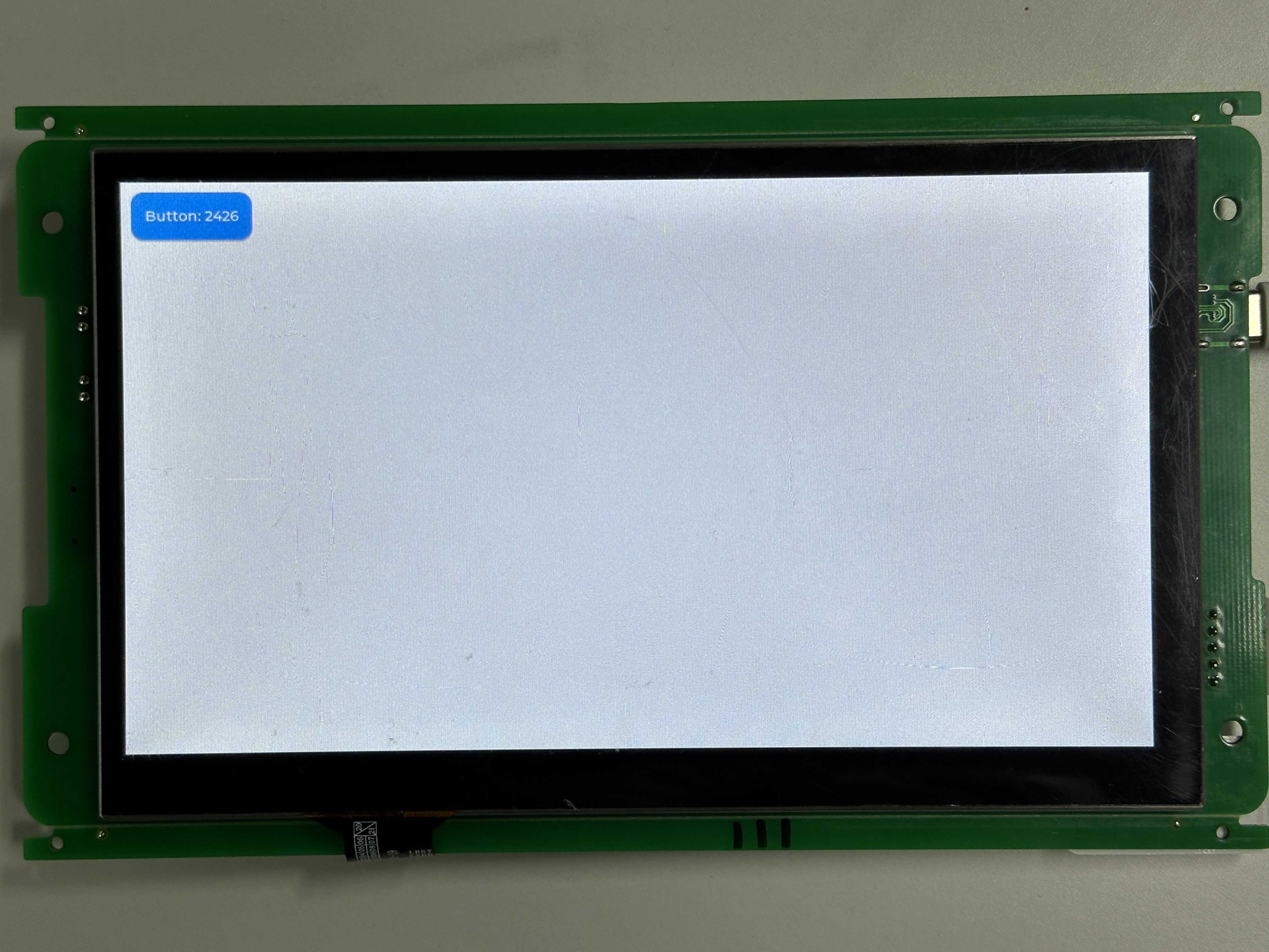
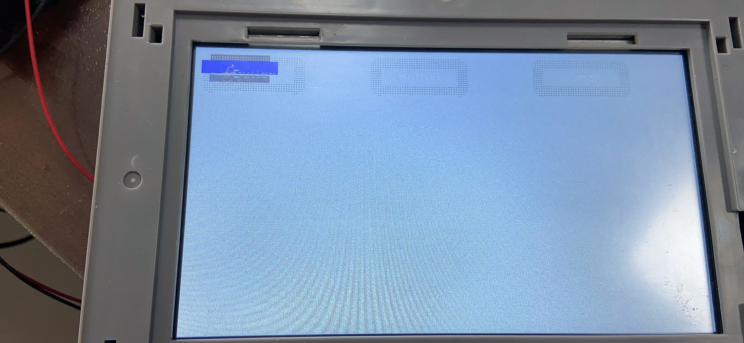

#191 Re: 工业芯 匠芯创 » d122bbv LVGL demo测试 » 2024-05-09 17:22:41
#192 Re: 工业芯 匠芯创 » d133的rtp如何配置? » 2024-05-09 13:38:09
#195 Re: 工业芯 匠芯创 » RISC-V高性能显示控制跨界MCU D13x系列Datasheet » 2024-05-07 08:51:59
#196 Re: 工业芯 匠芯创 » d133打开网口后,编译报错。 » 2024-05-06 11:32:52
#197 工业芯 匠芯创 » d133打开网口后,编译报错。 » 2024-05-06 11:07:46
- Gentlepig
- 回复: 9
报错如下。
bsp\artinchip\hal\syscfg\hal_syscfg.c: In function 'syscfg_gmac_init':
bsp\artinchip\hal\syscfg\hal_syscfg.c:408:42: error: 'SYSCFG_GMAC_RXDLY_SEL_SHIFT' undeclared (first use in this function); did you mean 'SYSCFG_GMAC_TXDLY_SEL_SHIFT'?
  408 |         cfg |= (AIC_DEV_GMAC0_RXDELAY << SYSCFG_GMAC_RXDLY_SEL_SHIFT);
      |                                          ^~~~~~~~~~~~~~~~~~~~~~~~~~~
      |                                            CC bsp\artinchip\sys\d13x\time.c
SYSCFG_GMAC_TXDLY_SEL_SHIFT
bsp\artinchip\hal\syscfg\hal_syscfg.c:408:42: note: each undeclared identifier is reported only once for each function it appears in
  CC bsp\artinchip\sys\d13x\trap_c.c
scons: *** [output\d13x_cbs-nor_rt-thread_can2eth\bsp\artinchip\hal\syscfg\hal_syscfg.o] Error 1
scons: building terminated because of errors.
之前遇到过这个问题,忘了是怎么解决的了,好像是自己加了个这个定义。
今天更新到1.0.4后,再次编译,又遇到这个错误了。
请教,该如何解决?
#198 Re: 工业芯 匠芯创 » 5款Linux桌面环境推荐,你最爱哪个? » 2024-04-29 16:34:54
#199 Re: DIY/综合/Arduino/写字机/3D打印机/智能小车/平衡车/四轴飞行/MQTT/物联网 » 单片机io检测按键输入,电路上如何设计,使可以检测是否接上按键? » 2024-04-27 17:28:06
东莞哇酷科技有限公司开发